113242-3 7
Installation Procedures _____________
Installation should be performed by competent technicians
in accordance with local and state codes. In the absence of
these codes, the installation must conform to applicable
American National Standards: ANSI Z223.1-LATEST EDITION
(National Fuel Gas Code) or ANSI/NFPA NO. 70-LATEST
EDITION (National Electrical Code) or in Canada, the
installation must conform to applicable Canadian Standards:
CAN/CGA-B149.1-M91 (Natural Gas) or CAN/CGA-B149.2-
M91 (Liquid Propane [L.P.] Gas) or LATEST EDITION (for
General Installation and Gas Plumbing) or Canadian
Electrical Codes Parts 1 & 2 CSA C22.1-1990 or LATEST
EDITION (for Electrical Connections).
Unpacking/Setting Up _______________
Remove protective shipping material (i.e., plastic wrap and
optional shipping box) from dryer.
Important
Dryer must be transported and handled in an
upright position at all times.
The dryer can be moved to its final location while still attached
to the skid or with the skid removed. To unskid the dryer,
locate and remove the four (4) bolts securing the base of the
dryer to the wooden skid. Two (2) are at the rear base (remove
the back panel for access), and two (2) are located in the
bottom of the lint chamber. To remove the two (2) bolts located
in the lint chamber area, remove the lint drawer.
With the skid removed, to make it easier to slide the dryer into
its final position, slightly lower all four (4) leveling legs, so
that the dryer will slide on the legs instead of the base frame.
Leveling Dryer
The dryer is equipped with four (4) leveling legs, one (1) at
each corner of the base. Two (2) are located at the rear of the
dryer base, and two (2) are located in the lint chamber (coop).
To increase bearing life and improve efficiency, the dryer
should be tilted slightly to the rear.
Location Requirements ______________
Before installing the dryer, be sure the location conforms to
local codes and ordinances. In the absence of such codes
or ordinances the location must conform with the National
Fuel Gas Code ANSI.Z223.1 LATEST EDITION, or in Canada,
the installation must conform to applicable Canadian
Standards: CAN/CGA-B149.1-M91 (Natural Gas) or
CAN/CGA-B149.2-M91 (Liquid Propane [L.P.] Gas) or LATEST
EDITION (for General Installation and Gas Plumbing).
The dryer must be installed on a sound level floor capable of
supporting its weight. Carpeting must be removed from the
floor area that the dryer is to rest on.
Important
“The dryer must be installed on noncombustible
floors only.”
The dryer must not be installed or stored in an area where it
will be exposed to water and/or weather.
The dryer is for use in noncombustible locations.
!
!
Provisions for adequate air supply must be provided as noted
in this manual (refer to Fresh Air Supply Requirements).
Clearance provisions must be made from combustible
construction as noted in this manual (refer to Dryer
Enclosure Requirements).
Provisions must be made for adequate clearances for
servicing and for operation as noted in this manual (refer to
Dryer Enclosure Requirements).
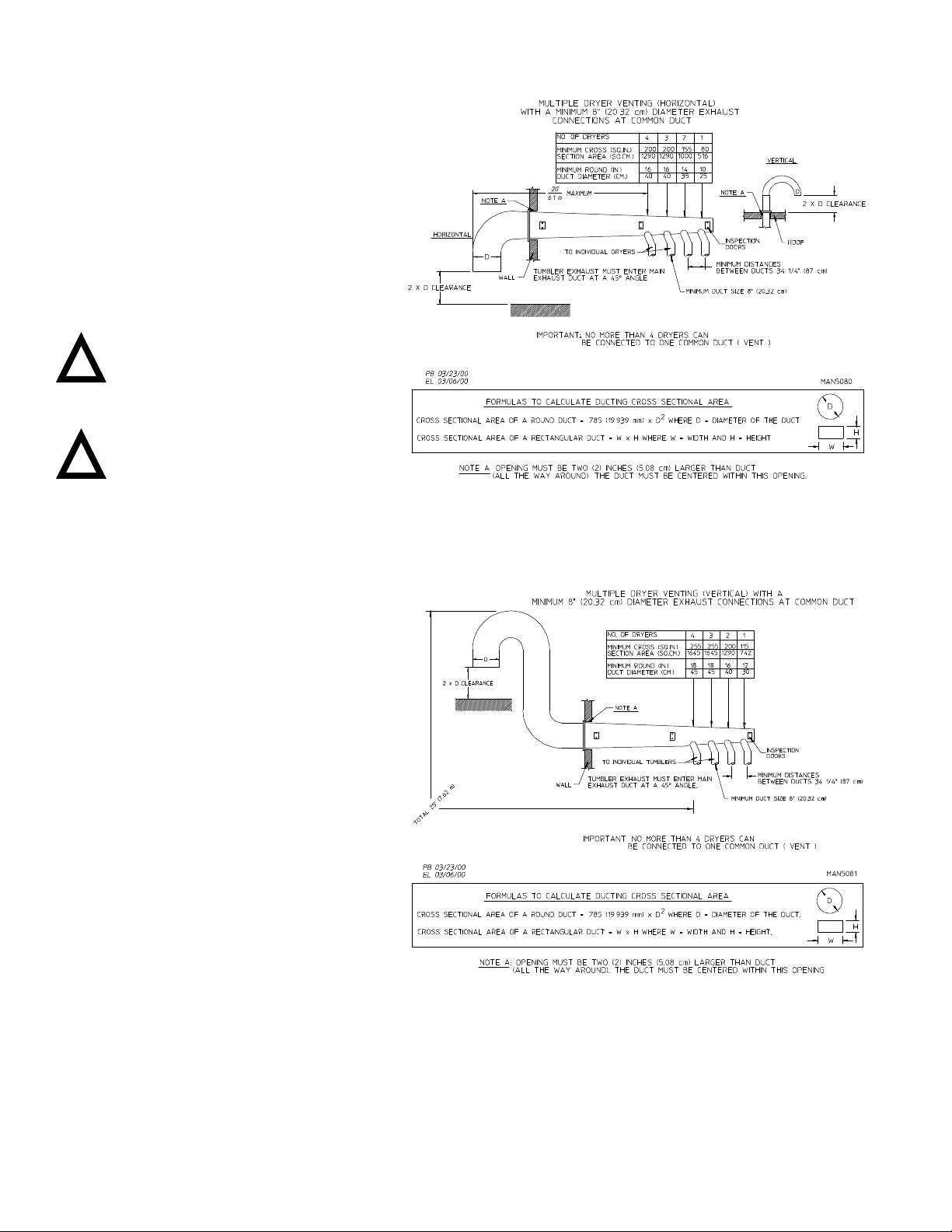
The dryer must be installed with a proper exhaust duct
connection to the outside. as noted in this manual (refer to
Exhaust Requirements).
The dryer must be located in an area where correct exhaust
venting can be achieved as noted in this manual (refer to
Exhaust Requirements).
Important
Dryer should be located where a minimum
amount of exhaust duct will be necessary.
The dryer must be installed with adequate clearance for air
openings into the combustion chamber.
Caution
This dryer produces combustible lint and must
be exhausted to the outdoors. Every 6 months,
inspect the exhaust ducting and remove any lint buildup.
Dryer Enclosure Requirements ______
Bulkheads and partitions should be made of noncombustible
material.
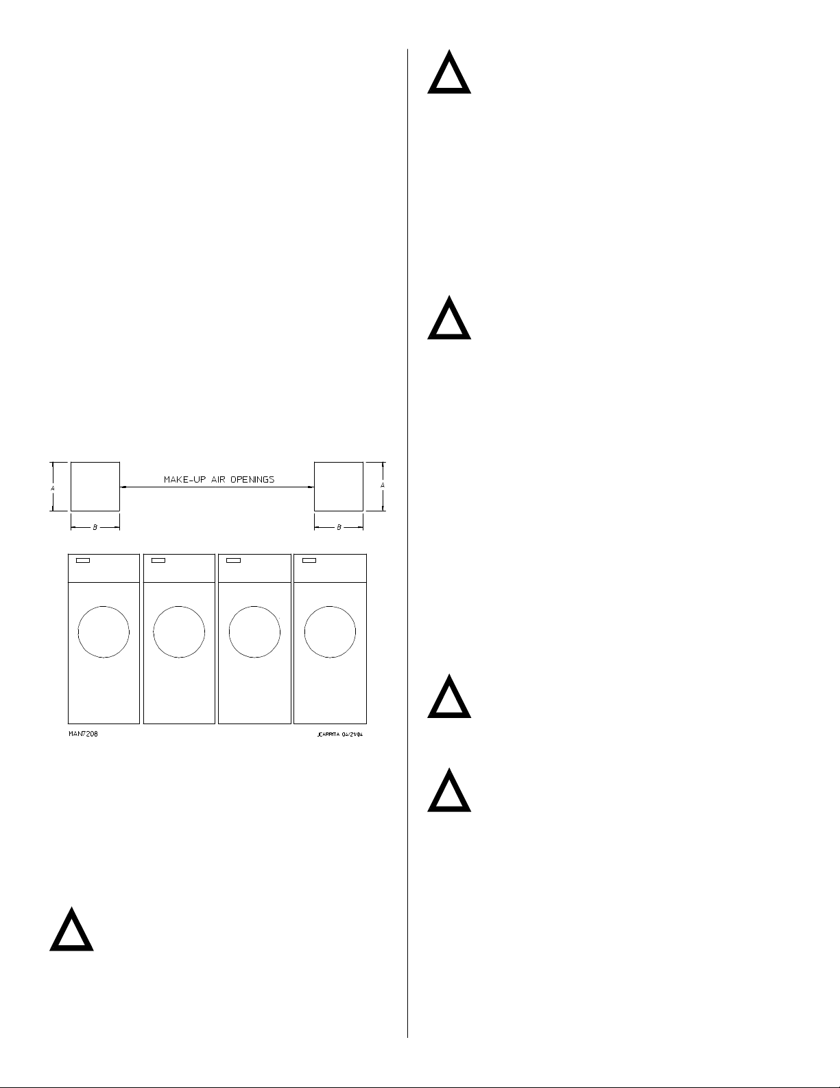
Note
Allowances must be made for opening the control
door
A30-inches (76.2 cm) for optimum opening of load door.
BThe maximum thickness of the bulkhead is 4-inches (10.16 cm).
For electric dryers the maximum thickness of the bulkhead is 1-inch
(2.54 cm) within 3-inches (7.62 cm) from the top of the control door.
CFor gas and electric dryers a minimum overhead clearance of 12-
inches (30.48 cm) is required, providing no sprinkler is located
above the dryer. For steam dryers or if a sprinkler is located above
the dryer, 18-inches (45.72 cm) is required.
DDryer should be positioned 12-inches (30.48 cm) away from the
nearest obstruction and 24-inches (60.96 cm) is recommended for
ease of installation, maintenance, and service.
E2-inch (5.08 cm) minimum is required for opening the control door.
FFlooring should be level or below dryer cabinet for ease of removing
panels during maintenance.
GDryers may be positioned sidewall to sidewall, however a 1/16”
(1.5875 mm) minimum allowance must be made for the opening
and closing of the control door, along with the removal of panels
during maintenance.
!
!
!