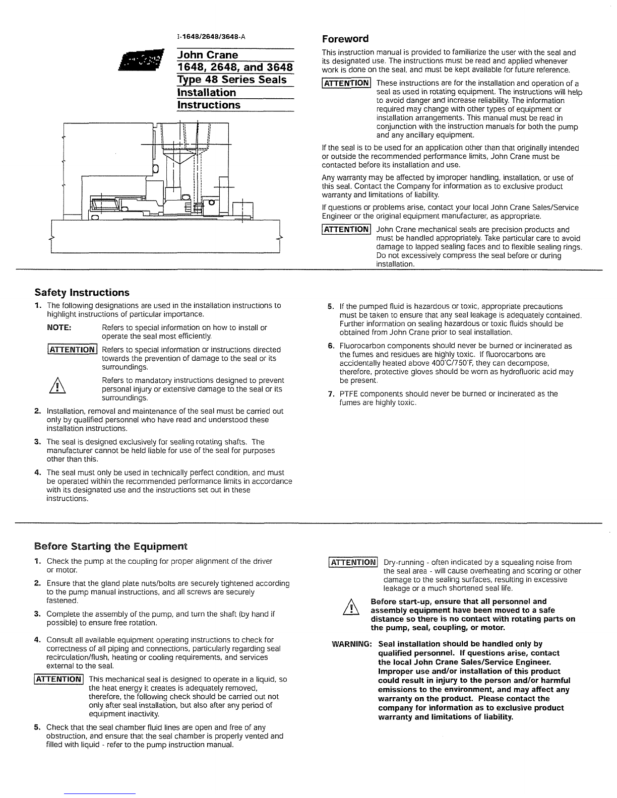
manuals.online logo
Brands
  1. Home
  2. •
  3. Brands
  4. •
  5. John Crane
  6. •
  7. Tools
  8. •
  9. John Crane 48 Series User manual

John Crane 48 Series User manual

John Crane
1648.2648. and 3648
Type48
seiies Seals
Installation
Instructions
Safety Instructions
1.
The following designationsare used inthe installationinstructionsto
highlight instructionsof particularimportance.
MOTE:
Refers to special informationon how to installor
operatethe seal most efficiently.
IATTERITIORI
I
Refersto specialinformationor instructionsdirected
towards the preventionof damageto the seal or its
surroundings.
n
Refers to mandatoryinstructionsdesigned to prevent
personal injury or extensive damage to the seal or its
surroundings.
2.
Installation,removaland maintenanceof the seal must be carried out
only by qualified personnelwho have read and understoodthese
installationinstructions.
3.
The seal is designedexclusively for sealing rotatingshafts. The
manufacturercannot be heldliablefor use of the seal for purposes
other than this.
4.
The seal must only be used intechnically perfect condition, and must
be operatedwithin the recommendedperformancelimits in accordance
with its designateduse and the instructionsset out inthese
instructions.
Before Startingthe Equipment
'1.
Check the pump at the couplingfor properalignment of the driver
or motor.
2.
Ensurethat the gland plate nutslbolts are securely tightened according
to the pump manual instructions,and all screws are securely
fastened.
3.
Completethe assembly of the pump, and turn the shaft (byhand if
possible)to ensurefree rotation.
4.
Consultall available equipmentoperatinginstructionsto check for
correctnessof all piping and connections,particularlyregardingseal
recirculation/flush,heatingor cooling requirements, and services
externalto the seal.
-1
This mechanicalseal is designedto operate in a liquid, so
the heat energy itcreates is adequately removed,
therefore, the following check should becarriedout not
only after seal installation,butalso after any period of
equipmentinactivity.
Foreword
This instruction manualis providedto familiarize the user with the seal and
its designateduse. The instructionsmust be read and appliedwhenever
work is done on the seal, and must be kept availablefor future reference.
1-
These instructionsare for the installationand operationof a
seal as usedinrotating equipment.The instructionswill help
to avoid danger and increasereliability.The information
'
requiredmay change with other types of equipment or
installationarrangements.This manual must be read in
conjunction with the instructionmanualsfor boththe pump
and any ancillary equipment.
Ifthe seal is to be usedfor an applicationother than that originally intended
or outsidethe recommendedperformancelimits, John Crane must be
contacted before its installationand use.
Any warranty may be affected by improperhandling,installation, or useof
this seal. Contact the Company for informationas to exclusive product
warranty and limitationsof liability.
Ifquestionsor problemsarise, contact your localJohn Crane SaleslService
Engineer or the originalequipmentmanufacturer,as appropriate.
-1
John Crane mechanical seals are precisionproducts and
must be handledappropriately.Take particular care to avoid
damage to lappedsealing faces and to flexible sealingrings.
Do not excessively compress the seal before or during
installation.
5.
If the pumped fluid is hazardousor toxic, appropriateprecautions
must be taken to ensurethat any seal leakageis adequately contained.
Furtherinformationon sealing hazardousor toxic fluids should be
obtainedfrom John Crane prior to seal installation.
6.
Fluorocarboncomponentsshould never be burnedor incineratedas
the fumes and residuesare highly toxic. If fluorocarbonsare
accidentallyheated above 400'C1750'F, they can decompose,
therefore, protectivegloves should beworn as hydrofluoricacid may
be present.
7. PTFE components should never be burned or incineratedas the
fumes are highly toxic.
1-1
Dry-running
-
often indicatedby a squealing noisefrom
the seal area
-
will cause overheating and scoringor other
damageto the sealing surfaces, resultingin excessive
leakageor a much shortened seal life.
Before start-up, ensure that all personneland
assemblyequipment have been moved to a safe
distance so there is no contact with rotating parts on
the pump, seal, coupling, or motor.
WARNING: Seal installation should be handled only by
qualified personnel. If questionsarise, contact
the local John Crane SalesfSenrice Engineer.
Improper use andfor installation of this product
could result in injury to the person andlor harmful
emissionsto the environment, and may affect any
warrantv on the oroduct. Please contact the
company for information as to exclusive product
warranty and limitations of liability.
5.
Check that the seal chamber fluid lines are open and free of any
obstruction, and ensurethat the seal chamberis properly ventedand
filled with liquid
-
refer to the pump instructionmanual.
Operating Conditions
The following are non-concurrentoperating limits of the Type 48 Series
Seals. The selectionof materials used inthe construction of the seal
shouldbe madewith regards to their temperature and chemical
resistance/compatibility
with the liquid beingsealed.
Temperature Limits: -40°Cto +260"C/-40°Fto +500°F
dependingon the materialsused
PressureLimits: -1 to 69 bar 91-14.7 to 1000psig
dependingupon size and design
Speed Limits: Up to 25.4 mls/5000 fpm
Typical Type 1648 Seal Arrangement
314'
NPT
OR
I&?-
NPT
\
I
1
,
318'NPT
General Instructions
1.
Be sure to read all instructionscarefully before installingseal.
2.
The John CraneType 1648, 2648, and 3648 Seals are precision
products and are shipped as completelyassembled cartridge seals
for ease of installation.
Part
Name
~ ~
~-
1
MatingRing
8
Snap Ring
15
Cap Screw
2
0-Ring
9
Set Screw
16
Gland Plate
3
Primary Ring
10
Sleeve
17
0-Ring
4
0-Ring
11
0-Ring
18
BushingAssembly
5
Retainer
12
Collar
19
Spring
6
Spring
13
Set Screw
20
Auxiliary Gland
7
Disc
14
Spacer
21
0-Ring(optional)
Type 1648, 2648 and 3648 InstallationDimensions
For dimensionaldata on the seal installation,please refer to the specific
John Crane layout drawing.
Im~erialtMetricConversions:
0.005"
=
125 micrometer
0.0005" per
inch bore
=
15 micrometerl3cm
0.001
"
=
25 micrometer
installingthe
Seal
1.
Beforestarting the installation,readthroughthe following instructions
carefully,as the sequence may be differentdepending on the
construction of the pump.
2.
Remove the seal from it's packaging,inspectthe seal for any damage
and wipe clean.
3.
The equipment should be cleanand meet the specifications noted in
"Preparing the Equipment". Check the sleeve and gland secondary
seal. Apply a lubricant, if necessary, to assist inassembly. Dow
Corning#4 or equivalent should be used. The gland plate nuts should
be lubricated in order to achieve proper torque values.
4.
The seal cartridge containseither two (2)or four (4)spacers that set the
working heightof the seal. On some equipment.the lowerspacer is not
accessibleonce the seal is installedonto the shaft. Inthese instances
removethe lower spacer.
5.
(For Overhung Pumpswith Single Row Collar) Check that the drive
collar set screwsare engaged inthe sleeve holeswithout touching the
shaft. Slidethe seal cartridgeonto the shaft as close to the nearest
obstruction as possible. Positionthe gland plate so the flush
connection, marked"F" is at or near top deadcenter, Installthe seal
Preparing the Equipment
1.
Check the shaft and seal chamber dimensions andfinishes as noted
Check dimensions per specificJohn Crane Layoutdrawing.
2.
Measurethe shaft end floatlend play. The maximum value shouldnot
exceed 0.005" F.I.M.. Remove all sharp edges and bunsover which the
seal sleeve must pass.
NOTE: It
is
recommendedthat the pumpand it's installationmeetthe requirer
chamber onto the pump and tightenthe bolts to the bearingframe.
Slidethe seal cartridgeonto the studs. Handtighten the gland plate nuts.
5.
(For Between Bearing Pumpswith Single Row Collar) Check that
the drive collar set screws are engagedinthe sleeve holeswithout
touching the shaft. Slide the seal cartridge onto the shaft. Positionthe
gland plateso the flush connection,marked
"F"
is at or near top
dead center. Hand tightenthe gland plate nuts.
5.
(For Between Bearing Pumpswith Double Row Collar) Check that
the drive collar set screws are engagedinthe sleeve but do not protrude
throughthe outer row threaded holes of the collar so as to touch the
shaft during assembly. Slide the seal cartridge onto the shaft. Position
the gland plate so the flush connection,marked"F" is at or near top
dead center. Installthe seal cartridgeonto the studs. Handtighten the
gland platenuts.
6.
Reassemblethe pumpand make all necessary impeller adjustments.
7.
Tightenthe gland platenuts inan alternatingpattern until secure
(114 turns, 180'apart),with gland plate and face of pump seal chamber
metal-to-metal.
Typical Type 2648 Seal Arrangement Typical Type 3648 Seal Arrangement
Part
Name
1
Mating Rinq
7
Disc
13
0-Ring
19
Sleeve
25
Spacer
2
0-Rinq
8
Snap Ring
14
Retainer
20
0-Ring
26
Cap Screw
3
Primary Ring
9
Set Screw
15
Spring
21
Gland Plate
27
Collar
4
0-Ring
10
Mating Ring
16
Disc
22
0-Rinq
28
Set Screw
5
Retainer
11
0-Ring
17
Snap Ring
23
Gland Plate
29
Cap Screw
6
Spring
12
Primary Ring
18
Set Screw
24
0-Ring
30
Pumping Ring
3.
Check the squareness or face runout of the seal chamber face to the
shaft. The maximum value should notexceed
0.0005"
per inchof seal
chamber bore
ill?:,
Sai;?
5r
Hib3
-3
Idit
4.
Measure the concentricity of the seal chamber bore to the shaft.
This value should not exceed
0.005"
F.I.M.
5.
Measure the shaft runout at the seal location. The maximum value
should not exceed
0.001"
F.I.M.
NOTE:
If the measured dimensions exceed these values given, correct
the equipment to meet the specifications prior to installing the
seal cartridge.
ents of the latest edition of API Standard
610.
Equipmentthat meets these requirements will aid in extending MeanTime Between Planned Maintenance.
8.
Check the glandlpump housing gap at each stud location to ensure
even tightening. Tighten the outside lockcollar set screws.
9.The collar can be rotated with the spacers intact. Once all the collar set
screws are tightened loosen the cap screws and rotatethe spacer free
of rotating parts. The spacer can be locked into place, out of the way of
the collar, for future use, or removed and stored. Repeatthe above for
each spacer independently.
10.
Use the spacers any time the gland nuts or collar set screws are
loosenedto properly set the seal to it's working height.
11.
Piping connections can now be made to the gland plate.
WARMING:
Be sure to make the proper gland plate connections
tothe process and atmospheric sides of the seal.
After
the Equipment
has
Run
'1.
Ensure that the pumpis electrically isolated.
Ifthe equipment has been used ontoxic or hazardous fluids,
ensure that the equipment is correctly decontaminated and
made safe prior to commencing work. Remember fluid is
oftentrapped during draining and may exist outside the seal
The pumpinstruction manual should be consulted to check
for any special precautions.
2.
Ensure that the pump is isolated bythe appropriate valves.
Check that the fluid is drained and pressure is fully released.
The spacers must bepositioned out of the way of the
collar and tightened down prior to starting upthe pump
Removing the Seal Cartridge
1.
Referringto the pump installationmanual, dismantlethe equipment
sufficientlyto expose the gland plateand seal chamber.
2.
(For Overhung Pumps with Single Row Collar)
Reinstallor rotate
the spacer back into placeover the collar and retightenthe cap
screws. Loosenthe set screws inthe collar. The set screws that
engagethe spacer need only be flushwith the top of the spacer. The
remaining set screws should be loosenedjust enoughso they still
engagethe sleeve drill through holes. Evenly slacken and remove the
gland plate nuts and carefully slidethe plate off the studs. Removethe
pump casinglsealchamber and the abutmentor spacer when fitted,
and then completethe removal of the seal cartridge in the reverse
order of installation.
2.
(For Between Bearing Pumps with Single Row Collar)
Reinstall
or rotatethe spacer back into placeover the collar and retightenthe
cap screws. Loosenthe set screws inthe collar. The set screws that
engage the spacer need only beflushwith the top of the spacer. The
remaining set screws shouldbe loosenedjust enoughso they still
engagethe sleeve drill through holes. Evenly slackenandremovethe
gland plate nuts and carefully slidethe seal cartridge off the shaft.
2.
(For Between Bearing Pumps with Double Row Collar)
Loosen
the collar set screws and removethe collar. Remove the raised
material onthe shaft in the area of the set screws and replacethe
collar. Tightenthe inner set screws onto the sleeve. Reinstallor rotate
the spacer back into placeover the collar and retightenthe cap
screws. Loosenor installthe collar set screws that correspondto the
spacer to beflush with the top of the spacers. Evenlyslacken and
removethe gland plate nuts and carefully slidethe seal cartridge
off the shaft.
The spacers needto be in place prior to seal assembly
removal. Failureto installthe spacers canresult in damage
to the seal faces.
Storage and Transport
1.
Mechanicalseal assembliesand component parts must be treated
with extreme care to protect them from damage due to handlingand
deterioration. Inall cases if establishedcompany proceduresdiffer
from the instructions providedinthis document, the established
proceduresshall be followed.
2.
Warehouse Shelf Storage
a) John Crane mechanical seals and components are packagedto
protect themfrom airbornedirt and grit, as well as from
mishandling. If the packagingis removed for inspection, it should
bereplaced. Seals are generally packageddry. Elastomershelf life
can be a factor if the storage periodis in excess of
2
years.
b) Ifstorage is inexcess of
1
year, it is recommendedthat the primary
and matingrings be inspectedfor flatness prior to installingthe
seals into the pump.
3.
Storage of SingleSeals inPumps
a) If the mechanical seal is to be stored in the equipment,the seal
cavity shall bedrained of allwater to prevent damage due to
freezing temperature.
b) Any foreign mattershould beremovedas soon as possible after
delivery of the pump on site. The openarea betweenthe gland
plate and sleeve must bemaskedto excludedirt after cleaning.
c) Cover pump suction and discharge flanges to exclude
airbornedebris.
d)All open ports inthe glandplate and seal chamber must be
pluggedwith metal plugs.
e) Seals that will be used on hydrocarbonbasedservicescan be
fogged and filled approximately one-quarter(114) with aVPI oil.
Alternately the seals can be preservedusing an oil, or other
suitable liquid, mist system.
f)
Mark and rotatethe shaft several revolutions weekly. Leavethe
shaft 90' from the previous position.
g) Seals in storage for morethan
2
years shouldbe disassembled
to allow inspection of the primary and matingringfaces.
Quality Assurance Maintenance
This seal has beenassembled inaccordancewith John Crane Quality No maintenanceof a seal is possiblewhile installed.Therefore, it is
Assurance Standards and with proper maintenanceand use will give safe recommendedthat a spare seal unit and matingring be held in stock to
and reliable operationto the maximum recommendedperformanceas allow immediatereplacementof aremovedseal.
shown inany relevant approvedJohn Crane publication. It is recommendedthat used seals are returnedto aJohn Crane Seal
RebuildingCenter, as rebuildingto as-newspecificationsmust be carried
out by qualifiedpersonnel.
John Crane International
EngineeredSealingSystems
It is the responsibilityof the equipmentuser to ensure that any
parts beingsent to a third party have appropriate safe
handlinginstructions externallyattachedto the package.
North
America LatinAmerica Europe, Asia, Africa Asia Pacific
MortonGrove, lll~no~s
USA
Mex~coC~ty,Mex~co Slough,
UK
Singapore
Tel: 847-967-2400 Tel: 52-5-567-451
1
Tel: 44-1753-224000 Tel: 65-222-9161
Fax: 847-967-3915 Fax: 52-5-587-2342 Fax: 44-1753-224224 Fax: 65-223-5035
1
-800-SEALING
If
the
products
featured
will
be
used
in
a
potentially
dangerous
and/or
hazardous
process,
your
John
Crane
representative
should
be
consulted
priorto
their
selection
and
use.
In
the
interest
of
continuous
development.
John
Crane
Companies
reserve
the
right
to
alter
designs
and
specifications
v/~thou;
prior
notice.
01996
John Crane
International
Pnnt
6/96
IS0
9001
Certified

This manual suits for next models

3

Popular Tools manuals by other brands

Draper STORMFORCE MT400 instructions

Draper

Draper STORMFORCE MT400 instructions

Omer PL 110 SJ Use, maintenance and spare parts manual

Omer

Omer PL 110 SJ Use, maintenance and spare parts manual

Senco SCN200 operating instructions

Senco

Senco SCN200 operating instructions

Hozelock 2597 manual

Hozelock

Hozelock 2597 manual

Trumpf TruTool F 140 (2A1) manual

Trumpf

Trumpf TruTool F 140 (2A1) manual

CP 4123 Safety & Operating Instructions

CP

CP 4123 Safety & Operating Instructions

ReelCraft 30000 Series Operating instructions and parts list

ReelCraft

ReelCraft 30000 Series Operating instructions and parts list

PFS GB267 instruction manual

PFS

PFS GB267 instruction manual

Neilsen CT4342 Original instructions

Neilsen

Neilsen CT4342 Original instructions

RAWLINK 80023 instruction manual

RAWLINK

RAWLINK 80023 instruction manual

Freud RTP1000 Set up and instructions

Freud

Freud RTP1000 Set up and instructions

Fumex ASE 130 manual

Fumex

Fumex ASE 130 manual

AGI GRAINMAXX 7400 Series Operator's manual

AGI

AGI GRAINMAXX 7400 Series Operator's manual

Ingersoll-Rand 132 Maintenance information

Ingersoll-Rand

Ingersoll-Rand 132 Maintenance information

KIPP KIPPflexX K1555 operating instructions

KIPP

KIPP KIPPflexX K1555 operating instructions

Ross RA502 instructions

Ross

Ross RA502 instructions

Okoia NT1 quick start guide

Okoia

Okoia NT1 quick start guide

Bostitch IC50-2-E Original instructions

Bostitch

Bostitch IC50-2-E Original instructions

manuals.online logo
manuals.online logoBrands
  • About & Mission
  • Contact us
  • Privacy Policy
  • Terms and Conditions

Copyright 2025 Manuals.Online. All Rights Reserved.