John Downey Steamin Demon Classic User manual

Steamin Demon®
Classic
High-Flow Carpet Cleaning System
Operating Manual
For Assistance Call Toll-Free
1-888-413-6748
®

-1-
Table of Contents
Section One Page #
I. Pre Extraction
A. Cleaning Machine . . . . . . . . . . . . . . . 3
B. Chemicals . . . . . . . . . . . . . . . . . . . 3
C. Sink Fittings . . . . . . . . . . . . . . . . . . 3
D. Unrolling Hoses . . . . . . . . . . . . . . . . 3
E. Hooking up to the Machine . . . . . . . . . . 3
F. Prespraying and Spotting Carpets . . . . . . . 4
II. Extraction procedure
A. Before you Begin . . . . . . . . . . . . . . . . 4
B. Cleaning Carpet . . . . . . . . . . . . . . . . 5
C. Hose Techniques . . . . . . . . . . . . . . . . 6
D. Unhooking and Cleaning the Machine . . . . . 6
III. Hoses
A. Attaching Extra Hoses . . . . . . . . . . . . . 8
B. Hose Reels . . . . . . . . . . . . . . . . . . . 8
IV. Hand Tool Attachments . . . . . . . . . . . . . . 8
Section Two: Warranty . . . . . . . . . . . . . . . . 9
Section Three: Trouble-Shooting . . . . . . . . . . . . 10

-2-
Section One
I. Pre extraction
A. Cleaning the Machine- To ensure
the proper performance of this machine
certain critical areas must be cleaned
daily. These areas being the water filter,
float switch, air filter and the vacuum
shoe (fig. 2, fig. 3, fig. 4 and fig. 5). If
these areas are not cleaned on a regular
basis you may as well throw the machine
away as it will not perform properly. In-
structions on how to clean these areas
can be found on pages 6 and 7.
B. Chemicals
1. Fill the defoamer bottle, attached to
the machine, about 3/4 full with Steamin
Demon Bubble Blaster Defoamer (fig.6).
2. Fill the Dial a Mixer Sprayer with
Demon Clean Carpet Prespay (fig. 7).
C. Sink Fittings- Each machine comes
with five sink fittings, an extra pump
impeller, a lip hook, a caddie, a spotter,
a quart of prespray, a quart of defoamer,
a 33 foot prespray hose with a Dial-a-
Mix sprayer (fig. 8). The sink fittings
convert the aerator threads on the fau-
cet to garden hose threads.
1. To install sink fittings, use your
hand or a or a pair of pliers to remove
the aerator from the faucet. Avoid
using plastic faucets or spickets. Then
install the corresponding sink fitting
on the faucet (fig. 9).
2. The Standard Sink Fitting (fig. 10)
has both inner and outer threads. It will
fit about ninety percent of all faucets.
3. The Standard Extended Sink Fitting
(fig. 8) has the same male thread as the
Standard Sink Fitting. These threads,
however, are extended above the fitting.
This fitting is used on recessed faucets
commonly found in bathrooms.
Figure 2: Water filters
Water filters
Water filter
swivel nut
Figure 3: Air filter
Air filter
Figure 4: Float switch
Float Switch
Figure 5: Vacuum shoe
Vacuum
Shoe
Side vacuum slots

-3-
4. The 13/16 Male Fitting is the third
most common fitting.
5. The 13/16 Female and 3/4 Female
Sink Fittings are rarely used; but will
fit into some old gooseneck faucets.
6. Permanent Sink Fitting- These are of-
fered as an accessory. They are nice for
facilities that do not want to mess with
installing and removing sink fittings.
They permanently install on the faucets,
and all you need to do to connect to the
faucet is to remove the aerator.
7. For garden hose-type spigots, sink
fittings aren't necessary. The garden
hose swivel nut on the end of the red
pressure hose connects directly to gar-
den hose spigots.
8. If connecting to a water heater, open
water heater valve to drain any debris out
of the bottom of the water heater before
connecting your red pressure hose to it.
D. Unrolling Hoses- Place one arm
through the middle opening of the hoses
(fig. 11) and feed the hose out as you walk
away from the machine toward the sink.
Hint: New hoses take about a week to
break in. If you roll and unroll the hoses
the same way every time they will break
in quicker and be easier to work with.
E. Hooking the Machine to the Sink
1. Tighten the garden hose swivel nut
(fig. 12) to the sink fitting. Turn hot wa-
ter valve all the way open and open the
pressure valve (fig. 12).
2. Open drain valve and place in sink,
toilet, or other drain (fig. 13).
3. Plug electric cord into a grounded
three pin outlet.
Important: The most common mistake
made with this machine is forgetting to
open all the valves. Remember that there
are valves at both ends of each hose
(pressure and drain). If any of the valves
Figure 6: Filling defoamer bottle
Figure 7: Filling prespray bottle
Bubble Buster Defoamer
Demon Clean Prespray
Demon Clean
Prespray
Bubble Buster
Defoamer
Dial-a-Mix
Presprayer
Prespray
Hose
Lip Hook
1-1/16" Socket
Ear Washer
Pump Impellor
Caddie
Spotter (not shown)
13/16 Female
3/4 Female
13/16 Male
Standard
Extended
Standard
Figure 8: Contents of caddie
Aerator
Sink Fitting
Figure 9: Attaching sink fitting to faucet

-4-
are closed, the machine will not work .
F. Prespraying and spotting carpet
1. First unroll the prespray hose. Then
snap the hose quick connect into the
prespray plug (fig. 14).
2. When prespraying carpet, concentrate
prespray on the main traffic areas and
spots. Prespray spots heavily and work
in the chemical by rubbing the spot with
your foot. Rinse the spot thoroughly
(three to four passes) and make a final
dry pass. Once done prespraying, discon-
nect prespray hose from the machine, re-
lease the pressure from the hose with the
dial-a-mix sprayer, and place them in the
caddie (fig. 17). On heavily soiled carpet
it may be necessary to use a carpet rake to
agitate the dirtiest areas of the carpet.
3. With stubborn stains you may need
to boost your detergent. You can do this
with your spotter. Simply spray the stain
with your spotter, work in with your foot
and rinse thoroughly (three to four passes
followed by a final slow dry pass).
II. Extraction Procedures
A. Before You Begin- Before starting
your machine , familiarize yourself with
the control panel (fig 16). This panel
has four switches and an indicator light.
1. Vacuum switch: This toggle switch
turns your vacuum motor on and off. It
should remain ON during the entire ex-
traction process.
2. Defoamer Momentary Toggle
Switch: This switch will be used on
an “as needed” basis during the extrac-
tion process.
3. Jet Spray Switches: For your conve-
nience, there are two jet spray switches.
One is a toggle switch and the other is
a push button switch. Use the switch
Inner Threads
Outer Threads
Figure 10: Inner and outer threads
of Standard Fitting
Washer
Figure 11: Unrolling hoses
Garden Hose
Swivel Nut
Drain Valve
(open)
Sink Fitting
Pressure Valve
(open)
Figure 12: Hoses hooked to sink
Figure 13: Hose valves (open and closed)
Pressure
Valve
(open)
Drain
Valve
(closed)
Drain
Valve
(open)
Pressure
Valve
(closed)

-5-
that is most comfortable for you. The
indicator light will light up whenever
either of these switches are activated.
These switches control the water flow
to the carpet.
B. Cleaning Carpet
1. Turn vacuum switch on.
2. Position your machine for a cleaning
pass (fig. 18). Keep both your hands on
the machines handle.
3. How to make a cleaning pass. Turn on
one of the jets spray switches and walk
the machine backward. Work the hoses
with your feet. Apply enough upward lift
on the handle to keep the nose of the ma-
chine firmly on the carpet (fig.18).
4. At the end of your cleaning pass, turn
jet spray switch OFF and continue walk-
ing the machine backwards a few inches.
This will allow the machine to pick up
any excess moisture.
5. Reposition the machine for the next
pass (overlap approximately two to three
inches) and repeat steps three and four.
6. During your cleaning pass, if you
notice a lot of soap residue in the view
window, pull the defoamer switch up for
a second or more. If you ever hear the
RPM’s of your vacuum motor decrease,
pull the defoamer switch up. This al-
lows defoamer to be drawn into the re-
covery tank and kill the soap suds.
IMPORTANT: Many carpets have tre-
mendous amounts of soap residue in
them. This machine is very efficient at
removing these residues. To protect your
vacuum motor from the soap suds that
can build up in your recovery tank, peri-
odically pull the defoamer switch up.
IMPORTANT: When using extra
hoses, hose reels, or really hot water,
your discharge pump may run hot and
Figure 14: Snapping in prespray hose
Figure 15: Prespraying carpet
Figure 16: Control panel
Jet spray switches Vacuum switch
Defoamer
switch
Indicator light
Tube
connector
Figure 17: Caddie with chemical
and prespray hose
Dial-a-mix
sprayer
Prespray
plug
Hose quick
disconnect
Prespray
hose

-6-
automatically shut off. A protective ther-
mal switch within the pump is respon-
sible for this. If this should occur, sim-
ply remove the thumb knobs (fig. 19) and
push the top of the engine compartment
cover back a couple of inches. This al-
lows the heat inside the engine compart-
ment to vent, thus decreasing the tem-
perature of the discharge pump.
IMPORTANT: For flood restoration
or work that requires more then 200
feet of hose, and optional dual dis-
charge pump is available. This inter-
nally mounted discharge pump will
increase your pump's flow capability
about 50 to 80 percent. Do not oper-
ate the Steamin Demon in standing
water, ELECTRICAL SHOCK MAY
OCCUR.
C. Hose Techniques- The hoses on your
machine provide it with a high volume
of water supply and discharge capabili-
ties. They can also get in your way. Here
are some tried-and-true techniques that
will be helpful to you.
1. Always try to work away from your
hoses.
2. The hose strap (fig. 20) on the handle
allows you to switch the hoses from one
side of the machine to the other.
3. During extraction, keep both your
hands on the handle and work the hose
with your feet (fig. 18).
D. Unhooking & Cleaning the Machine
1. Tilt the machine to the RIGHT (fig.
21) to manually activate the discharge
pump. This will drain the recovery tank.
2. Unplug the electric cord.
3. Clean the Water Filter. To clean the
water filter remove the water filter by
unscrewing the garden hose swivel nut
Figure 18: Cleaning pass
Both hands on
handle.
Lift upward
slightly on
handle to create
downward force
on vacuum
shoe.
Work hoses
with your feet.
Figure 19: Hot pump
Move engine
compartment
cover back
to cool
pump
motor
faster.
Pump
Figure 20: Moving hose hanger from
one side of handle to the other.
Thumb knobs

-7-
and removing the water filters from
the recovery tank (fig. 22), lift up the
lint filter (fig 23), and rinse off both
the lint and primary filter.
4. Cleaning the air filter. To clean
the air filter use your hands to wipe
off any debris. Once or twice a month
the air filter should be removed and
cleaned (fig. 24). To do this remove
the wing nut, nylon washer and middle
brace. Then clean thoroughly and re-
place. Do not operate this machine
without a clean air filter. To do so will
dramatically reduce the life and per-
formance of the vacuum motor.
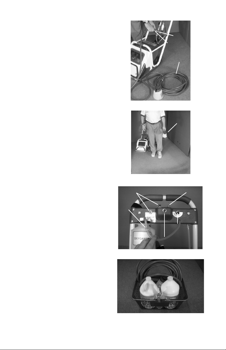
5. Clean the float switch. First, un-
screw the brass knurl nut (fig.22) and
lift the float switch up. Then spray
out any debris that has built up inside
the float switch with your Dial-a-Mix
sprayer (fig. 25).
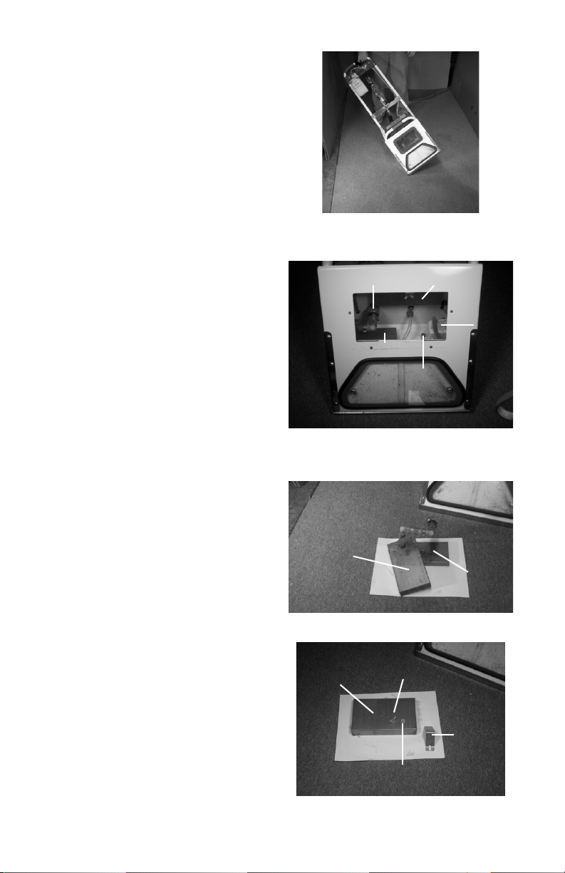
6. If it is needed, remove the drain plug
(fig. 26) from the bottom of the recovery
tank and spray out the bottom of the re-
covery tank with the Dial-a-Mix sprayer.
7. If needed remove and clean the
water channel. To do this remove the
two thumb nuts from the underside of
the machine (fig. 29). Lift out the
water channel (fig. 25) and clean.
8. Clean the vacuum shoe and the side
vacuum slots with the lip hook provided
with each machine (fig. 26 and 27).
9. Replace the air filter, float switch,
drain plug, water channel and water
filter. Make sure the water filter sits
flat on the bottom of the recovery tank
and that its garden hose swivel nut is
tightened securely.
10. Clean the exterior of the machine
with a damp cloth and windex.
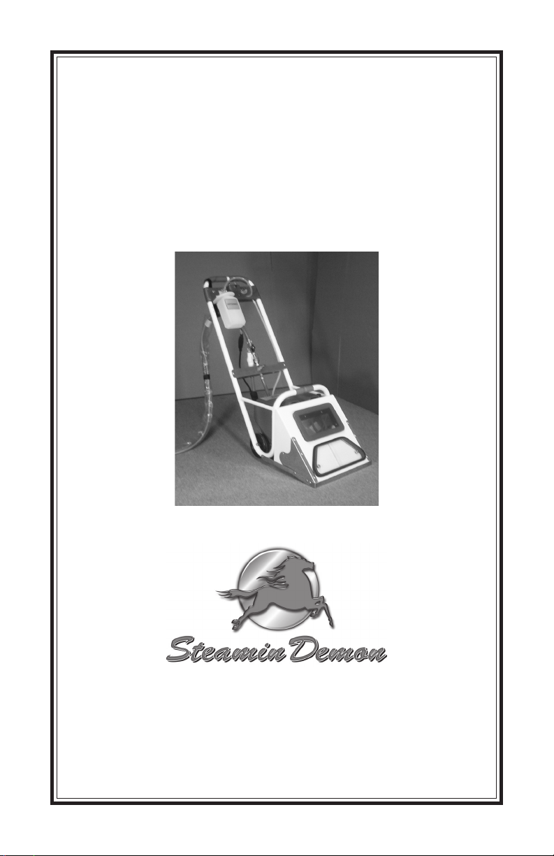
11. Unscrew the pressure hose (the
red hose) from the sink fitting. Open
then close the pressure valve to release
the water pressure.
Figure 21: Tilt machine to right to
manually activate discharge pump
Figure 22: Recovery tank components
that must be cleaned
Water filter swivel nut Air filter
Water filters
Float
switch
Thumb nut
Figure 23: Water filter assembly
Lint filter
Primary
Filter
Figure 24: Air filter assembly
Air Filter Nylon wing nut
Nylon washer
Middle
brace

-8-
12. Close the drain valve (on the clear
hose).
13. Remove the sink fitting from the
faucet and replace the aerator.
14. Roll the hoses (fig. 29). Always
roll the hoses in the same direction, ei-
ther clockwise or counter clockwise. If
you do they will break in nicely for you.
15. If you store the machine make sure
that it is in a place that will not freeze.
Freezing this machine will damage it.
III. Hoses
A. Attaching Extra Hoses- Extra hoses
are sold in 50 foot sections (fig.30) with
valves on all the ends. To attach just
align the pressure and drain hoses and
tighten the corresponding garden hose
fittings. Make sure all valves are open
before operating.
B. Hose Reels- Hose reels may be
purchased with the machine (fig 31).
They come in pairs one hose reel for
the pressure and one hose reel for the
drain hose. These hose reels can hold
100 feet, 150 feet, 200 feet, and 250
feet of hose depending on your needs.
IV. Hand Tool Attachments
These attachments may be purchased
with your machine. It consists of 25
feet of vacuum and pressure hoses.
Separate heads are available for stair
and furniture cleaning. A wand attach-
ment is also available. To connect the
hand tool attachment to the machine:
A. Remove the window channel (fig.
29).
B. Push down on the hand tool win-
dow channel to seal its front gasket
and turn vacuum switch on.
C. Snap the red pressure hose into the
plug on the front of the machine.
Figure 25: Cleaning float switch
(unplug machine before doing this)
Water
channel
Water channel gasket
Figure 26: Remove brass thumb nuts to
remove water channel for cleaning
Brass thumb nuts
Figure 27: Cleaning vacuum
shoe with lip hook
Figure 28: Rolling up hoses
Always roll
hoses in the
same direction.
These are being
rolled up
clockwise.
Drain plug
Side vacuum slots

-9-
Figure 32: Hand Tool Attachment
Hand Tool Channel
Window Channel
SECTION TWO: WARRANTY
Steamin Demon Inc. conditionally warrants all major structural parts (recovery tank,
filters, axle, handle, internal braces, stainless steel lips) and all nonstructural, plastic
and electrical parts for a period of one year from date of purchase. In addition, if
Demon Clean Prespray and Bubble Buster Defoamer are the only chemicals used in
the dial-a-mix sprayer and defoamer injection systems, those systems will be war-
ranted for the life of the machine. This warranty includes the cost of shipping war-
ranty-replacement parts or machines to the distributor or end-user, but does not in-
clude the cost of shipping parts or machines to the factory for inspection or repair. The
warranty is subject to the conditions listed below:
•This warranty is made only to the original purchaser and will only be honored
when the machine is used in accordance with the directions and instructions
described in the Operation and Maintenance Procedure Manual.
•This warranty does not include any product showing signs of abuse, misuse,
improper voltage, shipping damage, lack of proper maintenance, alterations,
use of nonapproved chemicals (call us), gaskets, finishes, polycarbonate, fire,
flood, normal wear or other causes beyond Steamin Demon Inc.’s control.
Figure 29: Hoses secured with bungee cords
Figure 30: 50 ft. section of extra hose
Figure 31: Hose reels
Caddie
Pressure
hose reel
Drain
hose reel

SECTION THREE: TROUBLE-SHOOTING
Solution
1. Open all drain valves (fig. 13).
2. Clean float switch (fig. 25).
3. Remove thumb knobs & push
engine compartment cover
back a few inches (fig. 19).
4. Unkink hose.
5. Tighten water filter swivel
nut (fig. 2) or replace impeller.
6. Clean filters (fig. 23).
7. Replace.
1. Turn water on.
2. Open all valves (fig. 13).
3. Unkink hose.
4. Replace.
5. Replace.
1. See above section: “Recov-
ery tank will not drain.”
2. Increase defoamer injection
(see page 5).
1. Plug in.
2. Reset circuit breaker.
3. Call us.
1. Reseat quick connect.
1. Quit using them.
1. Clean air filter (fig. 24).
2. Clean vacuum shoe (fig. 27)
and side vacuum slots (fig. 26).
3. Replace water channel
(fig. 25).
1. Immediately stop operating
and call us.
1. Separate tube connector
above defoamer bottle. Open
defoamer switch and blow
through tube until unclogged
(fig. 16).
Turn on.
Sit vacuum shoe on carpet.
Problem
Recovery tank
will not drain
No water supply
RPM’s of vacuum motor
going dramatically down
Vacuum motor will not
turn on
Water going to machine
but not to prespray system
Hazing of view windows
Slow drying times or carpet
streaking
Machine shocks you
Defoamer not injecting
Cause
1. Closed drain valve(s)
2. Dirty float switch
3. Hot pump
4. Kinked drain hose
5. Pump not priming
6. Clogged water filters
7. Bad pump or float switch
1. Water not turned on
2. Closed valve(s)
3. Kinked hose
4. Broken or frozen solenoid
5. Broken jet spray switch or
indicator light
1. Recovery tank full of water
2. Excess soap residue in carpet
1. Check wall plug and plug on
back of machine
2. Check building's circuit
breaker
3. Bad switch, loose wire or bad
motor
1. Quick connect not seated
properly
1. Use of strong solvents
1. Obstructed air filter
2. Obstructed vacuum shoe
3. Worn gaskets (you should
hear sucking noises on water
channel)
1. Short or improper ground in
either machine or outlet.
1. Clogged defoamer valve.
2. Vacuum motor not on.
3. Vacuum shoe not sitting on
carpet.
-10-
Table of contents