manuals.online logo
Brands
  1. Home
  2. •
  3. Brands
  4. •
  5. JohnDow Industries
  6. •
  7. Jack
  8. •
  9. JohnDow Industries JDI-LP5 User manual

JohnDow Industries JDI-LP5 User manual

Other JohnDow Industries Jack manuals

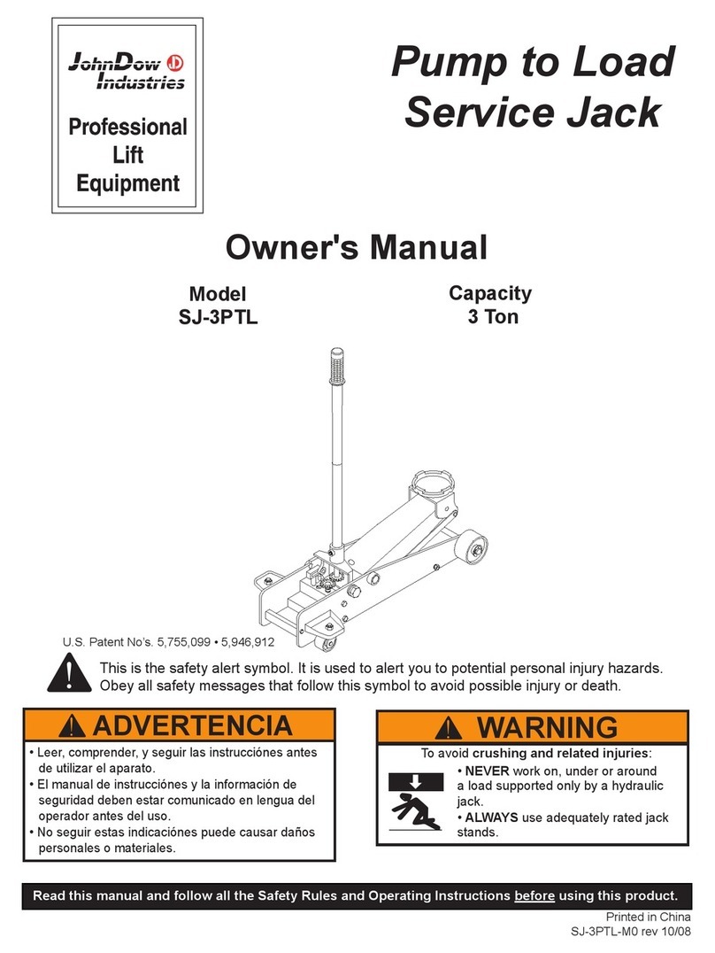
JohnDow Industries SJ-3PTL User manual

JohnDow Industries

JohnDow Industries SJ-3PTL User manual

Popular Jack manuals by other brands

Pittsburgh 62590 Owner's manual & safety instructions

Pittsburgh

Pittsburgh 62590 Owner's manual & safety instructions

Powerbuilt 640405 Operating and maintenance instruction manual

Powerbuilt

Powerbuilt 640405 Operating and maintenance instruction manual

Clarke STRONG-ARM CTJ3000G quick start guide

Clarke

Clarke STRONG-ARM CTJ3000G quick start guide

Clarke CTJ2500QLG Operating & maintenance instructions

Clarke

Clarke CTJ2500QLG Operating & maintenance instructions

Omega Lift Equipment 18122C Operating instructions & parts manual

Omega Lift Equipment

Omega Lift Equipment 18122C Operating instructions & parts manual

Pittsburgh 58816 Owner's manual & safety instructions

Pittsburgh

Pittsburgh 58816 Owner's manual & safety instructions

Unimec TP Assembly instructions

Unimec

Unimec TP Assembly instructions

Sonic 4800703 instructions

Sonic

Sonic 4800703 instructions

Pfaff Merkur M0 Operating	 instruction

Pfaff

Pfaff Merkur M0 Operating instruction

BGS technic 70039 instruction manual

BGS technic

BGS technic 70039 instruction manual

TradeQuip 1128T owner's manual

TradeQuip

TradeQuip 1128T owner's manual

VEVOR TJD-12000SP-F quick start guide

VEVOR

VEVOR TJD-12000SP-F quick start guide

ULTIMATE SPEED URW 2 A1 HYDRAULIC TROLLEY JACK operating instructions

ULTIMATE SPEED

ULTIMATE SPEED URW 2 A1 HYDRAULIC TROLLEY JACK operating instructions

Stels 51131 user manual

Stels

Stels 51131 user manual

Beta 3050/K Operation manual and instructions

Beta

Beta 3050/K Operation manual and instructions

Sealey 1050CXHV manual

Sealey

Sealey 1050CXHV manual

Valex 1650520 Translation of the original instructions

Valex

Valex 1650520 Translation of the original instructions

SW-Stahl 20700L instruction manual

SW-Stahl

SW-Stahl 20700L instruction manual

manuals.online logo
manuals.online logoBrands
  • About & Mission
  • Contact us
  • Privacy Policy
  • Terms and Conditions

Copyright 2025 Manuals.Online. All Rights Reserved.

™
25-GALLON LOW-PROFILE PORTABLE OIL DRAIN
with ELECTRIC EVACUATION PUMP
USER’S MANUAL
Part No. JDI-LP5
151 Snyder Ave.
Barberton, OH 44203
Rev 12/2022
LP5-MAN-D
READ AND SAVE THIS MANUAL
FOR SERVICE ASSISTANCE, CALL 800-433-0708 OR VISIT JOHNDOW.COM
FOR WARRANTY INFORMATION, PLEASE CALL 800-433-0708
DATE OF PURCHASE:
DANGER
WARNING
CAUTION
NOTICE
DANGER
WARNING
CAUTION
NOTICE
DANGER
WARNING
CAUTION
NOTICE
Important Safety Information
Read user's manual and this safety information before using this drain.
Indicates a hazardous situation that, if not avoided, could result
in death or serious injury.
Indicates a hazardous situation which, if not avoided, could re-
sult in minor or moderate injury.
Indicates information considered important, but not
hazard-related
2FOR SERVICE ASSISTANCE, CALL 800-433-0708 OR VISIT JOHNDOW.COM
GETTING STARTED
Before assembly, ensure you have all parts according to the contents. If any parts are missing or damaged,
contact JohnDow Industries for replacement.
• Motor oil is combustible. Keep away from heat, sparks and open ames.
• Do not use this product with ammable liquids.
• Personnel should always wear proper protection equipment and clothing
• Ensure all ttings and connections are properly tightened.
• Use care when rolling the drain when full of to prevent splashing or spillage.
• Monitor uid level when lling the drain to prevent overow or spillage.
• Periodically inspect the screen for debris that may prevent the ow of oil.
• Always connect the evacuation hose before running pump.
• Monitor the discharge hose when evacuating the drain to prevent overow or spillage.
PRODUCT SPECS:
Model No.: JDI-LP5
Max. Tank Capacity: 26.6 Gallons (100 L)
Functional Capacity: 22.9 gal. (86.75 L)
Electrical: 115 V/50-60 Hz
Max Flow Rate: 5 gpm (18.9 L/min)
U.S. ENVIRONMENTAL REGULATIONS
Certain automotive uids are considered to be compatible for recycling used oil per the US Environmental
Agency (EPA). Do not mix other types of uid with used motor oil. You must handle other types of uid
separately. See denitions below:
Used Oil Includes:
• Synthetic Oil
• Engine Oil
• Transmission Oil
• Brake Fluid
• Hydraulic Oil
• Cutting/Metal Oils
Used Oil Does Not Include:
• Antifreeze
• Gasoline
• Kerosene
• Petroleum Distillates and Solvents
• Vegetable or Animal Oils
109 13
7
6
14
15
16
17
18
19
22
232427281
4
3
2
5
25
26
12
11
8
20
21
3
FOR SERVICE ASSISTANCE, CALL 800-433-0708 OR VISIT JOHNDOW.COM
CONTENTS
REPLACEMENT PARTS
Item
No. Description Qty
11 Handle - Middle 2
12 M8x40 Hex Head Cap Screw 2
13 Handle - Upper 1
14 3/4”x8 Hose w/J-Hook x Open 1
15 3/4” NPT x 3/4” Barb Fitting 3
16 3/4” Female Quick Connect 1
17 3/4” Male Quick Connect 1
18 1” Hose Clamp 3
19 19mm ID x 18cm Hose w/
3/4” GHT x Open 2
Item
No. Description Qty
1Low-Prole Welded Assembly 1
2 M10 Hex Nut 8
3M10 Flat Washer 16
4 6” Caster 2
5 M10x20 Hex Head Cap Screw 8
6Screen Assembly 1
7 M8x50 Hex Head Cap Screw 1
8 Handle - Lower 1
9M8 Flat Washer 6
10 M8 Hex Nut 3
Item
No. Description Qty
20 M6x10 Hex Head Cap Screw 8
21 M6 Flat Washer 8
22 Pump Cover 1
23 110V Electric Pump w/Switch 1
24 3/4” Pipe Elbow 1
25 M12 Hex Nut 2
26 M12 Flat Washer 2
27 6” Wheel 2
28 M12x80 Hex Head Cap Screw 2
Part No. Description
LP4-RW 6” Wheels
Hose Kit
Part No. Description
LP4-FW 6” Casters
LP5-18 Handle Assembly
AC-10606-15-Z 110V Pump w/Switch
4FOR SERVICE ASSISTANCE, CALL 800-433-0708 OR VISIT JOHNDOW.COM
ASSEMBLY INSTRUCTIONS
OPERATION
1. Assemble M12 at washer [27], M12 nut [26], and M12 x 80 hex head screw [29]
and wheels [28] to welded tank assembly [1] using 19mm wrenches (Figure 1).
2. Assemble four M10 x 20 hex head screws [5], four M10 nuts [2], and eight M10
at washers [3] per caster [4] using 17mm wrenches (Figure 2).
3. Mount the pump [24] and install four M6 at washers [22] and M6 x 10 hex head
cap screws [21] with 10mm wrench (Figure 3).
4. Wrap ¾” NPT threads on drain with PTFE tape and assemble ¾” NPT elbow [25].
Tighten using pipe wrench and position facing upward (Figure 4).
5. Wrap ¾” barb tting [16] threads with PTFE tape and assemble into elbow.
Tighten with 1-1/16” wrench.
6. Assemble 18cm hoses [20] into each port of pump, tighten with 1-1/16” wrench.
7. Use hose clamp [19] to attach hose onto barb tting, tighten with 5/16” hex drive.
8. Wrap ¾” barb tting threads with PTFE tape and assemble into other 18cm hose
with another hose clamp, tighten with 5/16” hex drive.
9. Assemble male quick-connect [18] onto barb. Tighten with 1-1/16” wrench.
(Figure 5)
10. Wrap last ¾” barb tting threads with PTFE tape and assemble into ¾” J-hook
hose [15] with hose clamp, tighten with 5/16” hex drive.
11. Assemble barb into female quick-connect [17]. Tighten with 1-1/16” wrench. Set
aside.
12. Install the pump cover [23] and install four M6 at washers and M6 hex head cap
screws with 10mm wrench (Figure 6).
13. Wrap the electrical cord of pump on the cleat of the pump cover.
14. Place the screen [6] onto the drain.
15. Assemble four-piece handle assembly [9, 12, 14] with four M8 washers [10], two
nuts [11], and two 40mm hex head screws [13] using 13mm socket and wrench.
16. Assemble handle assembly onto drain with two M8 washers [10], nuts [11], and
50mm hex head screws [8] using 13mm wrenches.
To Fill:
1. Roll the drain under the vehicle and drain the uid into the drain.
To Empty:
1. Position the drain next to the used oil storage receptacle.
2. Attach the 8’ evacuation hose to the pump outlet side quick connect coupler.
Make sure connection is secure.
3. Place the other end of the evacuation hose securely into the used oil receptacle.
4. Plug the electric pump into a 120V outlet. Turn pump switch on. The pump will
self prime.
5. Monitor the level in the drain . Turn off the pump switch as soon as the drain is
empty.
6. Unplug the pump and re-wrap cord around storage cleat. Disconnect evacuation
hose.
Figure 1
Figure 2
Figure 3
Figure 4
Figure 5
Figure 6
PTFE tape 10 mm open wrench 13mm wrenches
1-1/16” open end wrench Pipe wrench 5/16” hex drive
17mm wrench 19mm wrenches
TOOLS & SUPPLIES NEEDED [Not included]