Johnson & Johnson Sterrad 100NX User manual

STERRAD®100NX®Sterilization System
Service Guide
TS-54155-04
October 2011

2 STERRAD®100NX®Service Troubleshooting Guide
Sterilization System
Service Guide
1-888-783-7723
ASP USA Professional Services
www.aspjj.com
International Technical Support 001.949.581.5799
ASP International Customer Support
(Call your local ASP Customer Support Representative)
© Division of Ethicon 2007-2011. All rights reserved. STERRAD®is a registered trademark of Advanced
Sterilization Products. Teflon®is a registered trademark of the E. I. du Pont de Nemours and Company. Loctite®is
a registered trademark of the Henkel Corporation. Other products mentioned in this publication are trademarked by
their respective owners. Reproduction, adaptation, or translation of this publication without prior written
permission is prohibited. Please note: reproduced display screens are for reference only. The displays you see
may look different depending on your software version and system configuration.
Printed in the U.S.A.

STERRAD®100NX®Service Guide 3
Contents
Chapter 1. Introduction 7
Overview ...........................................................................................................................................7
Sterilant and Cassette.........................................................................................................................8
Hardware ...........................................................................................................................................8
Software.............................................................................................................................................9
Chapter 2. Safety Information 11
Personal Safety and First Aid ............................................................................................................11
Safe Maintenance/Device Safety .......................................................................................................13
Cassette Handling ..............................................................................................................................14
Device Safety.....................................................................................................................................15
Warnings, Cautions, and Notes..........................................................................................................16
Symbols Used on the Sterilizer or in This Guide...............................................................................17
Safety Standards Compliance ............................................................................................................18
Chapter 3. Functional Description 19
Overview of the Sterilization Process................................................................................................19
Hydrogen Peroxide Concentration and Delivery ...............................................................................20
Standard and Flex Cycles.............................................................................................................20
Express and Optional DUO Cycles..............................................................................................20
Process Monitoring and Control........................................................................................................21
Temperature .................................................................................................................................21
Pressure........................................................................................................................................21
Hydrogen Peroxide Monitor ........................................................................................................21
Plasma Power...............................................................................................................................22
Time .............................................................................................................................................22
System Software ................................................................................................................................22
Subsystems ........................................................................................................................................24
Delivery System...........................................................................................................................24
Vacuum Subsystem......................................................................................................................24
Plasma Subsystem........................................................................................................................24
Hydrogen Peroxide Monitor Subsystem ......................................................................................24
Display Assembly ........................................................................................................................24
Cassette Disposal Box..................................................................................................................25
Vaporizer/Condenser ...................................................................................................................25
AC Distribution............................................................................................................................25
DC Power Supplies ......................................................................................................................26
System Control Enclosure............................................................................................................26
Fan ...............................................................................................................................................26
Door Assembly ............................................................................................................................26
Chamber and Shelves...................................................................................................................27
Electrode ......................................................................................................................................27
Feedthrough .................................................................................................................................27
Circuit Breaker.............................................................................................................................27
Printer...........................................................................................................................................27
Vacuum Pump Assembly.............................................................................................................28
I/O Panel ......................................................................................................................................28
DUO Delivery Module (Optional)...............................................................................................28
Diagnostic Functions and Tests .........................................................................................................29

4 STERRAD®100NX®Service Guide
Subsystems and Components ...................................................................................................... 29
Chamber Heater Resistance......................................................................................................... 31
Door Heater Resistance............................................................................................................... 31
Process Variables and Cancellation Limits....................................................................................... 32
Access Levels and Supervisor Tasks ................................................................................................ 34
Access Levels.............................................................................................................................. 34
Additional Utilities Menu............................................................................................................ 34
Date and Time Settings ............................................................................................................... 36
System Configuration.................................................................................................................. 37
User Administration.......................................................................................................................... 42
Add User ..................................................................................................................................... 43
Modify User ................................................................................................................................ 44
Upload User Data ........................................................................................................................ 45
Steps to Upload a User Database................................................................................................. 46
Dispose Cassette ............................................................................................................................... 47
Peroxide Clearance Cycle ................................................................................................................. 48
Network ............................................................................................................................................ 49
Diagnostics........................................................................................................................................ 49
Diagnostic Tests .......................................................................................................................... 50
Service Functions.............................................................................................................................. 50
File Management .............................................................................................................................. 51
Calibration Files .......................................................................................................................... 51
Diagnostic Files........................................................................................................................... 51
Upload File........................................................................................................................................ 52
Input/Output Doors ........................................................................................................................... 53
Service Configuration ....................................................................................................................... 53
Cycle Statistics.................................................................................................................................. 54
User Log ........................................................................................................................................... 55
Software Error Log ........................................................................................................................... 56
Hardware Configuration ................................................................................................................... 57
Summary........................................................................................................................................... 58
Service Log ....................................................................................................................................... 59
System Data ...................................................................................................................................... 59
Displayed Reports............................................................................................................................. 60
Cycle History............................................................................................................................... 60
Printed Reports.................................................................................................................................. 61
Short Report ................................................................................................................................ 61
Parametric Report........................................................................................................................ 61
Long Report ................................................................................................................................ 62
Chapter 4. Operation 63
Before You Start ............................................................................................................................... 63
Start and Warm-up............................................................................................................................ 63
Preparing the Load............................................................................................................................ 64
Biological Indicators ................................................................................................................... 64
Login................................................................................................................................................. 64
Entering Load Information................................................................................................................ 66
Enter Load Item Data .................................................................................................................. 66
Cycle Notes ................................................................................................................................. 67
Loading the Chamber........................................................................................................................ 68
Selecting and Starting a Cycle .......................................................................................................... 71
System Ready Screen .................................................................................................................. 72
Inserting a Cassette...................................................................................................................... 72
Cycle in Progress .............................................................................................................................. 73

STERRAD®100NX®Service Guide 5
Canceling a Cycle ........................................................................................................................74
Process Parameters ............................................................................................................................75
Cycle Completed ...............................................................................................................................76
Processing a Sterilized Load..............................................................................................................76
Inspecting Chemical Indicators....................................................................................................77
Processing Biological Indicators..................................................................................................77
Chapter 5. Diagnostic Tests and Troubleshooting 79
Diagnostic Files .................................................................................................................................79
Diagnostics ........................................................................................................................................79
Troubleshooting.................................................................................................................................82
Running the Peroxide Clearance Cycle .............................................................................................96
Chapter 6. Subassembly Removal and Replacement 99
Access to Sterilizer Interior ...............................................................................................................99
Component Replacement...................................................................................................................104
Delivery System Assembly (02-52302) .......................................................................................104
Delivery Valve (28-53786) (PM Kit Item) ..................................................................................107
Delivery Subsystem Inlet Filter (PM kit part 25-50703)..............................................................107
Vaporizer/Condenser Assembly (02-52303)................................................................................108
Vent Valve Assembly (02-52424)................................................................................................110
Vent Valve HEPA Filter (25-00473) ...........................................................................................111
Chamber Pressure Control Assembly (02-52387)........................................................................112
System Control Enclosure Assembly (02-53248) ........................................................................114
IDE Software Replacement..........................................................................................................115
I/O Panel Assembly (03-53151)...................................................................................................116
Alternating Current (AC) Distribution Assembly (40-52312) .....................................................117
Direct Current (DC) Power Supplies (40-53112 24 VDC, 40-52313 ATX DC) .........................120
Display Assembly (40-52308) .....................................................................................................121
Fan Assembly (40-53551)............................................................................................................122
Ultraviolet Lamp Power Supply (40-51449)................................................................................123
Hydrogen Peroxide Monitor Lamp Assembly (04-50544) ..........................................................124
Electrode Assembly (02-52391) ..................................................................................................126
Door Drive and Belt.....................................................................................................................128
Counterbalance ............................................................................................................................129
Timing Belt ..................................................................................................................................130
Door Rollers.................................................................................................................................131
Door Seal O-Ring ........................................................................................................................132
Hydrogen Peroxide Detector Assembly (04-52108) ....................................................................133
Vacuum Pump Assembly...................................................................................................................135
Catalytic Converter (25-05611) ...................................................................................................139
Oil Mist Filter (Alcatel 25-53795, Solberg 25-54623).................................................................140
Vacuum Control Valve (28-52422) .............................................................................................142
Oil Return Valve (28-51498) .......................................................................................................143
Low Frequency Plasma System (LFPS II) (40-52321) ................................................................144
Printer Assembly..........................................................................................................................145
Optional Hardware.............................................................................................................................146
DUO Delivery Module (103329-XX)..........................................................................................146
Metering Board Assembly (103410-XX).....................................................................................147
Valve, 2-Way, 24 VDC (103442-XX) .........................................................................................148
Air Pump (20-50831-004)............................................................................................................149
Air Filter 0.2 PTFE, 25mm & Luer MALE 1/4-28UNF (25-50703-001 & 74-50773-001 (PM2 kit
parts)) ...........................................................................................................................................150

6 STERRAD®100NX®Service Guide
Chapter 7. Maintenance 151
Overview........................................................................................................................................... 151
Maintenance Checks – All Calls ....................................................................................................... 152
PM1................................................................................................................................................... 152
Drain the Vacuum Pump Oil ....................................................................................................... 152
Oil Mist Filter Element Replacement.......................................................................................... 153
Air Filter/Fans ............................................................................................................................. 153
Chamber Plastics ......................................................................................................................... 153
Additional PM1 Procedure.......................................................................................................... 153
PM Counter ................................................................................................................................. 153
PM2................................................................................................................................................... 154
Converter Replacement ............................................................................................................... 154
HEPA Vent Valve Filter.............................................................................................................. 154
H2O2Monitor Optic Windows .................................................................................................... 154
Hydrogen Peroxide Monitor Lamp ............................................................................................. 155
Door Seal O-Ring........................................................................................................................ 156
Thermistors ................................................................................................................................. 156
Additional PM Procedure............................................................................................................ 157
PM Counter ................................................................................................................................. 157
Cassette Disposal .............................................................................................................................. 158
Disposing of Cassettes................................................................................................................. 158
Removing a Cassette Disposal Box............................................................................................. 158
Printer Maintenance .......................................................................................................................... 160
Replacing Printer Paper............................................................................................................... 160
Cleaning the Thermal Printer Head............................................................................................. 163
Chapter 8. System Calibration 165
Overview........................................................................................................................................... 165
Temperature Calibration Using A Temperature Bath ....................................................................... 165
Temperature Calibration – Thermistor Resistor Adjustment ............................................................ 169
Peroxide Calibration With Neutral Density Filters ........................................................................... 172
Zero Adjustment Procedure for the Pressure Transducers ................................................................ 174
Chapter 9. System Verification 177
Overview........................................................................................................................................... 177
Service Action Table......................................................................................................................... 178
Check Voltages ................................................................................................................................. 179
Plasma Power Verification................................................................................................................ 181
Zeroing Pressure Transducers........................................................................................................... 182
Chamber and Vaporizer-Concentrator Leak Test ............................................................................. 183
Door Roller Adjustment.................................................................................................................... 184
Temperature Verification.................................................................................................................. 186
Door Test .......................................................................................................................................... 187
Cassette Test ..................................................................................................................................... 188
H2O2Monitor .................................................................................................................................... 190
Printer Test........................................................................................................................................ 191
Touch Screen Test............................................................................................................................. 192
Software Upgrade ............................................................................................................................. 193
Appendix A. Sterilizer Specifications 195

Introduction 1
STERRAD®100NX®Service Guide 7
Chapter 1.
Introduction
Overview
The STERRAD®100NX®Sterilizer is a self-contained standalone
system of hardware and software designed to sterilize medical
instruments and devices using a patented hydrogen peroxide gas plasma
process. Hydrogen peroxide vapor is generated by delivering aqueous
hydrogen peroxide into the vaporizer where the solution is heated and
vaporized. The hydrogen peroxide vapor is then introduced into the
sterilization chamber, under sub-ambient pressure, where it is
transformed into a gas-plasma by use of electrical energy.
The STERRAD®100NX®Sterilizer is designed for sterilization of both
metal and nonmetal medical devices at low temperatures. Because the
cycle operates within a dry environment and at low temperatures, it is
especially suitable for instruments sensitive to heat and moisture.
The STERRAD®100NX®Sterilizer employs two different methods for
delivering hydrogen peroxide to sterilize devices within the sterilization
chamber:
•In the Standard and Flex cycles, the 59% hydrogen peroxide to is concentrated to
approximately 90% nominal hydrogen peroxide. By using the concentrated hydrogen
peroxide solution, the sterilization cycle times have been reduced. The process is
accomplished by selectively vaporizing and removing water prior to being delivered
into the sterilization chamber.
•In the Express and DUO cycles, the 59% hydrogen peroxide is vaporized (not
concentrated) and delivered into the sterilization chamber.
IMPORTANT: The optional DUO Cycle is not
available in the United States.

1 Introduction
8 STERRAD®100NX®Service Guide
Sterilant and Cassette
The sterilant used in the STERRAD®100NX®Sterilizer is hydrogen
peroxide. It is supplied in cassette form as a separate accessory.
The cassette contains 10 individually sealed cells. Each of the filled cells
contains 5.4 ml of 59% nominal hydrogen peroxide. Each sterilization
cycle uses two cells, except the DUO cycle; therefore, a cassette is
labeled with the total volume available (54 ml).
Hardware
The hardware for the sterilizer consists of a sterilization chamber and a
variety of instruments and components housed in a covered frame. The
sterilizer system also uses accessories such as a disposable sterilant
cassette, reusable instrument trays, and printer paper.
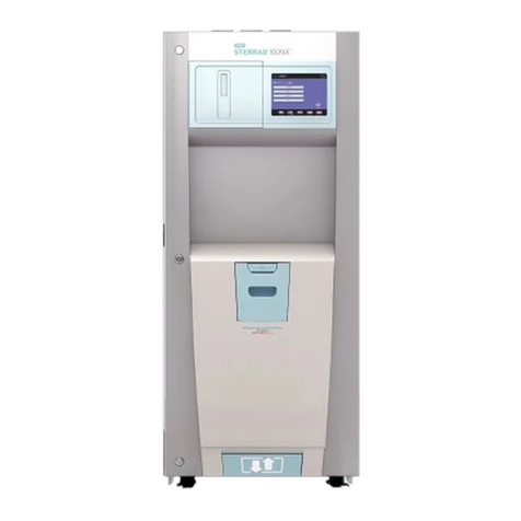
Figure 1. STERRAD®100NX® Sterilization System.

Introduction 1
STERRAD®100NX®Service Guide 9
Software
The sterilization process is controlled automatically by software. The
software controls and monitors the hardware through digital and analog
signals. Functions managed by software include:
•Timing
•Temperature/pressure measurement and control
•Sterilant delivery and vaporization
•Plasma power generation and measurement
•Hydrogen peroxide monitor
•Access to chamber is through the automatic door or doors
depending on system configuration.
Each parameter is part of a control loop in which information flows as
input from one of many sensors to the computer, where it is processed
and triggers an output signal that flows from the computer to an output
device. Through this system of feedback signals (input), analysis, and
response signals (output), the computer controls the entire sterilization
process. If any process parameter falls outside allowable ranges, the
software will cancel the cycle.
Note: The hydrogen peroxide monitor does not provide
feedback control to the sterilizer. However, the
monitor will cancel the cycle if the area under
the hydrogen peroxide concentration-time curve
or hydrogen peroxide rate constant does not
meet specifications.


Safety Information 2
STERRAD®100NX®Service Guide 11
Chapter 2.
Safety Information
Your safety is of primary concern to Advanced Sterilization Products.
This chapter provides information on safely servicing the STERRAD®
100NX®Sterilizer. You must read and understand the safety
information in this chapter before performing service on the
sterilizer. Always pay attention to the warnings, cautions, and notes
throughout this Service Guide.
Personal Safety and First Aid
ASP FIELD SERVICE ENGINEER REQUIREMENT
ALL ASP FIELD SERVICE ENGINEERS MUST WEAR SAFETY
GOGGLES WHEN SERVICING ASP PRODUCTS.
WARNING! HYDROGEN PEROXIDE IS CORROSIVE.
Concentrated hydrogen peroxide is corrosive to skin, eyes, nose, throat, lungs,
and the gastrointestinal tract. Always wear chemical resistant PVC (vinyl), or
nitrile gloves while removing items from the sterilizer following a cancelled
cycle, or if any moisture is noted on items in the load following a completed
cycle, or when handling used cassettes, or when handling used vacuum pump
oil.
WARNING! HYDROGEN PEROXIDE IS AN OXIDIZER.
Hydrogen peroxide is strong oxidizing agent and poses a hazard for fire,
explosion, or container rupture. Avoid allowing hydrogen peroxide to contact
organic materials, including paper, cotton, wood, or lubricants. Do not use or
store near heat or open flame. Shoes, clothing, or other combustible material
that have come into contact with hydrogen peroxide must be immediately and
thoroughly rinsed with water to avoid a potential fire hazard. In case of fire, use
only water to extinguish.

2 Safety Information
12 STERRAD®100NX®Service Guide
WARNING! RISK OF EYE INJURY.
Direct hydrogen peroxide contact with eyes can cause irreversible tissue
damage. If contact with eyes occurs, hold the eyes open and flush with large
amounts of water for at least 15-20 minutes. Remove contact lenses, if present,
and then continue rinsing the eyes. Consult a physician immediately after
flushing the eyes.
WARNING! RISK OF SKIN INJURY.
Direct hydrogen peroxide contact with the skin can cause severe irritation. Wear
chemical resistant PVC (vinyl) or nitrile gloves when handling used cassettes,
ejected cassettes, items from a cancelled cycle, items that have moisture present
after a completed cycle, or used vacuum pump oil. Immediately take off
contaminated clothing and rinse thoroughly with water to avoid potential fire
hazard and wash before re-use.
WARNING! RISK OF RESPIRATORY IRRITATION.
Inhalation of hydrogen peroxide mist can cause severe irritation of lungs, throat,
and nose. If inhalation occurs, move to the person to fresh air. If the person is
not breathing, call for emergency medical attention, or an ambulance, then give
artificial respiration, preferably mouth-to-mouth, if possible. Consult a
physician immediately.
WARNING! CONCENTRATED HYDROGEN PEROXIDE IS TOXIC.
Ingestion of hydrogen peroxide may be life-threatening. If swallowed, call a
“poison control” center or physician immediately for treatment advice. Have the
person drink plenty of water if the person is able to swallow. Do not give
anything by mouth to an unconscious person. Do not induce vomiting unless
instructed to do so by the poison control center or physician.
WARNING! HEATED STERILIZATION SURFACES
At the end of a cycle, the interior of the sterilizer may be hot. Do not touch the
inside of the chamber or door with your bare or gloved hands. Under certain
circumstances the outer surfaces of the vacuum pump may reach temperatures
above 70° C (158° F). Allow the sterilizer to cool before touching interior
surfaces.
WARNING! HYDROGEN PEROXIDE MAY BE PRESENT
If white residue is visible on a processed load, this is residue from the hydrogen
peroxide stabilizer. Wear chemical resistant PVC (vinyl), or nitrile gloves when
removing a load with visible white residue. White residue can be minimized by
making sure regular Planned Maintenance procedures are performed on the
system. The system informs the customer when Planned Maintenance is due.
WARNING! AVOID EXPOSURE TO ULTRAVIOLET LIGHT.
The hydrogen peroxide monitor uses an ultraviolet light source located inside
the chamber behind the door. To avoid eye injury, do not stare directly at the
ultraviolet light source for an extended period of time. Use UV-specific
protective eyewear if necessary.

Safety Information 2
STERRAD®100NX®Service Guide 13
WARNING! ELECTRIC SHOCK HAZARD.
High voltages are present inside the sterilizer. Contact with electrically
energized parts can cause injury or death. Turn OFF and unplug the sterilizer
before performing service tasks.
WARNING! RISK OF BREATHING DIFFICULTIES
On rare occasions, the outlet filter on the vacuum pump can prematurely fail. If
this occurs, you may see mist or what some users have described as “haze” or
“smoke” in the room where the sterilizer is operating. The chemical compos-
ition of the mist is primarily airborne mineral oil with trace amounts of other
compounds. Oil mist exposure may, theoretically, pose an increased risk to
people with certain respiratory conditions, such as asthma, and they should take
special precautions not to be exposed to the mist. If you observe these
conditions, personnel should leave the room as a precaution and discontinue use
of the sterilizer until it is repaired. Personnel should avoid working in the room
until the mist has cleared. Please note that all STERRAD®Sterilizers should be
used and installed in a well-ventilated environment (a minimum of 10 air
exchanges per hour).
Safe Maintenance/Device Safety
WARNING! TURN OFF THE STERILIZER PRIOR TO SERVICING
Always turn off the sterilizer prior to servicing unless the particular service
procedure requires electrical power.
WARNING! RISK OF INJURY OR DAMAGE TO THE VACUUM PUMP
AND STERILIZER.
Do not operate the vacuum pump if the outlet port is blocked or restricted in any
way. Failure to do so may result in over-pressurization of the oil housing and
cause it to rupture and violently release stored energy causing injury and
damage to the sterilizer.
WARNING! RISK OF INJURY OR DAMAGE TO THE VACUUM PUMP
Do not operate the vacuum pump without a metal blanking flange, or the
bellows and vacuum control valve properly connected to the chamber. Failure to
do so may result in contact with large quantities of exhausted vacuum pump oil,
severe over-heating, or seizure of the vacuum pump.
WARNING! RISK OF INJURY
Do not expose any part of your body to vacuum generated at the vacuum pump
port during pump-down, a severe injury may result.
WARNING! RISK OF INJURY OR DAMAGE TO STERILIZER
The sterilizer should not be used stacked with other equipment.

2 Safety Information
14 STERRAD®100NX®Service Guide
CAUTION: RISK OF DAMAGE TO THE STERILIZER. REPAIRS MUST
BE PERFORMED BY AUTHORIZED PERSONNEL
Repairs and adjustments should only be attempted by experienced technicians
who are fully trained to maintain and repair the STERRAD®100NX®Sterilizer.
Do not attempt to perform any adjustments or procedures on the sterilizer if you
have not been trained in an ASP-approved training facility by an ASP trainer.
CAUTION: RISK OF DAMAGE TO STERILIZER – VOIDING OF
WARRANTY
Use of unauthorized parts for maintenance or repair could cause personal injury,
result in costly damage or unit malfunction, and void the warranty.
CAUTION: RISK OF DAMAGE TO STERILIZER – NEED DEDICATED
POWER SOURCE
Warn the customer that they must not change the power source or relocate the
sterilizer to a new power source because the STERRAD®100NX®Sterilization
System requires a dedicated power source.
RISK OF DAMAGE TO STERILIZER– USE PROPER CLEANING
TOOLS
Do not clean the chamber door area with abrasives. The sterilization chamber
uses an O-ring vacuum seal to maintain a vacuum in the chamber. Never use
rough cleaning tools, such as a wire brush or steel wool, on the door housing or
chamber assembly. This could damage the seal.
Cassette Handling
CHECK FOR CASSETTE DAMAGE
Do not remove the cassette from the package if the indicator strip is red. Red
indicates that the cassette might have been damaged.
WARNING! RISK OF HYDROGEN PEROXIDE EXPOSURE
Do not remove the plastic wrapper from the cassette package if the indicator
strip is red. Red indicates that the cassette might have been damaged.
WARNING! RISK OF HYDROGEN PEROXIDE EXPOSURE
Do not handle used cassettes in the cassette collection box. Dispose of the
cassettes inside the cassette collection box per your facility’s procedures. If it is
necessary to handle a used cassette that is not in the cardboard sleeve, wear
chemical resistant gloves. Do not touch your gloved hands to your face or eyes.
FOR ROUTINE HANDLING, MINIMUM PPE REQUIREMENTS
INCLUDE APPROVED; (e.g., ANSI Z87.1), CHEMICAL SPLASH
GOGGLES, NITRILE CHEMICAL RESISTANT GLOVES, AND A
CHEMICAL RESISTANT; (e.g., polyolefin fiber), LAB COAT. Where
there is a risk of product contact with shoes, chemical resistant shoe

Safety Information 2
STERRAD®100NX®Service Guide 15
coverings are recommended. Where there is risk of product splashing into
eyes, an independent face shield must be worn in addition to chemical
splash goggles as authorized in 29 CFR 1910.133, applicable U.S. State
regulations, or the appropriate standards of Canada and its Provinces or EC
Member States (per European Standard EN 166).
Device Safety
WARNING: RISK OF INJURY OR DAMAGE TO THE STERILIZER
The STERRAD®100NX®Sterilizer should not be used stacked with other
equipment.
CAUTION: RISK OF DAMAGE TO THE STERILIZER.
Do not bend, nick, or damage the counterbalance metal tape in any way. Do not
use any tool to clamp it to another part. If the tape is damaged, it will bind in the
housing slit, further damage the part, and disrupt the door motion.
CAUTION: RISK OF DAMAGE TO THE LOAD.
Metal objects must not come into contact with the chamber walls, the door, or the
electrode. Contact with the walls, door, or electrode could damage the sterilizer or
the metal objects.
KNOW WHAT CAN BE PROCESSED
Before processing any item in the sterilizer, make sure you and your customers
know how the STERRAD®Sterilization Process will affect the item. Read,
understand, and follow the medical device manufacturers’ instructions for their
products. This guide is not intended to replace any medical device manufacturers’
instructions. If you or your customers have questions, or if you are in doubt about
the materials in any device, contact the medical device manufacturer or an ASP
Customer Representative for more information. Improper processing may limit
our liability for damage to processed instruments. Improper processing may also
violate the instrument warranty.
CAUTION: RF COMMUNICATIONS EQUIPMENT
Portable and mobile RF communications equipment can affect medical electrical
equipment.

2 Safety Information
16 STERRAD®100NX®Service Guide
Guidance And Declaration-Electromagnetic Emissions
The STERRAD®100NX®Sterilizer is intended for use in the electromagnetic environment specified
below. Assure that it is used in such an environment.
Emissions Test Compliance Electromagnetic Environment - Guidance
RF emissions CISPR 11 Group 1 The STERRAD®100NX®Sterilizer uses RF energy only
for its internal function. Therefore, its RF emissions are
very low and are not likely to cause any interference in
nearby electronic equipment.
RF emissions CISPR 11 Class A The STERRAD®100NX®Sterilizer is suitable for use in
all establishments other than domestic and those directly
connected to the public low-voltage power supply
network that supplies buildings used for domestic
purposes.
Harmonic emissions
IEC 61000-3-2
Class A
Voltage
fluctuations/flicker
emissions
IEC 61000-3-3
Complies
Warnings, Cautions, and Notes
Ì
□
Warnings and cautions are accompanied by symbols surrounded by a triangle or a
square and are printed in this manual in bold. Warnings indicate events or
conditions that can result in serious injury or death. Cautions indicate events or
conditions that can result in severe damage to the equipment.
Notes are printed in italics. Notes highlight specific information about the proper
use and maintenance of the STERRAD®100NX®Sterilization System.

Safety Information 2
STERRAD®100NX®Service Guide 17
Symbols Used on the Sterilizer or in
This Guide
Hot surfaces present.
Do not touch without protection.
Corrosive chemical present.
Use personal protective equipment.
Oxidizing chemical present
Use personal protective equipment. Do not expose to excessive heat or open
flame. Keep separate from flammable chemicals.
Toxic chemical present.
Avoid exposure, contact, or ingestion.
Ultraviolet (UV) light hazard.
Do not look at the light without UV eye protection.
High voltage hazard.
I/O On/Off.
Alternating current.

2 Safety Information
18 STERRAD®100NX®Service Guide
Safety Standards Compliance
The STERRAD®100NX®Sterilizer meets the following safety
standards:
•CAN/CSA-C22.2 No. 61010-1/R: 2009; Safety Requirements for
Electrical Equipment for Measurement, Control, and Laboratory
Use.
•UL 61010-1/R: 2008; Standard for Safety for Electrical
Equipment for Laboratory Use.
•IEC/EN 61010-1: 2001; Safety Requirements for Electrical
Equipment for Measurement, Control, and Laboratory Use.
•IEC/EN 61010-2-240: Particular requirements for sterilizers and
washer-disinfectors used to treat medical materials, 1st Ed., 2005.
•IEC/EN 60601-1-2: 2007 CLASS A; Medical Electrical
Equipment, Part 1: General Requirements for Safety, Section 2:
Collateral Standard: Electromagnetic Compatibility.
•EN 55011, Group I Class A limits, based on CISPR 11:2009,
Group I Class A limits (subset of EN 60601-1-2).

Functional Description 3
STERRAD®100NX®Service Guide 19
Chapter 3.
Functional Description
Overview of the Sterilization Process
The STERRAD®100NX® Sterilizer software interfaces with the
hardware through digital/analog input and output signals and through
serial communications via serial ports. The inputs monitor the
sterilization process while the outputs control the process. The process
occurs as follows:
1. The items to be sterilized are placed in the sterilization chamber, the
chamber door is closed, and a vacuum pump reduces the pressure in
the chamber.
2. A 59% aqueous solution of hydrogen peroxide is transferred from
the cassette and delivery system into the vaporizer/condenser where
it is concentrated and vaporized (Standard and Flex cycles) or
vaporized (Express and optional DUO cycles) before it is introduced
into the chamber.
3. A low frequency electric current is delivered to the chamber
electrode, causing the formation of a low-temperature gas plasma in
the chamber.
4. In the plasma state, the hydrogen peroxide vapor breaks apart into
reactive molecules that include free radicals.
5. The combined use of hydrogen peroxide and plasma safely and
rapidly sterilizes most medical instruments and materials without
leaving toxic residues.

3 Functional Description
20 STERRAD®100NX®Service Guide
Hydrogen Peroxide Concentration and
Delivery
Standard and Flex Cycles
During the hydrogen peroxide delivery step, hydrogen peroxide solution
is delivered into the vaporizer bowl after the system pumps below 200
torr. Additional air is removed from the chamber and from the
vaporizer/condenser by pulling a vacuum to a controlled pressure in the
vaporizer/condenser. At this time, the transfer valve is closed. Water is
removed from the 59% hydrogen peroxide solution by reducing the
pressure in the condenser. The pressure differential between the chamber
and the condenser creates the driving force to remove the water. During
this concentration step, the flow of H2O2vapor is restricted by an orifice
between the condenser and the chamber, creating lower chamber
pressure.
Once the controlled pressure is achieved in the condenser, the chamber
pressure is further reduced by closing the orifice with the transition
valve. The condenser temperature is increased and the concentrated
hydrogen peroxide vapor is then transferred into the chamber by opening
the transfer valve and the transition valve. This transfer step is followed
by the diffusion step (which occurs at atmospheric pressure), followed by
pressure reduction and plasma. The vent step then occurs which returns
the chamber to atmospheric pressure. This process occurs twice during a
complete sterilization cycle.
Express and Optional DUO Cycles
During the hydrogen peroxide delivery step, hydrogen peroxide solution
is delivered into the vaporizer bowl after the system pumps below 200
torr. Additional air is removed from the chamber by pulling a vacuum to
a controlled pressure in the chamber. During this time, the transfer and
transition valves are closed.
Once the controlled pressure is achieved in the chamber, the condenser
temperature is increased and 59% hydrogen peroxide vapor is then
transferred into the chamber by opening the transfer valve and the
transition valve. This transfer step is followed by the diffusion step
(which occurs at atmospheric pressure), followed by pressure reduction
and plasma. The vent step then occurs which returns the chamber to
atmospheric pressure. This process occurs twice during a complete
sterilization cycle.
Other manuals for Sterrad 100NX
1
Table of contents
Other Johnson & Johnson Laboratory Equipment manuals