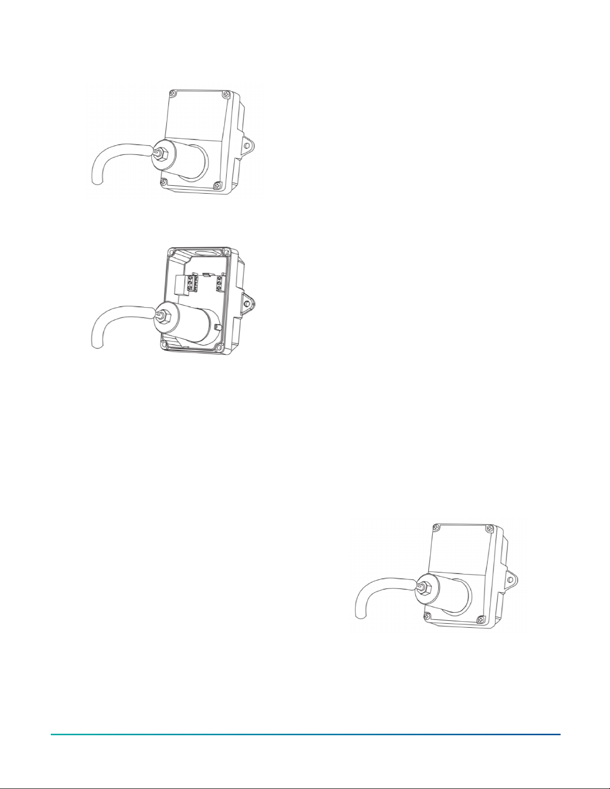
Figure 9: Calibration cap attached to external cover
port
Figure 10: Calibration cap attached to internal sensor
fixture
For local display, on a device with a 0 VDC to 10 VDC
output, use a voltmeter to measure between the OUT and
COM terminals to measure the output. For a device with
4 mA to 20 mA, place an ammeter in series of the output.
Disconnect the signal wire from the OUT terminal of the
CO sensor. Connect the + lead of the ammeter to the OUT
terminal of the CO sensor and connect the COM lead of
the ammeter to removed signal wire. Set ammeter to read
a 20 mA signal.
Continuously power the sensor for at least 30 min prior to
calibration. To calibrate the sensor, complete the following
steps:
1. Calibrate the sensor first in clean air with no CO gas
present. Adjust the ZERO pot on the sensor board
until you obtain a 0 VDC or 4 mA output depending
on device. For this case, adjust the output slightly
above 0 VDC or 4 mA and slowly reduce the output
signal to 0 VDC or 4 mA, depending on the device.
2. Monitor the output signal with the voltmeter
or ammeter that connects to the OUTPUT and
COMMON terminals.
3. Attach the gas supply.
4. Turn the regulator on/off knob fully off and attach
it to the 250 ppm gas bottle and firmly tighten it by
hand.
5. Moisten the sponge and squeeze out any excess
water.
6. Place the sponge in the cap so that it does not
touch the sensor and does not plug the hole in the
side of the cap.
7. Attach the cap to the fixture over the sensor.
8. Slowly turn the valve knob on the regulator to let
the gas flow. The regulator restricts the flow rate
to the specified 200 ml per min and the sponge
ensures the gas is in the right humidity range.
9. Wait for 5 min and adjust the SPAN pot on the
sensor board until the output value reads 250 ppm.
For the 0 ppm to 300 ppm device span, 250 ppm
equals 8.33 VDC or 17.33 mA, depending on the
model.
10. Close the valve on the tank and take the cap off
from the sensor. This completes calibration.
11. If the gas cap is too loose on the fixtures, wrap
electrical tape around the cap to tighten it.
NO2 transmitter calibration
About this task:
The NO2 transmitter features a simple snap-mount pre-
calibrated sensor PCB. You can replace the entire sensor
PCB with a new calibrated PCB without the removal of the
enclosure. This sensor swap requires no tools and you
can complete it in seconds. Disconnect the device wiring,
remove the old sensor PCB, snap in the new PCB, and
reconnect the device power. There is no need to make
any adjustments or apply gas to the transmitter using the
sensor swap method.
If necessary, calibrate the device or verify with NO2 gas.
This requires a field calibration kit that consists of a
bottle of gas, for example, 10 ppm NO2 in air, a tank
pressure regulator with flow restrictor, and the necessary
tubing with a calibration cap to cover the sensor. You can
calibrate at 68°F to 81°F (20°C to 27°C).
You can verify with gas without the removal of the device
cover. Use the calibration cap attached directly to the port
on the cover to apply gas and monitor the output value.
See Figure 11. Remove the device cover to perform an
actual calibration. In this case, the gas calibration cap
attaches to the sensor fixture inside the enclosure. See
Figure 12.
Figure 11: Calibration cap attached to external cover
port
GS3000 Indoor Gas Detection Sensor Series Installation Guide4