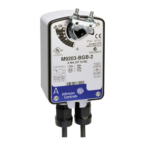
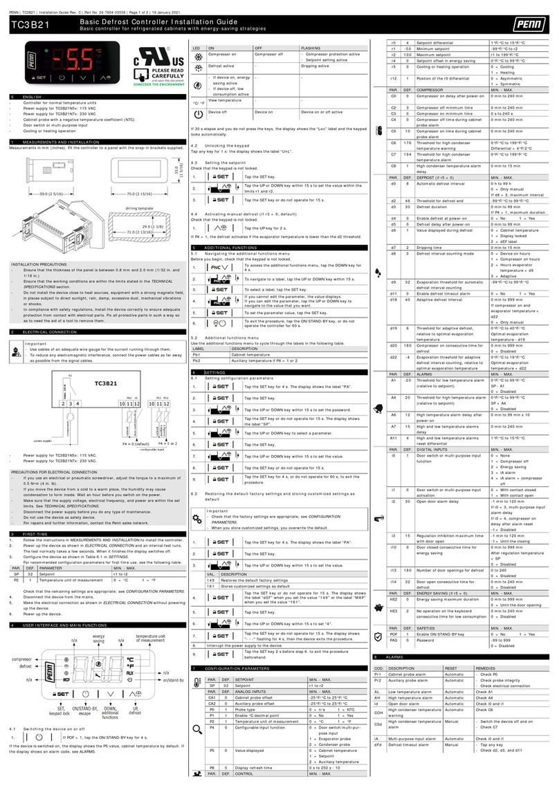
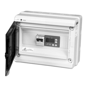
Johnson Controls EDA-8102 User manual
Other Johnson Controls Controllers manuals
Johnson Controls
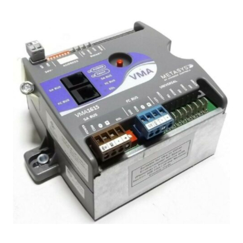
Johnson Controls VMA1615 User manual

Johnson Controls
Johnson Controls VA9208-AG Series User manual
Johnson Controls
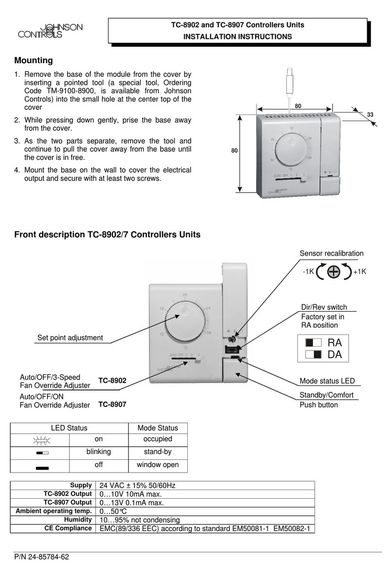
Johnson Controls TC-8902 User manual
Johnson Controls
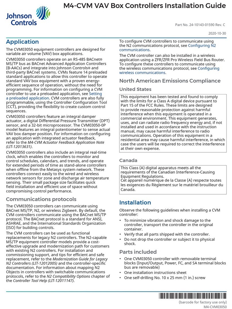
Johnson Controls CVM03050 User manual
Johnson Controls
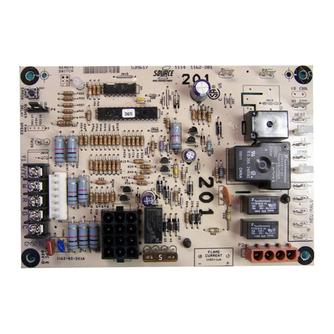
Johnson Controls S1-33103010000 User manual
Johnson Controls
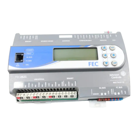
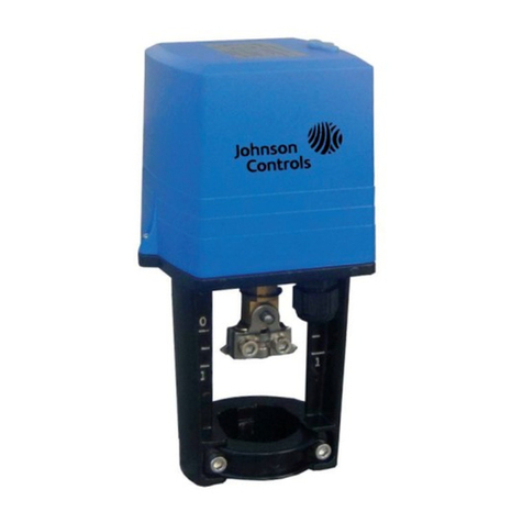
Johnson Controls FEC26 Series User manual
Johnson Controls
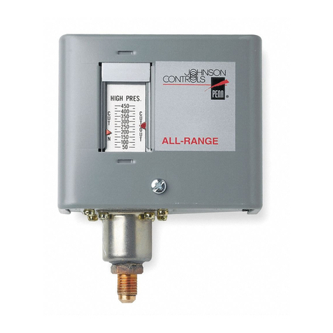
Johnson Controls VAP Series User manual
Johnson Controls
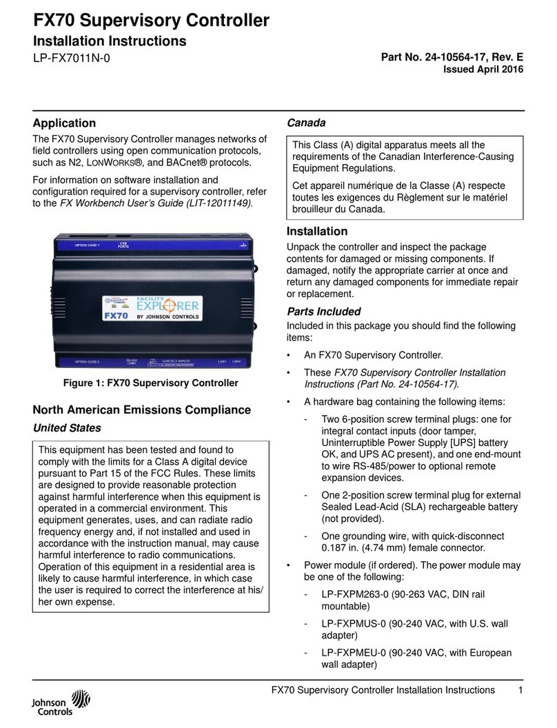
Johnson Controls PENN P70 Series User manual
Johnson Controls
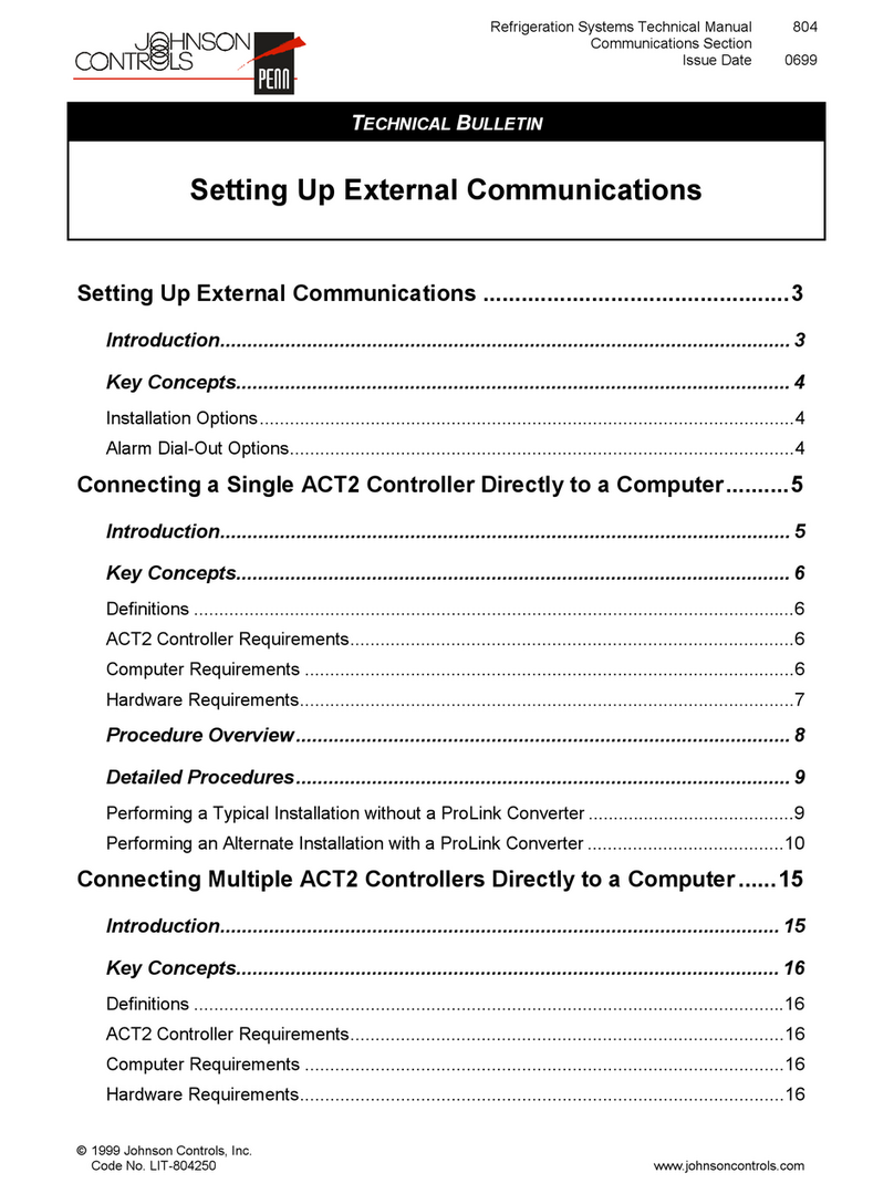
Johnson Controls FX70 User manual
Johnson Controls
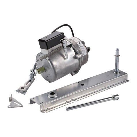
Johnson Controls PENN ACT2 Service manual
Johnson Controls
Johnson Controls DS-3153 User manual
Johnson Controls
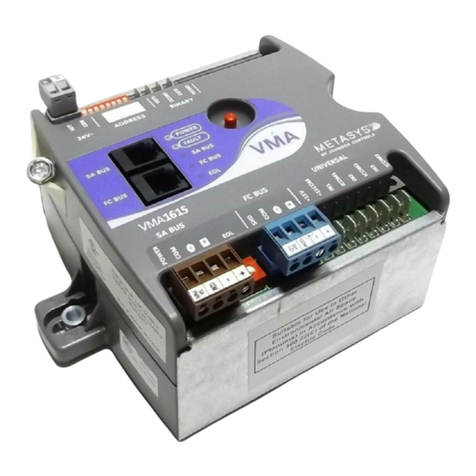
Johnson Controls VMA1615 User manual
Johnson Controls
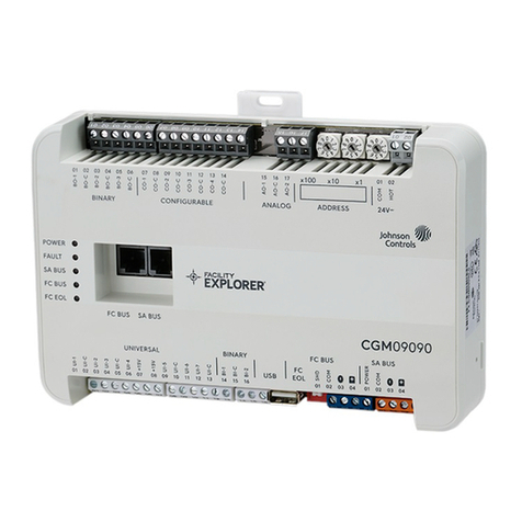
Johnson Controls F4-CG Series User manual

Johnson Controls
Johnson Controls VA9104-AGA-1S User manual
Johnson Controls
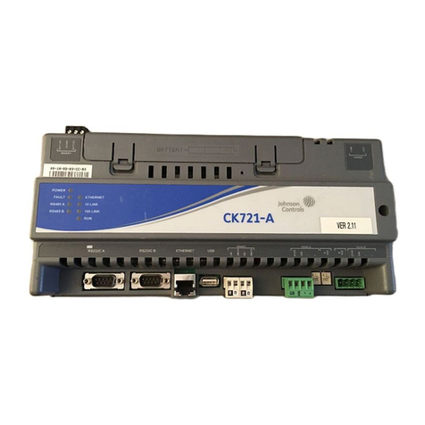
Johnson Controls CK721-A User manual
Johnson Controls
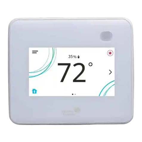
Johnson Controls TEC3000 Series User manual
Johnson Controls
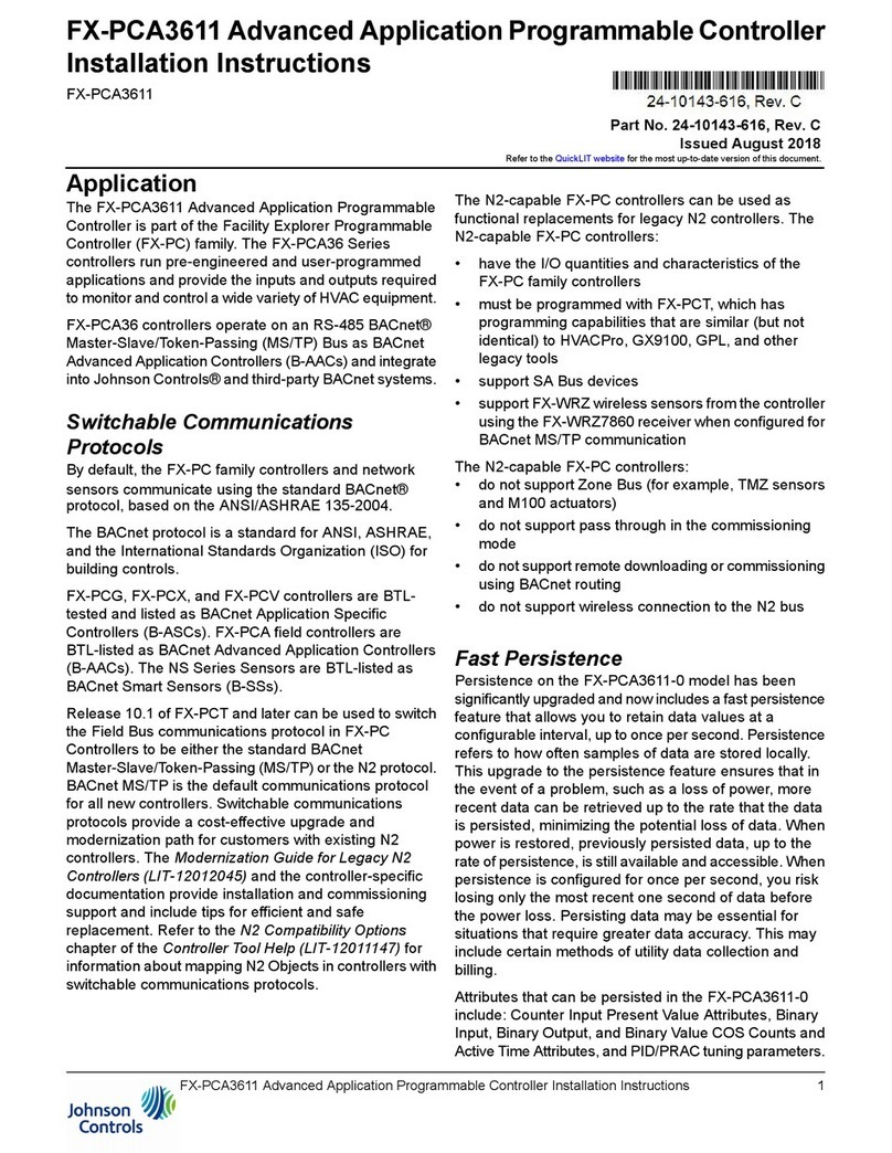
Johnson Controls FX-PCA3611 User manual
Johnson Controls
Johnson Controls VA7820-GG-1 Series User manual
Johnson Controls
Johnson Controls VA-77 Series User manual
Johnson Controls
Johnson Controls M4-CGM Series User manual
Popular Controllers manuals by other brands

Digiplex
Digiplex DGP-848 Programming guide

YASKAWA
YASKAWA SGM series user manual

Sinope
Sinope Calypso RM3500ZB installation guide

Isimet
Isimet DLA Series Style 2 Installation, Operations, Start-up and Maintenance Instructions

LSIS
LSIS sv-ip5a user manual

Airflow
Airflow Uno hab Installation and operating instructions
