manuals.online logo
Brands
  1. Home
  2. •
  3. Brands
  4. •
  5. Johnson Controls
  6. •
  7. Controllers
  8. •
  9. Johnson Controls EDA-2040 User manual

Johnson Controls EDA-2040 User manual

FANs 121, 1628.3, 268.1
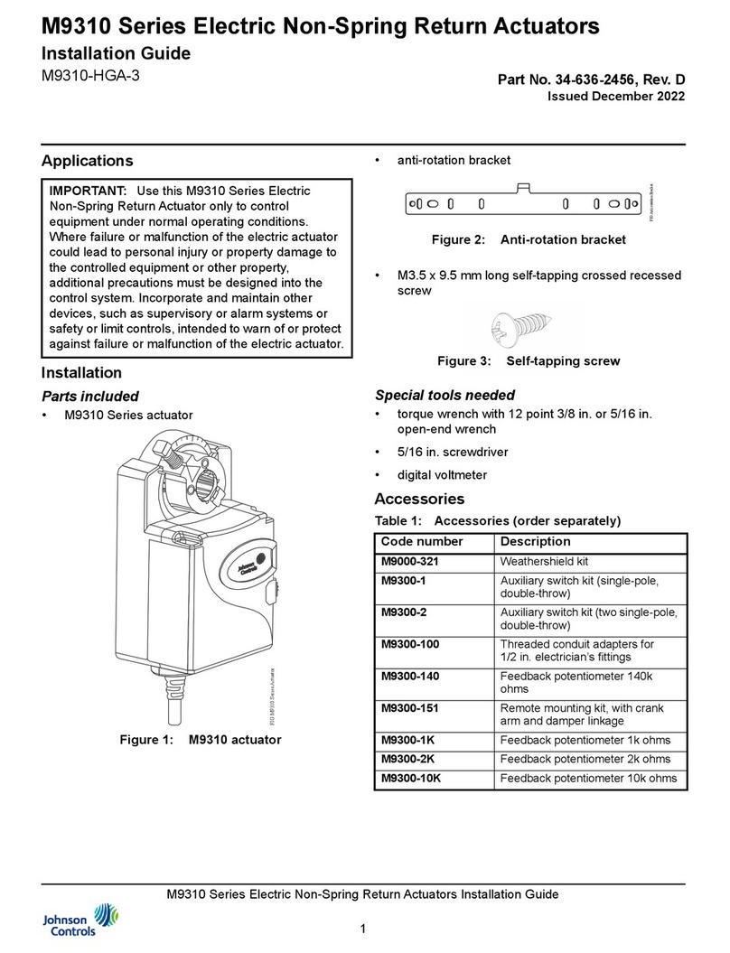
Technical Bulletin EDA-2040
Issue Date 0196
© 1996 Johnson Controls, Inc. 1
Part No. 34-619-18, Rev. E
Code No. LIT-121342
I
nstallation
The actuator is not position sensitive and can be
mounted in any convenient orientation. Wiring
terminals must be accessible and protected from
moisture and corrosive fumes. No extra mounting
brackets, linkage, or couplers are required for
standard mounting.
Note: The standard length shaft coupler must be
used when the EDA-2040 or ATP-2040 is
used with an EDA-2040-102 Switch Kit.
K
it Includes
●actuator
●No. 10 thread cutting tapping screw
●position scale
●position indicator
●CBL-2000 Wiring Harness (six female quick
connects with attached cables) for ATP-2040
Note: The CBL-2000 can also be ordered
separately.
T
ools Required
●screwdrivers, flat-blade (or nut driver) 5/16 in.
and No. 2 Phillips
●Allen wrench (90 degree hex key), 1/8 and
9/64 in. short series
●pliers
●drill, 5/32 in. (4 mm) drill bit
●screwdriver, No. 2 Phillips
●continuity tester (visual, audio, or DVM)
!
CAUTION: Equipment Damage Hazard.
Disconnect all power supplies
before wiring and follow the
National Electrical Code and all
local regulations to avoid
possible electrical shock or
damage to the equipment.
EDA-2040/ATP-2040 Electric Damper Actuator Installation
2 EDA-2040/ATP-2040 Electric Damper Actuator Installation Technical Bulletin
S
etting Actuator Stroke
To set the actuator stroke:
1. Make sure that the damper blade is visually
accessible or its position is permanently marked
on the end of the damper shaft as shown in
Figure 1.
Figure 1: Damper Position Icons
2. Grasp the damper shaft firmly with a pliers and
manually turn the damper in the direction of the
desired close off as shown in Figure 2. Consult
the box manufacturer’s information. Note the
rotation travel (30 to 90 degrees) and direction,
either Clockwise (CW) or Counterclockwise
(CCW), that is required to close the damper.
CW to
Open CCW to
Open
Damper
Shaft
VAV Box
Damper
Blade
Figure 2: Damper Rotation
3. Be aware that some box manufacturers do not
use 90 degree rotation. If the damper rotation is
less than 90 degrees, use a 9/64 in. hex key to
loosen the adjustable CCW end-stop on the
EDA-2040 enough to allow movement. Position
the end-stop as required by the application.
(See Figure 3.)
To CW
End-stop
To CCW
End-stop Ad
j
ustable
End-stop
OUT
GND
IN
(-) LO
DPT-2015-0
UP
Push
Gear
Release
Figure 3: Positioning to the End-stop
Note: Do not excessively loosen the end-stop as
this may permanently disable the
adjustment.
4. Tighten the end-stop between 20 and 25 in·lb.
5. Lift and hold the manual release lever, and turn
the actuator coupler until it contacts the
mechanical stop. Verify that both set screws are
accessible for tightening later.
IMPORTANT: The manual gear release lever will
not function if the actuator is driven
against a stop. Drive the actuator
1 degree off the stop to allow the
release to function.
Note: If the damper closes in the CCW direction,
the coupler should be rotated to the CCW
mechanical limit. If the damper closes in the
CW direction, the coupler should be rotated
to the CW mechanical limit.
6. If the damper shaft is longer than 2-1/4 inches,
use the standard mounting procedures. If the
damper shaft is shorter than 2-1/4 inches, use
the flush mounting procedures.
EDA-2040/ATP-2040 Electric Damper Actuator Installation Technical Bulletin 3
M
ounting
Standard
Observe ranges and limitations stated in the
Specifications section in the
EDA-2040/ATP-2040
Electric Damper Actuator Product Bulletin
in the
Damper and Actual Manual (FAN 268.1).
1. Verify that the damper blade is closed.
2. Place the actuator on the damper shaft so the
damper shaft protrudes through the actuator
coupler as shown in Figure 4.
VAV Box
(-)LO
OUT
GND
IN
UP
DPT-2015
Damper
Shaft
Figure 4: Standard Mounting
3. Place the actuator in the desired mounting
position 1/8 in. (3.2 mm) from the mounting
surface (shown in Figure 5) so that the wiring
connections are easily accessible.
1/8 in.
Gap
1/4 in. Barbed Ports
for Field Supplied
Tubin
g
EDA-2040 Mounted
to VAV Box
CBL-2000 Cable Harness
for Connection to VAV
Controller
Note: Upper port
is
(
-
)
LO.
1/4 in. O.D. Tubin
g
DPT-2015-0
Quick Connect
Terminals
Figure 5: Actuator Position
4 EDA-2040/ATP-2040 Electric Damper Actuator Installation Technical Bulletin
4. Use a punch to mark the position of the shoulder
washer on the mounting surface. The shoulder
washer should be at the center of the slot to
allow actuator movement during rotation.
(See Figure 6.)
OUT
GND
IN
(-) LO
DPT-2015-0
UP
Shoulder
Washer
CCW
COM
CW
Anti-rotation
Screw
Figure 6: Anti-rotation Screw with
Shoulder Washer
5. Drill a hole into the mounting surface through the
mark using a drill and 5/32 in. (4 mm) bit.
6. Position the actuator so the shoulder washer is
over the hole; insert the anti-rotation screw, as
shown in Figure 6, and tighten against the
washer.
7. Secure the coupler to the shaft evenly by using
a 1/8 in. hex key to bottom each coupler hex set
screw against the damper shaft.
Note: Maintain 1/8 in. clearance between the
mounting surface and actuator while
tightening the hex socket screws.
(See Figure 5.)
8. After bottoming each hex set screw against the
damper shaft, continue turning the hex key until
obtaining approximately a 30 degree deflection
of the wrench as illustrated in Figure 7
(40 to 65 in·lb). Repeat for the other hex set
screw.
!
CAUTION: Equipment Damage Hazard.
Do not remove anti-rotation
screw and force damper blade
closed using the actuator. This
puts additional stress on the
gear train and could reduce the
life of the actuator.
30°
(-)LO
OUT
GND
IN
UP
DPT-2015
Figure 7: Tightening Hex Set Screw
9. Lift and hold the manual release lever and turn
the shaft by hand to ensure that the damper can
rotate from its full closed to full open positions.
Proceed to the
Connections
section to continue
installation.
Flush
Note: This application will require the use of
one short shaft coupler (EDA-2040-1002 or
EDA-2040-1003) for each actuator.
1. Manually rotate the damper shaft to gently close
the damper blade.
Short
Damper
Shaft
O-rin
g
VAV Box
ATP-2040
Short Shaft
Coupler
(-)LO
OUT
GND
IN
UP
DPT-2015
Figure 8: Flush Mounting
2. Install the short shaft coupler into the damper
shaft with the O-ring away from the damper as
shown in Figure 8. The coupler should be 1/8 in.
(3.2 mm) away from the mounting surface.
3. Secure the coupler to the shaft evenly by using
a 1/8 in. hex key to bottom each hex set screw
of the coupler against the damper shaft.
Note: Maintain 1/8 in. clearance between the
mounting surface and the coupler while
tightening the hex set screws.
EDA-2040/ATP-2040 Electric Damper Actuator Installation Technical Bulletin 5
4. After bottoming each screw against the damper
shaft, continue turning the hex key until obtaining
approximately a 30 degree deflection of the
wrench as illustrated in Figure 7 (40 to 65 in·lb).
Repeat for the other hex set screw.
5. Place the actuator onto the coupler in the
desired mounting position 1/8 in. (3.2 mm) from
the mounting surface as shown in Figure 8 so
that the wiring connections are easily accessible.
6. Mark the center of the shoulder washer on the
mounting surface and then remove the actuator
from the coupler.
7. Drill a 5/32 in. (4 mm) hole into the mounting
surface through the mark.
8. Install the actuator onto the coupler so the
shoulder washer is over the hole, insert the
anti-rotation screw and tighten.
9. Connect a 24 VAC power source to the actuator
(cannot manually rotate a flush mounted
EDA-2040), and drive it to the full open and
closed positions to be sure of damper operation.
Proceed to the
Connections
section to continue
installation.
!
CAUTION: Equipment Damage Hazard.
Do not remove anti-rotation
screw and force damper blade
closed using the actuator. This
puts additional stress on the
gear train and could reduce the
life of the actuator.
Switch Kit
Note: An EDA-2040 actuator with bosses on the
housing is required for switch mounting.
(See Figure 9.)
Bosses
(-)
LO
OUT
GND
IN
UP
DPT-201
5
Insert
Screws
Switch Kit
Top
Switch Position
Indicator
Position
Scale
Bottom
Switch
Figure 9: Switch Kit Components
1. Install the standard coupler onto the actuator as
instructed in the
Mounting, Standard
section.
2. Position the switch kit so that the switch kit
coupler fits onto the actuator coupler.
3. Install the two screws to secure the switch kit to
the bosses on the actuator.
4. Verify that the damper is closed.
5. Verify that the position indicator points to the
damper closed position on the scale.
If the position indicator is not pointing to the
damper closed position, lift the scale from the
switch kit, reverse the scale, and install by
inserting its tabs into the recessed slots of the
switch kit. The position scale has two sides as
shown in Figure 10.
CCW
ToClose
CW
To Close
15°
5°
Close
Open
Close
Open
Figure 10: Position Scale Installation
6 EDA-2040/ATP-2040 Electric Damper Actuator Installation Technical Bulletin
Cam
COM NO NC
Switch Circuit
COM NO NC
Switch Circuit
Figure 11: Switch Circuits
6. Insert the long arm of a hex key into the slots of
the plastic coupler. Lift and hold the gear
release lever to rotate the coupler until the
pointer is located at the position to open/close a
switch depending on application.
Continuity
Tester
or
Ohmmeter
Figure 12: Tester Connections
7. Connect a continuity tester or ohmmeter to the
Common and Normally Open (NO)/Normally
Closed (NC) terminals of the top switch.
Top
Switch
Bottom
Switch
Cam
Teeth
Continuit
y
Tester
or
Ohmmeter
Slots
Figure 13: Tester Connections and Adjustment
8. Use the teeth of the top switch cam to rotate the
cam until a change in switch position is indicated
by the tester.
9. Rotate the switch kit coupler to verify switching
point.
10. Rotate the coupler to the position of desired
bottom switch point.
11. Repeat Steps 7 through 10 for the bottom
switch.
12. Verify that both switches activate at the desired
positions.
DPT-2015 on an EDA-2040 Actuator
Check the EDA-2040 cover for two inside mounting
bosses as shown in Figure 14. If there are none,
you must order the DPT-2015-MNT to mount the
DPT-2015-0 to your EDA-2040. The DPT-2015-0 is
also available assembled to the DPT-2015-MNT as
the DPT-2015-1. Follow the instructions provided
with either of these mounting kits or refer to the
DPT-2015-0 Differential Pressure Transmitter for
VAV Box Application Product/Technical Bulletin
in
the
Electronic Control Manual (FAN 216).
Inside Mountin
g
Bosses
Figure 14: EDA-2040 Shown with Two Inside
Mounting Bosses
EDA-2040/ATP-2040 Electric Damper Actuator Installation Technical Bulletin 7
C
onnections
Electrical Wiring
The ATP-2040 requires a 24 VAC control signal and
is compatible with a variety of controllers. All wiring
must be in accordance with National Electrical Code
and applicable local code requirements.
!
CAUTION: Disconnect all power supplies
to the system before wiring to
avoid damage to equipment or
possible electrical shock.
CCW COM CW IN GND OUT
24
VAC
W hite/ W hite W hite/ Red Black Blue
Oran
g
e Brown
EDA-2040 DPT-2015
24
VAC
CBL-2000 Wiring Harness
0.5-4.5
VDC
(
+
)
14.5-17
VDC
(
+
)
Common
(
-
)
Figure 15: Wiring Diagram
A CBL-2000 Wiring Harness is packaged with the
ATP-2040 or can be ordered separately for the
EDA-2040.
Air Pressure (ATP-2040 only)
The pressure sensing probe provided with the VAV
box must be connected to the DPT-2015 using field
supplied 1/4 in. O.D. tubing as follows:
1. Locate the pressure sensing probe provided with
the VAV box and cut two lengths of tubing for
connection to the barbed ports on the
DPT-2015. (See Figure 16.)
2. Connect the tubing from the pressure sensing
probe to the corresponding high and low,
indicated as (-) LO, pressure ports on the
DPT-2015.
!
CAUTION: Equipment Damage Hazard.
Overpressure limit is 15 in.
W.C. Do not blow into ports
to test the operation as this
may damage the sensing
element.
Note: If the pressure ports are not pointing down,
route the tubing so a portion of it is lower
than the DPT-2015. This creates a trap that
prevents any condensation from entering the
sensor. Also, do not make any sharp bends
in the tubing. This could collapse the tube
and block the pressure path.
EDA-2040 Mounted
to VAV Box
DPT-2015-0
1/4 in. Barbed Ports
for Field Supplied
Tubin
g
CBL-2000 Cable Harness
for Connection to VAV
Controller
Note: Upper port
is
(
-
)
LO.
1/4 in. O.D. Tubin
g
Figure 16: Air Pressure Connectors
C
ommissioning
EDA-2040
After wiring is completed, apply power to the
controller and provide signals to the actuator to drive
it at least one complete cycle open and close.
DPT-2015
1. Perform the checkout procedure provided in the
controller instructions to ensure proper operation
of the transmitter.
2. When used with a Johnson Controls VAV Series
controller, the DPT-2015 must be set up and
zeroed using HVAC PRO for Windows. Refer
to the
Variable Air Volume Controller Technical
Bulletin
in the
Controllers Technical Manuals
(FANs 636.3 or 1628.2)
for details.
IMPORTANT: Final commissioning should be
performed when the transmitter is
at normal operating temperatures
and mounted in its normal
operating position.
8 EDA-2040/ATP-2040 Electric Damper Actuator Installation Technical Bulletin
T
roubleshooting and Inspection
EDA-2040
1. Make sure the actuator/transmitter is mounted
on the duct and at ambient temperature.
2. Check that all electrical connections are
complete and power is applied.
3. Verify that the flow pickups are connected to the
DPT-2015.
4. Perform the checkout procedures described in
the
Variable Air Volume Controller Technical
Bulletin
in the
Controllers Technical Manuals
(FANs 636.3 or 1628.2)
to verify operation of the
actuator/transmitter.
5. Verify that the damper is fully opening and
closing.
DPT-2015
The DPT-2015 must be auto zeroed at the Johnson
Controls VAV controller. If not operating properly:
1. Make sure the air lines on the DPT-2015 are
connected to their respective high and low ports.
2. Check voltage to ensure it is within the
14.5 to 17 VDC range and the polarity is correct.
3. Disconnect the air lines from the high and low
ports, and place a voltmeter across terminals
OUT and GND. With power applied to the
DPT-2015, if the output is not between
0.4 and 0.6 volts, the transmitter is defective
and should be replaced.
Note: If the transmitter is not mounted vertically,
voltage readings may increase or decrease
by 0.1 volts.
EDA-2040/ATP-2040 Electric Damper Actuator Installation Technical Bulletin 9
Notes
Controls Group
507 E. Michigan Street
P.O. Box 423
Milwaukee, WI 53201 Printed in U.S.A.

This manual suits for next models

1

Other Johnson Controls Controllers manuals
Johnson Controls TC-8902 User manual

Johnson Controls

Johnson Controls TC-8902 User manual

Johnson Controls M9108-A-1N Series User manual

Johnson Controls

Johnson Controls M9108-A-1N Series User manual

Johnson Controls M9116-GG-1N4 Series User manual

Johnson Controls

Johnson Controls M9116-GG-1N4 Series User manual

Johnson Controls M9102 GA-1S Series User manual

Johnson Controls

Johnson Controls M9102 GA-1S Series User manual

Johnson Controls F4-CG Series User manual

Johnson Controls

Johnson Controls F4-CG Series User manual

Johnson Controls T-5800 Series Use and care manual

Johnson Controls

Johnson Controls T-5800 Series Use and care manual

Johnson Controls FX Supervisory Controller RS-485 Card User manual

Johnson Controls

Johnson Controls FX Supervisory Controller RS-485 Card User manual

Johnson Controls TEC3010 User manual

Johnson Controls

Johnson Controls TEC3010 User manual

Johnson Controls M9220-Bxx-3 User manual

Johnson Controls

Johnson Controls M9220-Bxx-3 User manual

Johnson Controls TEC3620 Series User manual

Johnson Controls

Johnson Controls TEC3620 Series User manual

Johnson Controls VG1600 Series User manual

Johnson Controls

Johnson Controls VG1600 Series User manual

Johnson Controls EDA-8000 Manual

Johnson Controls

Johnson Controls EDA-8000 Manual

Johnson Controls PENN ACT2 Service manual
Johnson Controls

Johnson Controls PENN ACT2 Service manual

Johnson Controls SE-ZEC510-1 User manual

Johnson Controls

Johnson Controls SE-ZEC510-1 User manual

Johnson Controls Metasys MS-FEU1610-0U User manual

Johnson Controls

Johnson Controls Metasys MS-FEU1610-0U User manual

Johnson Controls M9200 Series User manual

Johnson Controls

Johnson Controls M9200 Series User manual

Johnson Controls TEC3010 User manual

Johnson Controls

Johnson Controls TEC3010 User manual

Johnson Controls FEC16 Series User manual

Johnson Controls

Johnson Controls FEC16 Series User manual

Johnson Controls MS-FEC1611-1U User manual

Johnson Controls

Johnson Controls MS-FEC1611-1U User manual

Johnson Controls Tyco Kantech KT-400 Quick start guide

Johnson Controls

Johnson Controls Tyco Kantech KT-400 Quick start guide

Johnson Controls M9220-GG-3 Series User manual

Johnson Controls

Johnson Controls M9220-GG-3 Series User manual

Johnson Controls FEC26 Series User manual

Johnson Controls

Johnson Controls FEC26 Series User manual

Johnson Controls tyco iSTAR Edge G2 Operator's manual

Johnson Controls

Johnson Controls tyco iSTAR Edge G2 Operator's manual

Johnson Controls A25CN Series Guide

Johnson Controls

Johnson Controls A25CN Series Guide

Popular Controllers manuals by other brands

Grozone Control Dual Zone CO2 Controller manual

Grozone Control

Grozone Control Dual Zone CO2 Controller manual

Westinghouse IWB-PC02 user manual

Westinghouse

Westinghouse IWB-PC02 user manual

OPTO 22 SNAP-PAC-S1 user guide

OPTO 22

OPTO 22 SNAP-PAC-S1 user guide

ABB AC 800M installation manual

ABB

ABB AC 800M installation manual

Tektronix 7S12 instruction manual

Tektronix

Tektronix 7S12 instruction manual

Johnson JCRL120P instruction manual

Johnson

Johnson JCRL120P instruction manual

Samson 3275A Mounting and operating instructions

Samson

Samson 3275A Mounting and operating instructions

Shihlin electric SA3 Series instruction manual

Shihlin electric

Shihlin electric SA3 Series instruction manual

PDC spas Accent Operation guide

PDC spas

PDC spas Accent Operation guide

Nordson EFD PICO Touch operating manual

Nordson EFD

Nordson EFD PICO Touch operating manual

ICP GDT8514RZ Installation

ICP

ICP GDT8514RZ Installation

Toss ROPEX RESISTRON RES-407 operating instructions

Toss

Toss ROPEX RESISTRON RES-407 operating instructions

ALVEO3D V2 instruction manual

ALVEO3D

ALVEO3D V2 instruction manual

ETC Echo Inspire Station Programming guide

ETC

ETC Echo Inspire Station Programming guide

Phocos ECO-N-T user manual

Phocos

Phocos ECO-N-T user manual

Geco GH10TA user manual

Geco

Geco GH10TA user manual

dixell EMERSON XR70C Installing and operating instructions

dixell

dixell EMERSON XR70C Installing and operating instructions

Jandy AquaLink Touch Installation and operation manual

Jandy

Jandy AquaLink Touch Installation and operation manual

manuals.online logo
manuals.online logoBrands
  • About & Mission
  • Contact us
  • Privacy Policy
  • Terms and Conditions

Copyright 2025 Manuals.Online. All Rights Reserved.