manuals.online logo
Brands
  1. Home
  2. •
  3. Brands
  4. •
  5. Omnio
  6. •
  7. Controllers
  8. •
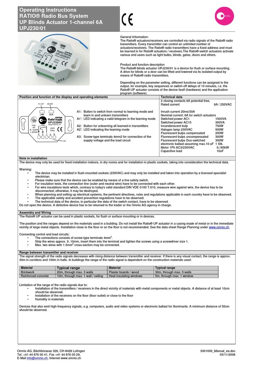
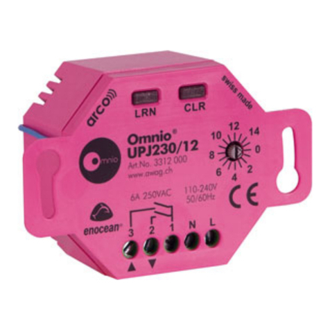
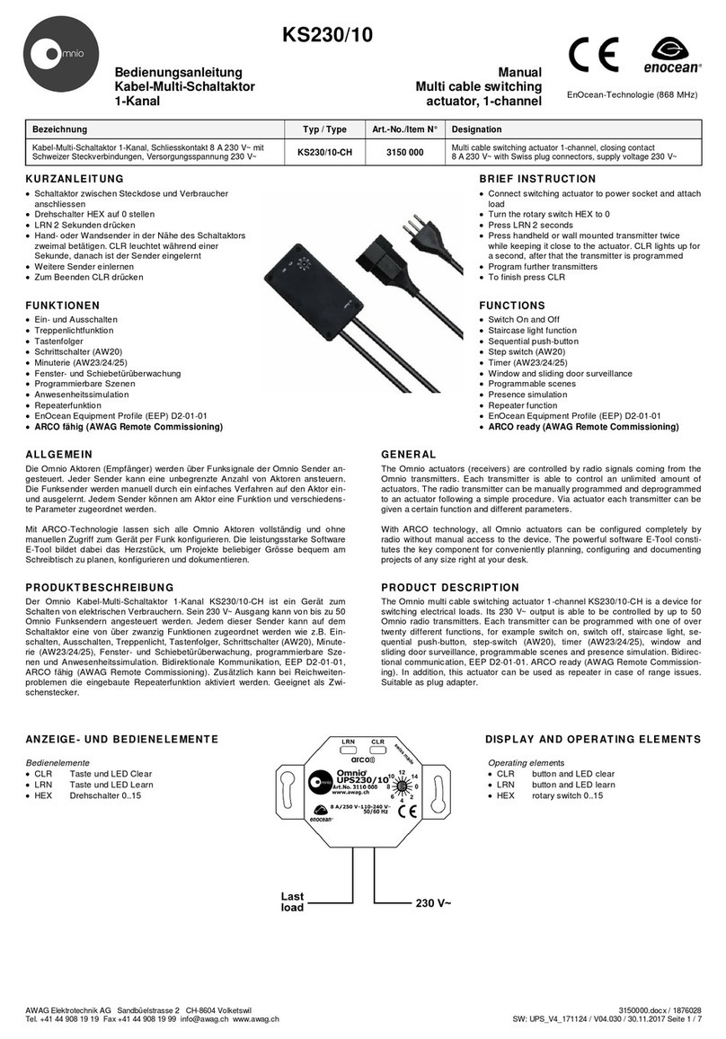
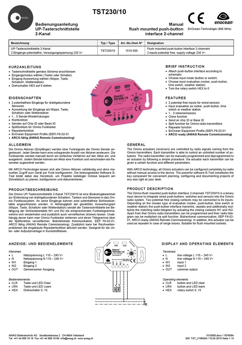
  9. Omnio APG03B-RS485 User manual

Omnio APG03B-RS485 User manual

AWAG Elektrotechnik AG Sandbüelstrasse 2 CH-8604 Volketswil
Tel. +41 44 908 19 19 Fax +41 44 908 19 99 [email protected]
www.awag.ch
APG03B
Bedienungsanleitung
Funk-
Gateway bidirektional RS485
Bezeichnung
Funk-Gateway bidirektional RS485
Versorgungsspannung 10-30 V DC
ALLGEMEIN
Die Omnio Aktoren (Empfänger) werden über Funksignale
der Omnio Sender angesteuert. Jeder Sender kann eine
unbegrenzte Anzahl von Aktoren ansteuern. Die Funksender
werden durch ein einfaches Verfahren auf den Aktor ein-
und
ausgelernt. Jedem Sender können am Aktor eine Funktion
und verschiedenste Parameter zugeordnet werden.
FUNKTIONEN
•Bidirektionales EnOcean – RS485 Gateway
•Eingangsfilter
•Repeaterfunktion
•Einfache Parametrierung über Omnio E-Tool Software
•EnOcean Serial Protocol 2
•Einstellbare Basisadresse
•Übertragungsrate über Jumper einstellbar
•RS485 Abschlusswiderstand über Jumper zuschaltbar
PRODUKTBESCHREIBUNG
Das bidirektionale Funk-Gateway APG03B-RS485
dient als Bindeglied
EnOcean Geräten und Systemen mit einer
RS485 Schnittstelle. Alle
Gateway empfangenen gültigen EnOcean Funkt
elegramme werden auf d
RS485 Schnittstelle weitergeleitet und umgekehrt.
Die Verbindung auf dem RS485-Bus erfolgt über ein
abgeschirmtes,
Kabelpaar im Halbduplex Verfahren. Implementiert ist
das EnOcean Serial
Protocol 2 (ESP2)
, dadurch können mehrere Gateways über den gleichen Bus mit
einem Klient kommunizieren. Das neuere ESP3 lässt dies nicht zu und wird
deshalb nicht unterstützt.
Um den Datenverkehr zu minimieren, ist das Gateway mit einem Eingangsfilter
ausgerüstet. Bei ak
tiviertem Filter werden nur Telegramme von im Gateway
eingelernten Geräten weitergeleitet.
INSTALLATION
Das Gerät
ist für feste Installation in Innenräumen (trockene Räume) unter Ein
haltung der technischen Daten und gängigen Sicherheitsvorschriften bestimmt.
Die Speisung erfolgt über ein separates Netzteil.
Das Gateway
wird über die Klemmen K1 (GND) und K2 (+) mit einem Netzteil
30 V DC
verbunden. Die grüne LED L1 zeigt an, ob die Spannungsversorgung
korrekt angeschlossen ist.
Über die Klemmen K3 (RS485 Datenleitung B/-
), K4 (RS485
und K5 (RS485 Abschirmung
) wird das Gateway an den RS485
angeschlossen. Mit dem Jumper J3 kann optional ein Abschlusswiderstand von
120 Ωzugeschaltet werden. Die grüne LED L3
zeigt durch kurzes Flackern den
vom Gateway übertragenen Datenverkehr an.
ANZEIGE- UND BEDIENELEMENTE
Klemmen
•K1 Speisung (-) GND
•K2 Speisung (+) 10-30 V DC
•K3 RS485 Datenleitung B/-
•K4 RS485 Datenleitung A/+
•K5 RS485 Abschirmung
Leuchtdioden
•L1 Speisung
•L2 Datenkommunikation EnOcean
•L3 Datenkommunikation RS485 /
Betriebsart
•L4 Störung / Repeater Level 1
•L5 Zur freien Verwendung /
Repeater Level 2
Tasten
•S3 Betriebsart
•S4 Repeater
Jumper
•J1 Baudrate
•J2 Baudrate
•J3 RS485 Abschlusswiderstand 120 Ω
www.awag.ch
APG03B
-RS485
Manual
Gateway bidirektional RS485
Gateway bidirectional RS485
Typ / Type Art.-No./Item N° Designation
APG03B-RS485 6011 000
Gateway bidirectional RS485
supply voltage 10-
30 V DC
unbegrenzte Anzahl von Aktoren ansteuern. Die Funksender
und
GENERAL
The Omnio
actuators (receivers) are controlled by radio signals
coming from the Omnio transmitters. Each transmitter is able to
control an unlimited amount of actuators. The radio transmitter
can be programmed and deprogrammed to an actuator following a
simple proc
edure. Via actuator each transmitter can be given a
certain function and different parameters.
FUNCTIONS
•Bidirectional
EnOcean
•Input filter
•Repeater function
•
Simple configuration with
•EnOcean
Serial Protocol 2
•Programmable
base address
•
Adjustable transmission rate with jumper
•RS485
termination resistor
dient als Bindeglied
zwischen
RS485 Schnittstelle. Alle
vom
elegramme werden auf d
ie
abgeschirmtes,
verdrilltes
das EnOcean Serial
, dadurch können mehrere Gateways über den gleichen Bus mit
einem Klient kommunizieren. Das neuere ESP3 lässt dies nicht zu und wird
Um den Datenverkehr zu minimieren, ist das Gateway mit einem Eingangsfilter
tiviertem Filter werden nur Telegramme von im Gateway
ist für feste Installation in Innenräumen (trockene Räume) unter Ein
-
haltung der technischen Daten und gängigen Sicherheitsvorschriften bestimmt.
wird über die Klemmen K1 (GND) und K2 (+) mit einem Netzteil
10 -
verbunden. Die grüne LED L1 zeigt an, ob die Spannungsversorgung
), K4 (RS485
Datenleitung A/+)
) wird das Gateway an den RS485
-Bus
angeschlossen. Mit dem Jumper J3 kann optional ein Abschlusswiderstand von
zeigt durch kurzes Flackern den
PRODUCT DESCRIPTION
The bidirectional radio gateway
APG03B
devices and systems with a RS485 interface.
passed on to the RS485 bus and vice versa.
The connection on the RS485 bus
is made
half-
duplex mode. The EnOcean serial protocol 2 (ESP 2) has been implemented,
allowing more than one gateway
to communicate
RS485 bus. The newer ESP 3 doesn’t
The gateway is equipped with an input filter to limit data traffic
If the filter is activated, only those
telegrams of devices known to the gateway are
passed on, thus reducing data traffic.
INSTALLATION
This device is suitable for indoor
installation
technical data and common safety regulations.
power supply.
The gateway is connected to a 10 –
30 V DC power supply
(GND) and K2 (+). The green LE
D indicates a correctly installed power supply.
The RS485 bus cable
is connected to terminal K3 (Data B
K5 (shield). A 120 Ω
termination resistor can be activated with a jumper (J3)
necessary. With flickering the green
passing the gateway.
SIGNALS AND CONTROL
Terminals
•K1 Power (
-
•K2 Power
(+) 10
•K3 RS485
data line
•K4 RS485
data line
•K5 RS485
shield
LEDs
•L1 Power
•L2
EnOcean
•L3 RS485
data communication
operating
•L4 Error /
repeater level
•L5
For free usage
repeater level
Buttons
•S3
Operating mode
•S4 R
epeater
Jumper
•J1
Baud rate
•J2
Baud rate
•J3 RS485
termination resistor
6011000.docx / 1876044
V04.001 / 08.04.2016 Seite 1 / 6
Manual
Gateway bidirectional RS485
30 V DC
actuators (receivers) are controlled by radio signals
coming from the Omnio transmitters. Each transmitter is able to
control an unlimited amount of actuators. The radio transmitter
can be programmed and deprogrammed to an actuator following a
edure. Via actuator each transmitter can be given a
certain function and different parameters.
EnOcean
– RS485 gateway
Simple configuration with
Omnio E-Tool
Serial Protocol 2
base address
Adjustable transmission rate with jumper
termination resistor
connectible with jumper
APG03B
-RS485 serves as link between EnOcean
devices and systems with a RS485 interface.
All valid EnOcean radio signals are
passed on to the RS485 bus and vice versa.
is made
over a shielded cable (twisted pair) in
duplex mode. The EnOcean serial protocol 2 (ESP 2) has been implemented,
to communicate
with a client over the same
RS485 bus. The newer ESP 3 doesn’t
allow this and is therefore not supported.
The gateway is equipped with an input filter to limit data traffic
on the RS485 bus.
telegrams of devices known to the gateway are
installation
s (dry rooms) in compliance with the
technical data and common safety regulations.
The gateway needs a separate
30 V DC power supply
through terminal K1
D indicates a correctly installed power supply.
is connected to terminal K3 (Data B
/-), K4 (Data A/+) and
termination resistor can be activated with a jumper (J3)
when
LED L3 indicates data traffic on the bus
SIGNALS AND CONTROL
ELEMENTS
-
) GND
(+) 10
-30 V DC
data line
B/-
data line
A/+
shield
EnOcean
data communication
data communication
/
operating
mode
repeater level
1
For free usage
/
repeater level
2
Operating mode
epeater
Baud rate
Baud rate
termination resistor
120 Ω
EnOcean-Technologie (868 MHz )
AWAG Elektrotechnik AG Sandbüelstrasse 2 CH-8604 Volketswil 6011000.docx / 1876044
Tel. +41 44 908 19 19 Fax +41 44 908 19 99 [email protected] www.awag.ch V04.001 / 08.04.2016 Seite 2 / 6
ÜBERTRAGUNGSRATE
Die Einstellung der Übertragungsrate erfolgt mit
den Jumpern J1 und J2. Die empfohlene
Baudrate beträgt 38400 Baud. Alle Gateways
am gleichen RS485-Bus müssen dieselbe
Baudrate aufweisen.
TRANSMISSION RATE
The data transmission rate can be adjusted with jumper J1
and J2. The recommended value is 38400 baud. All
devices on the same RS485 bus must use the same
transmission rate.
REPEATER
Bei Reichweitenproblemen kann der Repeater manuell oder mit dem Omnio E-
Tool aktiviert werden. Dies betrifft nur EnOcean Funktelegramme und hat keine
Auswirkung auf die Gatewayfunktion oder den RS485-Bus.
Wichtig: Um keinen unnötigen Funkverkehr zu erzeugen, sollte der Repeater
nur bei Bedarf eingeschaltet werden.
REPEATER MANUELL ZUSCHALTEN
Durch langen Druck (ca. 2 s) auf die Taste S4 wird der Repeater Level 1
eingeschaltet, und die rote LED L4 leuchtet während 5 Sekunden auf. Alle
gültigen, unverstärkten EnOcean Funktelegramme werden verstärkt.
Durch erneuten Druck (ca. 2 s) auf S4 wird der Repeater Level 2 eingeschaltet,
und die grüne LED L5 leuchtet während 5 Sekunden auf. Alle gültigen EnOcean
Funktelegramme werden verstärkt. Ein Telegramm kann höchstens zweimal
verstärkt werden.
Durch nochmaligen Druck (ca. 2 s) auf S4 wird der Repeater ausgeschaltet, und
beide LEDs L4 und L5 leuchten während 5 Sekunden auf.
STÖRANZEIGE L4
Störungen werden mit zyklischen Blinkpaketen während 30 Sekunden angezeigt
und danach automatisch zurückgesetzt.
Zweimal blinken: Kein ACK-Telegramm vom Master empfangen
Dreimal blinken: Empfangspuffer voll
Fünfmal blinken: Eingangsfilter voll
EINGANGSFILTER
Im Gateway eingelernte Geräte werden im Eingangsfilter gespeichert. Ist dieser
Filter aktiv, werden nur Telegramme von eingelernten Geräten weitergeleitet,
was den Datenverkehr erheblich minimiert. Sind mehrere Gateways am gleichen
RS485-Bus angeschlossen, muss dieser Filter zwingend aktiv sein, damit keine
Telegrammkollisionen entstehen. Ausserdem darf jedes Gerät nur in einem
einzigen Gateway eingelernt sein.
Der Eingangsfilter wird mit dem Omnio E-Tool oder softwaremässig ein- und
ausgeschaltet, siehe weiter unten.
BETRIEBSART
Das Gateway kennt zwei Betriebsarten: Standard und Einlernen. Im normalen
Gebrauch wird die Betriebsart Standard verwendet.
Durch langes Drücken (ca. 2 s) der Taste S3 wird in die Betriebsart Einlernen
gewechselt, und die grüne LED L3 leuchtet. Geräte werden manuell oder mit
dem Omnio E-Tool eingelernt.
Durch nochmaligen Druck (ca. 2 s) auf S3 wird das Gateway wieder in die
Betriebsart Standard versetzt und LED L3 erlischt.
ENOCEAN GERÄTE MANUELL EINLERNEN
Das Gateway muss sich in der Betriebsart Einlernen befinden, LED 3 leuchtet.
Jetzt wird am einzulernenden EnOcean Gerät die Einlernsequenz gemäss
untenstehender Tabelle befolgt, worauf LED L3 für 1 Sekunde erlischt.
EnOcean Gerät Einlernsequenz
Wandsender
Handsender
Key-Card-Schalter
Taste drücken
Fensterkontakt LRN-Taste drücken
Fenster-/Türgriff Griff betätigen
Omnio RTF16x LRN-Taste drücken
CO
2
-Sensor Sensor einschalten und 15 s warten
Omnio UP-Aktoren
Omnio Kabel-Aktoren 13 – LRN (2 s) – 11 – LRN – 0
Wichtig: Nach dem Einlernvorgang muss man das Gateway wieder in die
Betriebsart Standard setzen.
GERÄTE MANUELL LÖSCHEN
Geräte werden manuell oder mit dem Omnio E-Tool gelöscht.
Befindet sich das Gateway in der Betriebsart Standard, werden durch langes
Drücken (ca. 6 s) der Taste S3 alle eingelernten Geräte gelöscht. Die grüne LED
L3 blinkt kurz auf, danach schaltet das Gateway automatisch auf die Betriebsart
Einlernen um.
Durch nochmaligen Druck (ca. 2 s) auf S3 wird das Gateway wieder in die
Betriebsart Standard versetzt und die LED L3 erlischt.
REPEATER
In case of problems with the reception quality, the repeater function can be
activated manually or by Omnio E-Tool. This affects only EnOcean radio
telegrams and doesn’t influence the gateway functions or the RS485 bus.
Important: To prevent unnecessary radio traffic, the repeater should only be
activated when indicated.
MANUAL ACTIVATION OF THE REPEATER
By pressing the button S4 for approx. 2 s the repeater level 1 is activated, and
the red LED L4 illuminates for 5 seconds. All valid original EnOcean radiograms
are repeated by the gateway.
By pressing the button S4 again for approx. 2 s the repeater level 2 is activated,
and the green LED L5 illuminates for 5 seconds. All valid EnOcean radiograms
are repeated by the gateway. An EnOcean radiogram can only be repeated
twice.
By pressing the button S4 a third time the repeater is deactivated and both LED
L4 and L5 illuminate for 5 seconds.
ERROR LED L4
Errors are indicated with L4 flashing for 30 seconds, then the error is reset
automatically.
Blinking 2 times: No ACK telegram received by the master
Blinking 3 times: Receive buffer full
Blinking 5 times: Input filter full
INPUT FILTER
Programmed devices are stored in the gateway’s input filter. When activated,
only telegrams of programmed devices are passed on by the gateway, thus
significantly reducing data traffic. If more than one gateway is connected to the
same RS485 bus, activation of this filter is mandatory to prevent telegram
collisions. Furthermore, each device may be programmed to one single gateway
only.
The input filter can be activated with the Omnio E-Tool or by software, see
below.
OPERATING MODE
There are two operating modes: default and programming mode. For common
operation the default mode is used.
By pressing the button S3 for approx. 2 s the programming mode is activated,
and the green LED L3 illuminates. Devices are programmed manually or with the
Omnio E-Tool.
By pressing the button S3 again for approx. 2 s the default mode is activated,
and the green LED L3 goes out.
MANUAL PROGRAMMATION OF ENOCEAN DEVICES
The gateway needs to be in programming mode, and LED L3 illuminates. Now
apply the programming sequence of the EnOcean device according to the table
below. LED L3 goes out for 1 second.
EnOcean device Programming sequence
Wall mounted transmitter
Handheld transmitter
Key-Card Switch
Press button
Window contact Press LRN button
Window handle Turn handle
Omnio RTF16x Press LRN button
CO
2
sensor Switch on sensor and wait 15 s
Omnio UP actuators
Omnio cable actuators 13 – LRN (2 s) – 11 – LRN – 0
Important: After programming the gateway needs to be put back in default
mode.
MANUAL DELETION OF DEVICES
Devices can be deleted manually or with the Omnio E-Tool.
By pressing the button S3 for approx. 6 s in default mode all programmed
devices are deleted. The green LED L3 flashes once, and then the gateway
automatically switches to programming mode.
By pressing the button S3 again for approx. 2 s the default mode is activated,
and the green LED L3 goes out.
Jumper 1 Jumper 2 Baudrate
baud rate
on on 9600
off on 19200
on off 38400
off off 57600
AWAG Elektrotechnik AG Sandbüelstrasse 2 CH-8604 Volketswil
Tel. +41 44 908 19 19 Fax +41 44 908 19 99 [email protected]
www.awag.ch
KONFIGURATION MIT OMNIO E-TOOL
Die Omnio Planungssoftware E-
Tool dient zur lückenlosen Dokumentation von
Omnio Projekten beliebiger Grösse.
Die Software benötigt
Betriebssystem und läuft direkt
ab USB Stick, sie muss also nicht installiert
werden.
Mit der auf www.omnio.ch
erhältlichen Freewareversion kann das Omnio RS485
Gateway bequem über den PC konfiguriert werden.
ANSCHLUSS AN PC
Das Gateway wird über ein handelsübliches RS485 –
USB Interface mit dem PC
verbunden. Empfohlene Geräte sind z.B.:
•USB-RS485-WE-1800-BT (FTDI)
•USB485-STIXL (Hjelmslund Electronics)
•USB485-ILP (Hjelmslund Electronics).
Gegebenenfalls muss für das Interface ein Treiber installiert werden
KOMMUNIKATION PRÜFEN
Im Omnio E-Tool wird unter Interface
die entsprechende Schnittstelle ausgewählt
sowie die gleiche Baudrate wie beim Gateway eingestellt.
Wird jetzt am Gateway
die Taste S4 gedrückt, erscheint es in der Geräteliste mit eingefärbter
Basisadresse (Basis ID).
GATEWAY ABFRAGEN
Im Omnio E-
Tool markiert man das Gateway in der Geräteliste und öffnet mit
einem Doppelklick den Gerätedialog. Dort drückt man unten links auf
worauf die gespeicherten Geräteeigenschaften
in der oberen Tabelle und die
eingelernten Geräte in der unteren Tabelle
angezeigt werden.
Wichtig:
Damit dieser Vorgang einwandfrei funktioniert, müssen die beiden
Parameter Erwartet ACK und Sendet ACK
gesetzt sein, was im Auslieferungs
zustand des Gateways der Fall ist.
www.awag.ch
Tool dient zur lückenlosen Dokumentation von
Die Software benötigt
das Windows
ab USB Stick, sie muss also nicht installiert
erhältlichen Freewareversion kann das Omnio RS485
-
USB Interface mit dem PC
Gegebenenfalls muss für das Interface ein Treiber installiert werden
CONFIGURATION WITH
OMNIO E
The
powerful planning software Omnio
documentation of Omnio projects of any size. The software needs the Windows
operating system and can directly be run from an USB stick
procedure is needed.
You need the freeware version t
o configure t
see www.omnio.ch.
CONNECTION TO PC
The gateway is connected to the PC
through
Among others, recommended devices are
•USB-RS485-WE-1800-BT (FTDI)
•USB485-
STIXL (Hjelmslund Electronics)
•USB485-ILP
(Hjelmslund Electronics)
If necessary a driver needs to be installed for the above mentioned interface.
die entsprechende Schnittstelle ausgewählt
Wird jetzt am Gateway
die Taste S4 gedrückt, erscheint es in der Geräteliste mit eingefärbter
CHECKING THE COMMUNIC
ATION
Under Interface in the Omnio E-
Tool, select the appropriate interface and the
transmission rate according to the gateway settings.
gateway, and the device shows up in the device list
address (Base ID).
Tool markiert man das Gateway in der Geräteliste und öffnet mit
einem Doppelklick den Gerätedialog. Dort drückt man unten links auf
Abfragen,
in der oberen Tabelle und die
angezeigt werden.
Damit dieser Vorgang einwandfrei funktioniert, müssen die beiden
gesetzt sein, was im Auslieferungs
-
READ GATEWAY
In the Omnio E-Tool, select
the gateway and open the device dialogue with a
double click. To load
the stored parameters click on
parameters are displayed in the upper table, whereas programmed devices are
shown in the lower table.
Important: To prevent
transmission errors, both
Sending ACK
must be switched on, which is the case
settings.
6011000.docx / 1876044
V04.001 / 08.04.2016 Seite 3 / 6
OMNIO E
-TOOL
powerful planning software Omnio
E-Tool is used for configuration and
documentation of Omnio projects of any size. The software needs the Windows
operating system and can directly be run from an USB stick
. No installation
o configure t
he Omnio RS485 gateway, please
through
a standard RS485 – USB interface.
Among others, recommended devices are
:
STIXL (Hjelmslund Electronics)
(Hjelmslund Electronics)
.
If necessary a driver needs to be installed for the above mentioned interface.
ATION
Tool, select the appropriate interface and the
transmission rate according to the gateway settings.
Then press button S4 on the
gateway, and the device shows up in the device list
with a coloured base
the gateway and open the device dialogue with a
the stored parameters click on
Read back. Device
parameters are displayed in the upper table, whereas programmed devices are
transmission errors, both
parameters Expecting ACK and
must be switched on, which is the case
when using the factory
AWAG Elektrotechnik AG Sandbüelstrasse 2 CH-8604 Volketswil 6011000.docx / 1876044
Tel. +41 44 908 19 19 Fax +41 44 908 19 99 [email protected] www.awag.ch V04.001 / 08.04.2016 Seite 4 / 6
Folgende Parameter werden angezeigt:
Name
Frei wählbarer Name, max. 16 Zeichen
Standort
Frei wählbarer Standort, max. 16 Zeichen
Typ
APG03B-RS485
Version
Version der Firmware yymmdd
Chip ID
ID des EnOcean Funkmoduls TCM320
Base ID
Basisadresse des Gateways im Bereich FF800000h … FFFFFF80h. Sind
mehrere Gateways am gleichen RS485-Bus angeschlossen, muss jedes davon
eine eindeutige Basisadresse besitzen. Da jedes Gateway bis zu 127 Teilnehmer
ansprechen kann, ändert sich die Basisadresse von Gateway zu Gateway
jeweils um 80h. Folgendes Beispiel soll dies erläutern:
Gateway Basisadresse Teilnehmeradressen
1 FF826E80 FF826E81 ... FF826EFF
2 FF826F00 FF826F01 … FF826F7F
3 FF826F80 FF826F81 … FF826FFF
Verbleibende Base IDs
Anzahl verbleibender Schreibzyklen zum Ändern der Basisadresse. Diese
Adresse kann höchstens zehnmal geändert werden, danach tritt eine endgültige
Sperre in Kraft, welche dies verunmöglicht.
Repeater Level
Repeaterfunktion aus /Level 1 /Level 2. Der Repeater kann auch manuell
eingeschaltet werden, siehe weiter oben.
Eingangsfilter Mode
Schaltet den Eingangsfilter ein oder aus. Bei aktiviertem Filter werden nur
Telegramme von eingelernten Geräten weitergeleitet, bei ausgeschaltetem Filter
werden sämtliche Telegramme verarbeitet.
Protokoll Typ (RRT)
ESP2 Typ 0: Unterstützt RPS-, 1BS- und 4BS-Telegramme
ESP2 Typ 1: Unterstützt RPS-, 1BS-, 4BS-, VLD-, UTE- und SYS-EX-
Telegramme; zusätzlich Zieladresse, Signalstärke und Anzahl
Subtelegramme
Netzwerk-Knoten Nummer
In einem Netzwerk mit mehreren Gateways sollte jedem Gerät eine eigene
Knotennummer (0..255) gegeben werden. Dies verhindert Telegrammkollisionen
bei einem Scanvorgang, der Parameter hat sonst aber keinen Einfluss auf die
Funktion des Gateways.
Erwartet ACK
Gibt an, ob das Gateway vom Teilnehmer ein Bestätigungstelegramm erwartet.
Sendet ACK
Gibt an, ob das Gateway ein Telegramm des Teilnehmers quittieren soll.
Diverse PIR Parameter
Werden für die normalen Gatewayfunktionen nicht gebraucht.
The following parameters are displayed:
Name
Freely selectable name, max. 16 characters
Location
Freely selectable location, max. 16 characters
Type
APG03B-RS485
Version
Firmware version yymmdd
Chip ID
ID of EnOcean TCM320 radio module
Base ID
Base address of the gateway in the range FF800000h … FFFFFF80h. If several
gateways are connected to the same bus, each one needs to have a unique
base address. As every gateway can communicate with up to 127 participants,
the base address changes by 80h from one gateway to the next, see example
below:
Gateway Base address Addresses of participants
1 FF826E80 FF826E81 ... FF826EFF
2 FF826F00 FF826F01 … FF826F7F
3 FF826F80 FF826F81 … FF826FFF
Remaining Base IDs
Number of remaining write cycles to change the base address. This address can
be changed ten times only, then this function is locked.
Repeater Level
Repeater off / level 1 / level 2. The repeater function can be switched on
manually as well, see above.
Input filter mode
Switching the input filter on and off. When activated, only telegrams of
programmed devices are passed on. When switched off, all telegrams are
passed on.
Protocol type (RRT)
ESP2 Type 0:
Supports RPS, 1BS and 4BS telegrams
ESP2 Type 1:
Supports RPS, 1BS, 4BS, VLD, UTE and SYS-EX telegrams;
additionally destination address, signal strength and number of
subtelegrams.
Network Node Number
In a network with several gateways each device should have its own node
number (0..255). This prevents telegram collisions while scanning, but doesn’t
have any other influence on the gateway functions.
Expecting ACK
Specifies whether an acknowledge telegram from the participant is expected by
the gateway or not.
Sending ACK
Specifies whether an acknowledge telegram from the gateway is expected by the
participant or not.
Several PIR parameters
Not used for normal gateway operation.
AWAG Elektrotechnik AG Sandbüelstrasse 2 CH-8604 Volketswil
Tel. +41 44 908 19 19 Fax +41 44 908 19 99 [email protected]
www.awag.ch
GERÄTEEIGENSCHAFTEN ÄNDERN
Die Geräteeigenschaften des Gateways können bearbeitet werden, indem man
auf den entsprechenden Eintrag doppelklickt und ihn
Parameter färben sich in der Liste gelb. Drückt man nun auf
Änderungen auf dem Gateway gespeichert, und die gelbe Markierung
verschwindet.
ENOCEAN GERÄTE EINLERNEN
EnOcean Geräte können
ohne manuellen Eingriff am Gateway
E-Tool eingelernt werden.
Dazu müssen sie in der Geräteliste e
dies der Fall ist, deaktiviert man den Eingangsfilter und drückt am
einzulernenden Gerät den LRN-
Knopf. Jetzt kann durch Klick auf
das Gerät aus der Dropdown-Liste ausgewählt werden.
In der Liste der eingelernten Geräte
erscheint das neue Gerät gelb markiert
Senden wird es definitiv
auf dem Gateway gespeichert
Markierung verschwindet.
www.awag.ch
Die Geräteeigenschaften des Gateways können bearbeitet werden, indem man
ändert. Bearbeitete
Parameter färben sich in der Liste gelb. Drückt man nun auf
Senden, werden die
Änderungen auf dem Gateway gespeichert, und die gelbe Markierung
CHANGING DEVICE PROP
ERTIES
The gateway’s device properties can be changed by double clicking the
corresponding entry in the property list.
coloured in the list
. To save the modifications
yellow marks disappear.
ohne manuellen Eingriff am Gateway
bequem über das
Dazu müssen sie in der Geräteliste e
rscheinen. Damit
dies der Fall ist, deaktiviert man den Eingangsfilter und drückt am
Knopf. Jetzt kann durch Klick auf
Hinzufügen
PROGRAMMATION OF ENO
CEAN DEVICES
EnOcean
devices can be programmed
interaction on the gateway. The device needs to show up in the device list. For
this to be the case, the input filter must be deactivated and the LRN button on the
device has to be pressed. T
hen click
down list.
erscheint das neue Gerät gelb markiert
. Mit
auf dem Gateway gespeichert
, worauf die gelbe
In the list of paired senders the new device shows up yellow coloured.
Send
saves the new configuration on the gateway
disappear.
6011000.docx / 1876044
V04.001 / 08.04.2016 Seite 5 / 6
ERTIES
The gateway’s device properties can be changed by double clicking the
corresponding entry in the property list.
Modified properties appear yellow
. To save the modifications
on the gateway, click Send and the
CEAN DEVICES
devices can be programmed
easily with the E-Tool without manual
interaction on the gateway. The device needs to show up in the device list. For
this to be the case, the input filter must be deactivated and the LRN button on the
hen click
Add and select the device from the drop
In the list of paired senders the new device shows up yellow coloured.
Clicking
saves the new configuration on the gateway
and the yellow marks
AWAG Elektrotechnik AG Sandbüelstrasse 2 CH-8604 Volketswil 6011000.docx / 1876044
Tel. +41 44 908 19 19 Fax +41 44 908 19 99 [email protected] www.awag.ch V04.001 / 08.04.2016 Seite 6 / 6
PROTOKOLLBESCHREIBUNG
Die ausführliche Beschreibung aller Gateway-Befehle befindet sich in einem
separaten Dokument, welches unter info@awag.ch angefordert werden kann.
PROTOCOL DESCRIPTION
A detailed description of all gateway commands is available in a separate
document, please contact info@awag.ch.
TECHNISCHE DATEN APG03B-RS485 TECHNICAL SPECIFICATIONS
Spannungsversorgung 10 … 30 V DC Voltage supply
Stromaufnahme typisch 45 mA bei 12 V.DC / typical 45 mA bei 12 V.DC Power consumption
Funkmodul EnOcean TCM320 bidirektional / EnOcean TCM320 bidirectional Radio module
Sendefrequenz 868.3 MHz Radio frequency
Funkprotokoll EnOcean Radio Protocol (ERP) Radio protocol
Umgebungstemperatur -5 … +40 °C Ambient temperature
Lagertemperatur -20 … +75 °C Storage temperature
Luftfeuchtigkeit 5 … 90 %rH
nicht kondensierend / non condensing Humidity
Schutzart IP20 Protection
Gehäuse ABS weiss / ABS white Housing
Abmessungen LxBxH 71 x 71 x 27 mm Dimensions (LxWxH)
Gewicht 65 g Weight
Schraubklemmen 5 x 1.5 mm² Screw terminals
Schnittstelle RS485 (EIA 485, halbduplex) / RS485 (EIA 485, semi-duplex) Interface
Protokoll EnOcean Serial Protocol (ESP) 2, Type 0 und 1 Protocol
Übertragungsrate
9.6, 19.2, 38.4, 57.6 kBd
einstellbar über Jumper / adjustable with jumpers
8 Datenbits, keine Parität, 1 Startbit, 1 Stoppbit/
8 data bits, no parity, 1 start bit, 1 stop bit
Transmission rate
Eingangsfilter Max. 50 Geräte / devices Input filter
RS485 Abschlusswiderstand 120 Ω
zuschaltbar über Jumper / connectible with jumper RS485 termination resistor

Other Omnio Controllers manuals

Omnio Enocean UPS 230/10 User manual

Omnio

Omnio Enocean UPS 230/10 User manual

Omnio KS230/10 User manual

Omnio

Omnio KS230/10 User manual

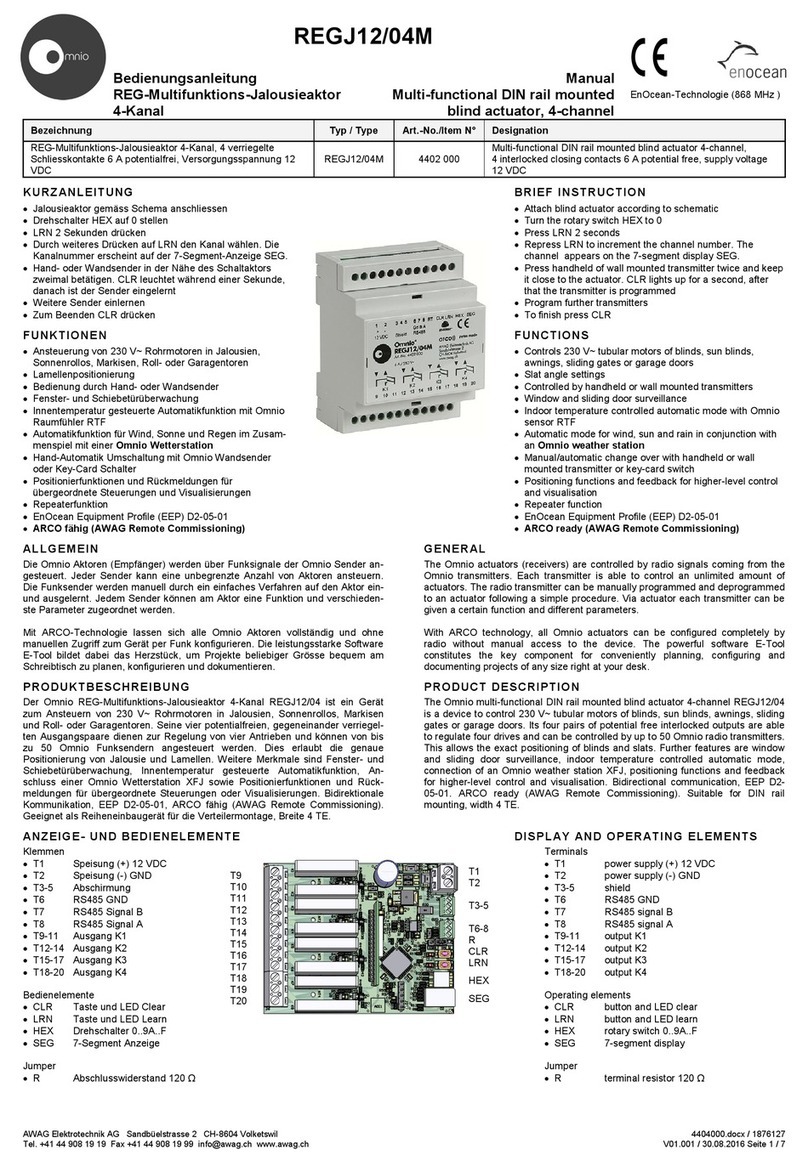
Omnio REGJ12/04M User manual

Omnio

Omnio REGJ12/04M User manual

Omnio UPS230/08 User manual

Omnio

Omnio UPS230/08 User manual

Omnio RATIO UPJ230/01 User manual

Omnio

Omnio RATIO UPJ230/01 User manual

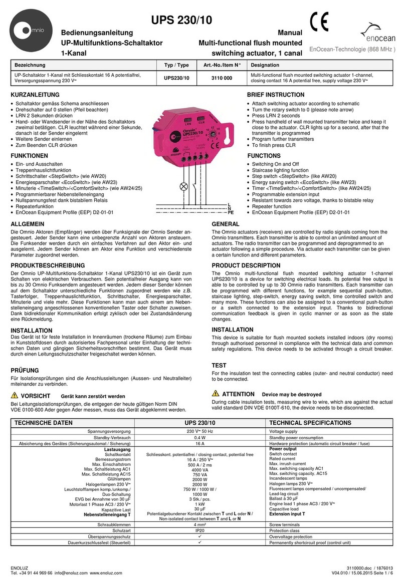
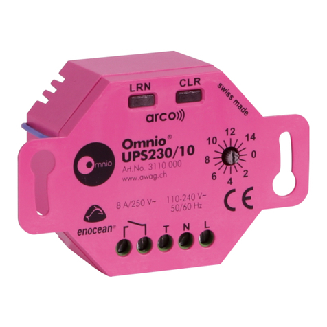
Omnio UPS230/10 User manual

Omnio

Omnio UPS230/10 User manual

Omnio TST230/10 User manual

Omnio

Omnio TST230/10 User manual

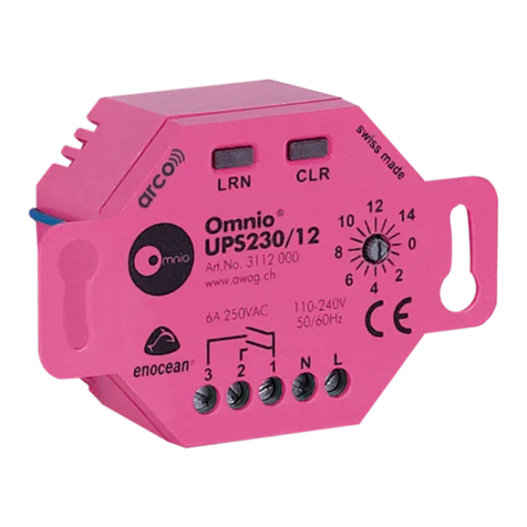
Omnio UPS230/12 User manual

Omnio

Omnio UPS230/12 User manual

Omnio UPS230/08 User manual

Omnio

Omnio UPS230/08 User manual

Omnio UPS230/10 User manual

Omnio

Omnio UPS230/10 User manual

Omnio UPS230/12 User manual

Omnio

Omnio UPS230/12 User manual

Omnio UPJ230/12 User manual

Omnio

Omnio UPJ230/12 User manual

Omnio REGJ12/04M Reference guide

Omnio

Omnio REGJ12/04M Reference guide

Popular Controllers manuals by other brands

HighPoint RocketRAID 37 Series installation guide

HighPoint

HighPoint RocketRAID 37 Series installation guide

Arena Luci LC5003 user manual

Arena Luci

Arena Luci LC5003 user manual

Linear Technology Analog Devices LT8708-1 datasheet

Linear Technology

Linear Technology Analog Devices LT8708-1 datasheet

tecnoelettra TE808 VVF instruction manual

tecnoelettra

tecnoelettra TE808 VVF instruction manual

Field Controls 46294900 manual

Field Controls

Field Controls 46294900 manual

Extron electronics MLC 206 quick start guide

Extron electronics

Extron electronics MLC 206 quick start guide

DOREMIDI DUH-10 quick start guide

DOREMIDI

DOREMIDI DUH-10 quick start guide

Omron CJ - REFERENCE  10-2009 Reference manual

Omron

Omron CJ - REFERENCE 10-2009 Reference manual

Dontek AQUASMART 5 SV instruction manual

Dontek

Dontek AQUASMART 5 SV instruction manual

Ei Electronics Ei450 instruction manual

Ei Electronics

Ei Electronics Ei450 instruction manual

Sanyo Denki Sanmotion R 3E S instruction manual

Sanyo Denki

Sanyo Denki Sanmotion R 3E S instruction manual

Safe Fleet LMU Controller installation guide

Safe Fleet

Safe Fleet LMU Controller installation guide

Smartgen ALC700 SERIES user manual

Smartgen

Smartgen ALC700 SERIES user manual

Akse Electrex EXA 96 installation guide

Akse

Akse Electrex EXA 96 installation guide

PDK Red 4 quick start guide

PDK

PDK Red 4 quick start guide

Ruijie RG-WS6512 Installation and reference guide

Ruijie

Ruijie RG-WS6512 Installation and reference guide

ABB ACS 6000 Service and maintenance manual

ABB

ABB ACS 6000 Service and maintenance manual

Hitachi HIDIC EH-150 Applications manual

Hitachi

Hitachi HIDIC EH-150 Applications manual

manuals.online logo
manuals.online logoBrands
  • About & Mission
  • Contact us
  • Privacy Policy
  • Terms and Conditions

Copyright 2025 Manuals.Online. All Rights Reserved.