Johnson Controls IQ Lock-PGK User manual

IQ Lock-PGK Smart Lock
Installation and User Guide
D-309240


ContentsSafety information............................................................................................................................................ 5
Warnings.............................................................................................................................................5
Cleaning the IQ Lock-PGK.................................................................................................................5
Introduction.......................................................................................................................................................5
Compatible panels.............................................................................................................................6
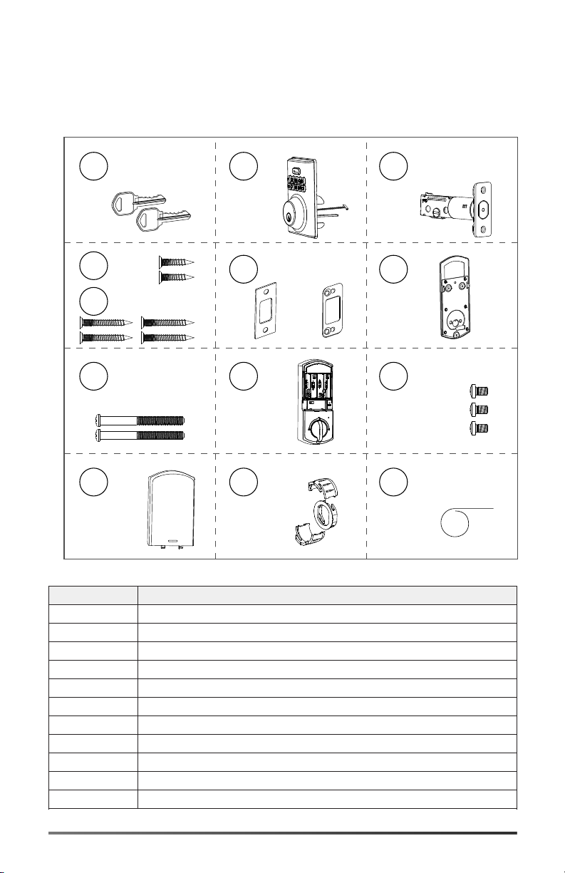
IQ Lock-PGK kit details..................................................................................................................................... 7
Specifications.....................................................................................................................................................8
Installing the IQ Lock-PGK............................................................................................................................... 9
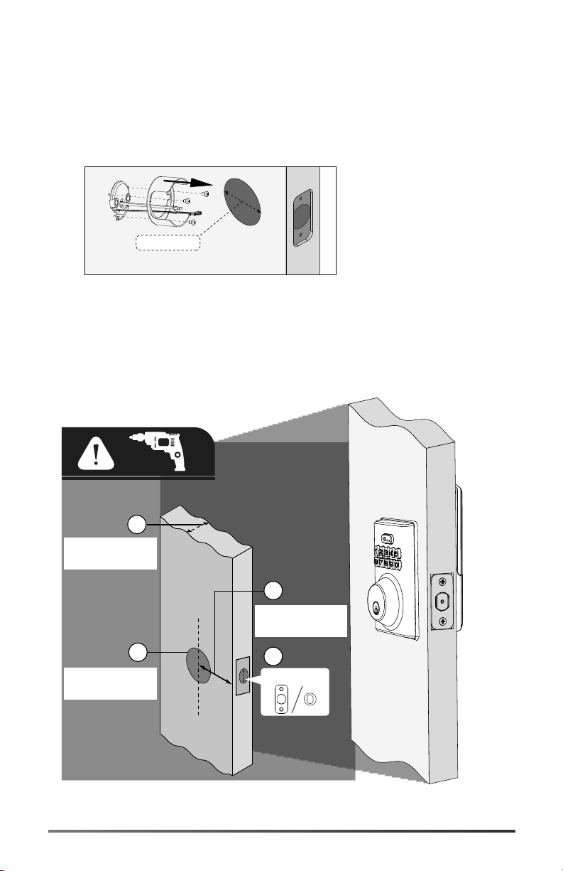
Prerequisites.....................................................................................................................................10
Choosing a faceplate.......................................................................................................................11
Checking the rectangular faceplate....................................................................................................... 11
Attaching the round drive-in collar.........................................................................................................12
Installing the latch........................................................................................................................... 14
Installing the exterior assembly.................................................................................................... 16
Installing the interior assembly..................................................................................................... 18
Setting left or right door orientation............................................................................................................20
Enrolling the IQ Lock-PGK with Auto Learn Enroll......................................................................................21
Enrolling the IQ Lock-PGK with Power G..................................................................................................... 21
Locking and unlocking the IQ Lock-PGK......................................................................................................22
IQ Lock-PGK notifications.............................................................................................................................. 22
Incorrect user code entry...............................................................................................................................22
Resetting the IQ Lock-PGK to factory default settings...............................................................................23
FCC Information..............................................................................................................................................23
Modification statement...................................................................................................................23
Interference statement...................................................................................................................23
Wireless notice................................................................................................................................. 23
ISED Statement............................................................................................................................................... 24
Warranty and EULA.........................................................................................................................................24
IQ Lock-PGK Installation and User Guide D-309240 3


Safety information
Read the safety information before you install the equipment. This equipment must be installed
only by a skilled person. A skilled person is an installer with appropriate technical training. The
installer must be aware of potential hazards during installation and measures available to minimize
risks to the installer and other people.
Warnings
• Protect your user codes.
• Restrict access to your lock and routinely check your settings to ensure they are not altered
without your knowledge.
• To make sure you are not locked out of your premises, monitor the IQ Lock-PGK battery
levels and replace them when required. Ensure you have access to the physical keys.
Cleaning the IQ Lock-PGK
To clean the IQ Lock-PGK, use a soft damp cloth.
WARNING: Do not use lacquer thinner, caustic soaps, abrasive cleaners, or polishes.
Introduction
The IQ Lock-PGK is a battery operated smart lock device that communicates with a compatible
IQ panel. The system is composed of the IQ Lock-PGK hardware, and the IQ panel. The IQ panel
monitors and reports the IQ Lock-PGK status.
Access the most recent online version of the IQ Lock-PGK installation and user guide at the
following link: https://bit.ly/3mnWCmx
Accédez à la version en ligne la plus récente du guide d'installation et d'utilisation IQ Lock-PGK au
lien suivant : https://bit.ly/3mnWCmx
Acceda a la versión en línea más reciente de la guía de usuario e instalación de IQ Lock-PGK en el
siguiente enlace: https://bit.ly/3mnWCmx
You can also scan the following QR code to access the most recent online version of the installation
and user guide.
Vous pouvez également scanner le code QR suivant pour accéder à la version en ligne la plus
récente du guide d'installation et d'utilisation.
También puede escanear el siguiente código QR para acceder a la versión en línea más reciente de
la guía de instalación y del usuario.
IQ Lock-PGK Installation and User Guide D-309240 5

Compatible panels
The IQ Lock-PGK is compatible with the following panels that use firmware version 4.4.0 and above:
• IQ Panel 4
• IQ 4 Hub
6 IQ Lock-PGK Installation and User Guide D-309240

IQ Lock-PGK kit details
Before you install the IQ Lock-PGK, ensure the kit contains the following items:
Figure 1: IQ Lock-PGK kit
A
B
C
H
I
J
K
L
M
D
F
G
E
Callout Component
A Backup key X 2
B Exterior assembly
C Latch
D Latch screws
E Strike screws
F Strike and optional reinforcement plate
G Mounting plate
H Screws 35 mm < door thickness < 58 mm
I Interior assembly
J Firecup screws
K Battery cover
IQ Lock-PGK Installation and User Guide D-309240 7

Callout Component
L Drive-in collar
M Reset tool
Note: The kit also contains four AA alkaline batteries.
Note: To install the IQ Lock-PGK you need a Philips head screwdriver, a flat head screwdriver,
and a hammer.
Specifications
The following table outlines the IQ Lock-PGK technical and mechanical specifications.
Table 1: Specifications
Type Description
Weight 1.6 kg / 3.6 lb
Operating temperature Exterior: -31ºF to 150ºF (-35ºC to 65ºC) Interior:
32ºF to 140ºF (0ºC to 60ºC)
Operating humidity 20% to 95%.
Operating voltage 4.6 V to 6.0 V
Battery life > 12 months, six user code unlock events, and
ten unlocking and locking cycles for each day
Frequency band 912 MHz to 919 MHz
Wireless communication protocol PowerG
8 IQ Lock-PGK Installation and User Guide D-309240

Installing the IQ Lock-PGK
The diagram shows you how to install the IQ Lock-PGK components.
Figure 2: IQ Lock-PGK installation overview
A
B
H
I
J
K
D
F
G
E
C
Callout Component
A Backup key
B Exterior assembly
C Latch
D Latch screws
E Strike screws
F Strike and optional reinforcement plate
G Mounting plate
H Screws 35 mm < door thickness < 58 mm
I Interior assembly
J Firecup screws
K Battery cover
IQ Lock-PGK Installation and User Guide D-309240 9

Prerequisites
Before you install the IQ Lock-PGK, ensure the following requirements are met:
• Measure the door hole to confirm that it is 1 1/2 in. or 2 1/8 in. (38 mm or 54 mm). If the hole
measures 1 1/2 in. (38 mm), remove the fire cup.
Figure 3: Exterior assembly hole dimension and removing the fire cup
1 1/2 in.
(38 mm)
• Measure to confirm that the door thickness is between 1 3/8 in. and 2 1/4 in. (35 mm to 58
mm).
• Measure to confirm that the door hole backset is 2 3/8 in. or 2 3/4 in. (60 mm or 70 mm).
• Measure to confirm that the latch hole is 1 in. (25.4 mm) from top to bottom.
Figure 4: Prerequisite check list
1 in. (25.4 mm)
A
1 1/2 in. or 2 1/8 in.
(38 mm or 54mm)
1 3/8 in. and 2 1/4 in.
(35 mm to 58 mm)
2 3/8 in. or 2 3/4 in.
(60 mm or 70 mm)
C
B
D
10 IQ Lock-PGK Installation and User Guide D-309240

Callout Component
A Door hole is 1 1/2 in. or 2 1/8 in. (38 mm or 54mm)
B Door thickness is between 1 3/8 in. and 2 1/4 in. (35 mm to 58 mm)
C Door hole backset is 2 3/8 in. or 2 3/4 in. (60 mm or 70 mm)
D Latch hole is 1 in. (25.4 mm) from top to bottom
Choosing a faceplate
The IQ Lock-PGK latch has a rectangular faceplate in place as the default faceplate. A round
faceplate or drive-in collar is included in the kit if it is required. The Checking the rectangular
faceplate and Attaching the round drive-in collar topics outline how to choose the correct faceplate
for your door.
Checking the rectangular faceplate
1. Check the door latch hole to see if the rectangular faceplate is suitable.
2. If the rectangular faceplate is suitable, continue to Installing the latch.
Figure 5: Rectangular faceplate
IQ Lock-PGK Installation and User Guide D-309240 11

Attaching the round drive-in collar
1. Check the door latch hole to see if a round faceplate is required.
Figure 6: Round faceplate
2. If a round faceplate is required, remove the rectangular faceplate from the latch with a flat
head screwdriver wedged between the faceplate and the faceplate clip.
Figure 7: Removing the rectangular faceplate
3. Remove the rectangular faceplate. Rotate it counterclockwise and pull.
Figure 8: Rotated rectangular faceplate
12 IQ Lock-PGK Installation and User Guide D-309240

4. Attach the drive-in collar.
Figure 9: Drive-in collar
IQ Lock-PGK Installation and User Guide D-309240 13

Installing the latch
Use the following steps to install the latch on the door.
Before you begin: Make sure the latch is in an unlocked position.
1. Hold the latch in front of the door hole, with the latch face flush against the door edge.
a. If the slotted hole is centered in the door hole, no adjustment is required. Proceed to
the next step.
b. If the slotted hole is not centered in the door hole, you need to make adjustments.
14 IQ Lock-PGK Installation and User Guide D-309240

c. Rotate and pull the latch to extend the latch. Adjust so that the slotted hole is centered.
2. Install the latch and use a Philips head screwdriver to secure the latch with two latch
screws.
IQ Lock-PGK Installation and User Guide D-309240 15

Installing the exterior assembly
Use the following steps to install the exterior assembly.
Before you begin: Make sure the bolt is in an unlocked position.
1. Route the cable below the latch.
2. Insert the torque blade into the slotted hole on the latch.
3. Route the cable through the hole in the mounting plate.
16 IQ Lock-PGK Installation and User Guide D-309240

4. Secure the mounting plate with two screws.
IQ Lock-PGK Installation and User Guide D-309240 17

Installing the interior assembly
Use the following steps to install the interior assembly. Do not load the batteries until the lock is
completely installed.
1. Remove the battery cover. Connect the cable and ensure it is connected tightly.
If you want to remove the cable, press the top of the white connector and pull the cable out
carefully.
PCB Connector
Cable Connector
2. Rotate the thumb turn to the vertical unlocked position.
Torque Blade
3. Test the lock by rotating the thumb turn to make sure the bolt can extend and retract
smoothly.
18 IQ Lock-PGK Installation and User Guide D-309240

IQ Lock-PGK Installation and User Guide D-309240 19

Setting left or right door orientation
Complete the following steps to ensure the lock functions correctly after you install it.
Before you begin: Ensure the hole in the door frame is drilled to a minimum of 1 in. / 25 mm
deep.
1. With the thumb turn in the vertical unlocked position, insert 4 AA batteries.
2. If the latch bolt does not start as part of auto-orientation, use a sharp pointed tool to press
and hold the reset button for 5 seconds until you hear a long beeping sound.
3. If the reset is successful, the latch bolt extends.
4. Replace the battery cover.
5. Install the strike on the door frame.
20 IQ Lock-PGK Installation and User Guide D-309240
Table of contents
Popular Door Lock manuals by other brands

Samsung SDS
Samsung SDS SHS-H705 user manual

ANXELL
ANXELL AXM-800ML Series Installation instruction

BQT Solutions
BQT Solutions COBALT-mini YD39M Installation and operating instructions

Abus
Abus PR2600 Fitting and operating instructions

XPR Access
XPR Access HL1000-MF Installer manual

Masterlock
Masterlock BCCO0615 Instructions for installation