Johnson 40-6004 User manual

©2013 Johnson Level & Tool - Rev. 1 1
Laser Distance Measure
Model No. 40-6004
Instruction Manual
Congrat lations on yo r choice of this Laser Distance Meas re. We
s ggest yo read this instr ction man al thoro ghly before sing the
instr ment. Save this instr ction man al for f t re se.
This is a Class II laser tool and is manufactured to comply with CRF 21,
parts 1040.10 and 1040.11 as well as international safety rule IEC 285.
The laser also complies with EMC Test according to EN61000-6-3;
2001+A11:2004, EN 6100-6-1:2011, EN 6100-4-2, EN 61000-4-3, EN
60825, FCC Test according to PART 15.
6833H-E glish_Ma uals 4/2/13 1:26 PM Page 1

2©2013 Johnson Level & Tool - Rev. 1
Table of Contents
1.Kit Contents . . . . . . . . . pg. 2
2.Safety Information . . . pg. 2-3
3.Location/Content of
Warning Labels . . . . . . . pg. 3
4.Location of Parts/
Components . . . . . . . pg. 4-5
5.Start Up - Battery Installation
Instructions . . . . . . . . . . pg. 7
6.Using the Product . . pg. 8-21
7.
Technical Specifications
pg. 22
8.Product Warranty. . . . . pg. 23
9.Product Registration . . pg. 24
1. Kit Contents
Description for Model 40-6004 Qty.
Laser Distance Measure
1
“AA” Alkaline Batteries 2
Instruction Manual 1
2. Safety Instructions
Please read and understand all of the following instructions, prior
to using this tool. Failure to do so, may result in bodily injury.
CAUTION!
Class II Laser Product
Max. Power Output: ≤1mW
Wavelength: 640-660nm
THIS TOOL EMITS LASER RADIATION.
DO NOT STARE INTO BEAM.
AVOID DIRECT EYE EX OSURE.
6833H-E glish_Ma uals 4/2/13 1:26 PM Page 2

©2013 Johnson Level & Tool - Rev. 1 3
ATTENTION IMPORTANT
• Read all instructions prior to operating this laser tool. Do not remove any labels from tool.
• Do not stare directly at the laser beam.
• Do not project the laser beam directly into the eyes of others.
• Do not set up laser tool at eye level or operate the tool near a reflective surface as
the laser beam could be projected into your eyes or into the eyes of others.
• Do not place the laser tool in a manner that may cause someone to unintentionally
stare into the laser beam. Serious eye injury may result.
• Do not operate the tool in explosive environments, i.e. in the presence of gases or
flammable liquids.
• Keep the laser tool out of the reach of children and other untrained persons.
• Do not attempt to view the laser beam through optical tools such as telescopes as
serious eye injury may result.
• Always turn the laser tool off when not in use or left unattended for a period of time.
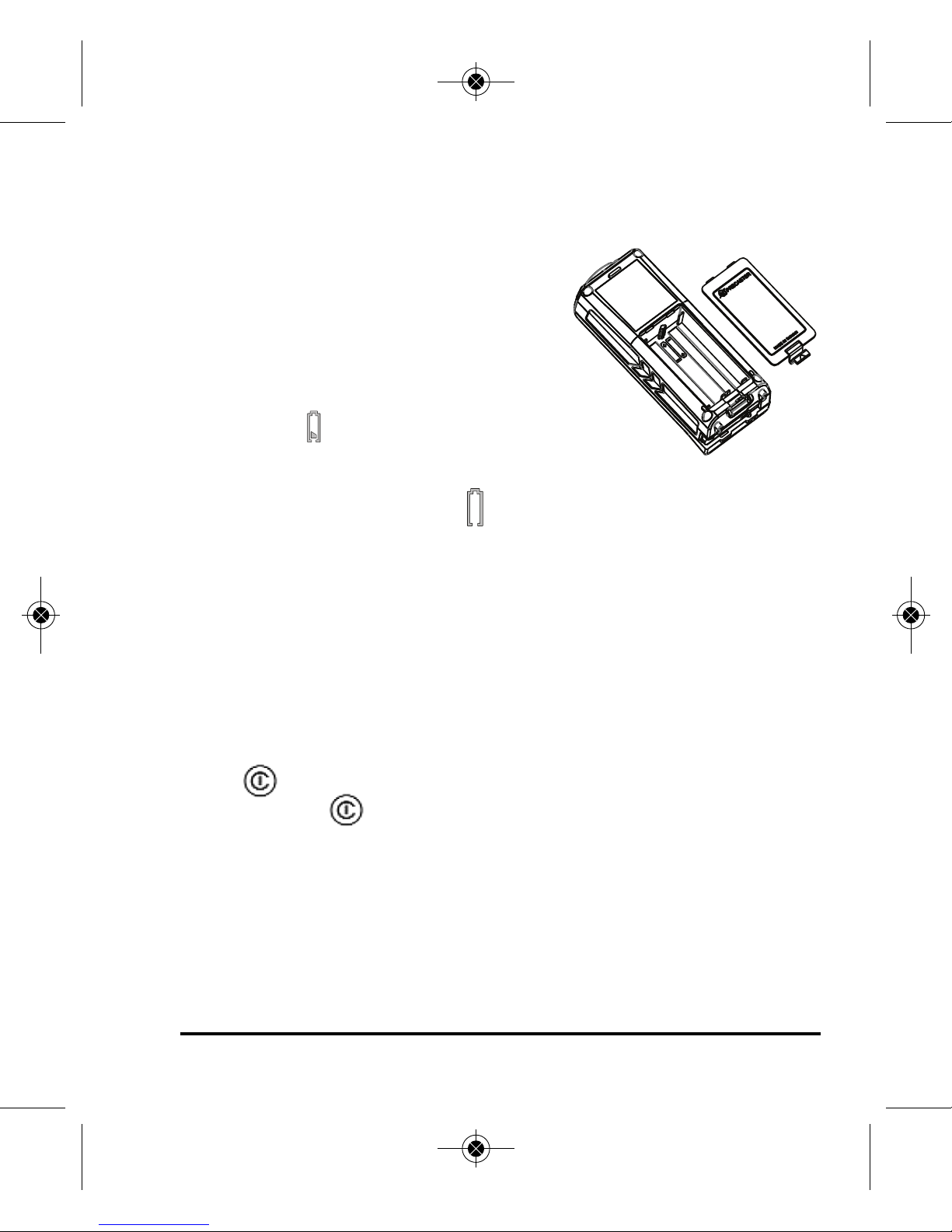
• Remove the battery when storing the tool for an extended time (more than 3 months) to
avoid damage to the tool should the batteries deteriorate.
• Do not attempt to repair or disassemble the laser tool. If unqualified persons attempt
to repair this tool, warranty will be void.
• Use only original ohnson
®
parts and accessories purchased from your ohnson
®
authorized dealer.
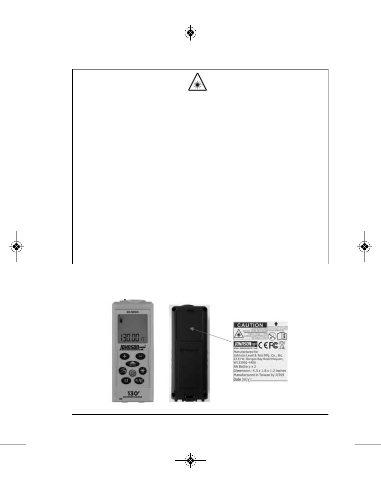
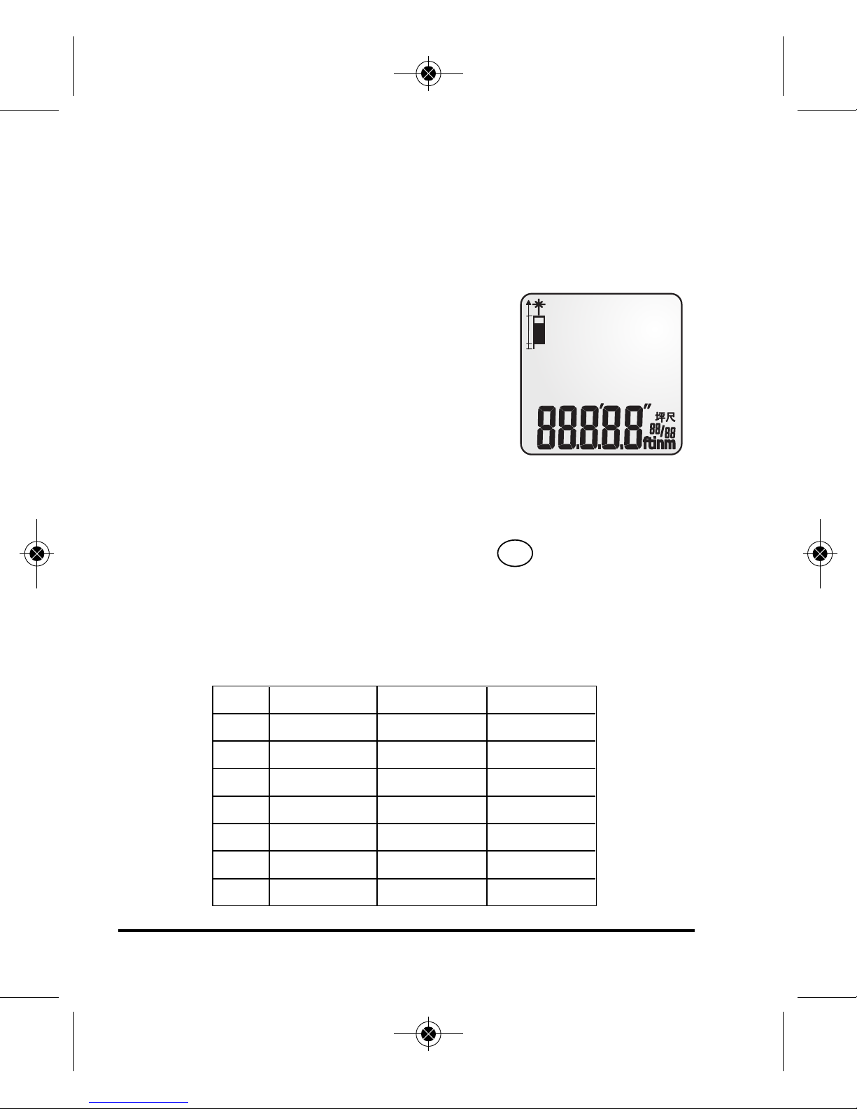
3. Location/Content of Warning Labels
6833H-E glish_Ma uals 4/2/13 1:26 PM Page 3

4©2013 Johnson Level & Tool - Rev. 1
4. Location of art/Components
1
28
9
10
11
13
14
12
3
4
5
6
7
1. LCD Display
2. Add
3. Measure Button
4. Measure Function
Area
Volume
Pythagoras
5. Unit of Measure
6. Wrist Strap Bracket
7. Laser Emitting Window
8. Subtract
9. Backlight
10. Power Button/Clear/Escape
11. Measuring Reference Position/
Continuous Laser Mode
12. Receiver Window
13. Battery Cover
14. Corner Measurement
Extension Piece
1
28
9
10
11 13
14
3
4
5
6
7 12
6833H-E glish_Ma uals 4/2/13 1:26 PM Page 4

©2013 Johnson Level & Tool - Rev. 1 5
1. Active Laser Indicator
2. Indirect Measuring
Single Pythagoras
3. Measuring Function
Area Measuring
Volume Measuring
4. Measurement Reference Position
5. Add and Subtract
6. Maximum Display
7. Minimum Display
8. Main Screen and Units of Measure
9. Battery Status
10. Sub-Screen and Units
of Measure
6833H-E glish_Ma uals 4/2/13 1:26 PM Page 5

6©2013 Johnson Level & Tool - Rev. 1
Measuring Reference
Range
Range is specified between a minimum 2-inches to a maximum of
130-feet with an accuracy of 1/16”. Longer ranges will be found by the
instrument but a variance in the accuracy may exist. At night or dusk
the range may be greater than during daylight or if the target has poor
reflective properties.
Target Surfaces
Measuring errors may occur when aiming at surfaces composed
of colorless liquids (e.g. water), glass, Styrofoam or similar semi-
permeable surfaces. Aiming at high gloss surfaces may deflect the
laser beam and lead to measurement errors.
Hazards of Use
Be aware that errors in distance measurements may occur if the
instrument is defective or has been dropped, been misused or
modified.
Note
Conduct periodic test measurements to ensure the instrument is
measuring accurately and consistently. This is most important if the
instrument has been exposed to abnormal use. Always confirm
accuracy before and during important measurements. Keep the laser
distance measure optic clean and inspect for damage.
6833H-E glish_Ma uals 4/2/13 1:26 PM Page 6

©2013 Johnson Level & Tool - Rev. 1 7
5. Start Up - Battery Installation
1. Remove battery compartment lid.
2. Insert 2-“AA” batteries observing
correct polarity.
3. Close battery compartment lid.
4. Battery status will be shown in start
up screen.
5. When the icon appears there are
approximately 1,000 measurements
remaining.
6. Replace batteries when the icon flashes on the screen.
7. Remove old batteries and replace with new “AA” alkaline batteries
following steps 1-3 above.
Note
Use only alkaline batteries. If the instrument will not be used for an
extended time, remove the batteries to protect against corrosion.
ower Button
Press Power Button to power up.
Press and hold Power Button to power off.
Automatic Shutoff
Laser will turn off after 30 seconds
Unit will turn off after 3 minutes of inactivity
6833H-E glish_Ma uals 4/2/13 1:26 PM Page 7

8©2013 Johnson Level & Tool - Rev. 1
6. Using the roduct
Tip: lace a white sheet of paper over the targeted measuring
surface if error message Err02 occurs to improve the return signal.
Measuring
Measuring Modes
Your Laser Distance Measure has four
measuring modes:
Length
Area/Square
Volume/Cube
Indirect/Pythagoras
Units of Measure
This instrument has seven units of measure. The desired unit of
measure can be set by pressing and releasing . The main screen
will display square feet/square meters or cubic feet/cubic meters in a
decimal format when calculating area and volume.
The following units can be set:
U
Distance Area Vo ume
1. 0.000 m 0.000 m20.000 m3
2. 0.00 ft 0.00 ft20.00 ft3
3.
0’0” 1/32 0.00 ft20.00 ft3
4. 0.00 in 0.00 ft20.00 ft3
5. 0 1/32 in 0.00 ft20.00 ft3
6. 0 1/16 in 0.00 ft20.00 ft3
7. 0 1/8 in 0.00 ft20.00 ft3
6833H-E glish_Ma uals 4/2/13 1:26 PM Page 8

©2013 Johnson Level & Tool - Rev. 1 9
Measurement Reference osition
Be sure to adjust the measuring reference position prior to engaging a
measuring calculation mode. Press and release to scroll through
the reference point options
Front
Rear
Corner Extension Piece
Single Distance Measuring
Press to turn power on.
Direct Laser Beam to Target.
Press and release .
Keep unit still until measurement has been
recorded. Laser beam will shut off once
measurement has been recorded.
Press and release to clear screen.
Press and hold to power down unit.
6833H-E glish_Ma uals 4/2/13 1:26 PM Page 9

10 ©2013 Johnson Level & Tool - Rev. 1
Adding or Subtracting
Press and release the button to activate laser.
Press and release the button to record first measurement.
Press and release (first measurement moves to sub value position
on screen and a “+” sign temporarily appears).
Press and release the button to activate laser. (If inactive.)
Press and release the button to record second measurement.
Press and release to add measurement 1 (stored in sub value
position) and measurement 2 together.
To add another measurement to sum (repeat same measurement
sequence) to tally.
To subtract a value in the tally sequence press button.
+
+
-
This laser distance measure has the capability to add or subtract area,
volume or indirect measurement calculations. For example, if you need
the square footage of four rooms this instrument will allow you to add
each area calculation together to sum the dimensions of the four
6833H-E glish_Ma uals 4/2/13 1:26 PM Page 10

©2013 Johnson Level & Tool - Rev. 1 11
Continuous Measuring
This mode will take continuous
measurements as you move closer or
further away from the target.
Minimum working range is 2-inches.
Maximum working range is 130-feet.
Press and hold the button to activate continuous
measuring mode.
To pause Continuous Measuring mode press or .
To resume Continuous Measuring mode press or to exit
Continuous Measuring mode press .
Minimum / Maximum Measurements
As the laser beam is scanned across
the measuring surface, the
maximum and minimum distance is
simultaneously recorded in the sub
value positions on the screen as the
laser is scanning the targeted surface.
rooms. The same holds true for volume or indirect measurement
modes. Please see each respective measurement section for the
step-by-step instructions.
6833H-E glish_Ma uals 4/2/13 1:26 PM Page 11

12 ©2013 Johnson Level & Tool - Rev. 1
Area Measurement (Square2)
Press Power Button to turn power on.
Press button to enter Area mode.
A rectangle icon will appear on the upper left side of screen.
Observe flashing line for each required measurement (Length & Width).
Follow flashing line instructions on screen to measure width & length.
Press and release button to record measurements.
Area calculation will be presented in sub value position at top of screen.
Note: Unit of measure for area calculation will be displayed in decimal
form in square feet or square meters on main screen.
To tally (or sum) the Area calculations of multiple rooms use the
following steps:
Suggestions:
Be sure you have the desired unit of measure selected.
For better visibility press and hold the backlight button to
activate the backlight.
6833H-E glish_Ma uals 4/2/13 1:26 PM Page 12

©2013 Johnson Level & Tool - Rev. 1 13
It is recommended that yo test this f nction prior to taking important
meas rements. Simply write down each Area calc lation on a piece of
paper and add (or s btract) the Area calc lations along with the Laser
Distance Meas re. This will familiarize yo with the process of how the
calc lations are determined.
Follow the Area measurement instructions above to enter Area mode.
Once the first Area calculation is taken it will be displayed in the bottom
row on the LCD screen.
Press and release the button.
Upon pressing the button the LCD screen will be cleared however the
Area calculation is stored.
The Area mode will remain active on the LCD screen.
Take the second room Area dimensions.
When the Area calculation appears in the bottom row press and release
the button again.
You will now see the previous Area calculation at the top row being added
to the most recent Area calculation in the middle row.
The sum of both Area calculations will be displayed in the bottom row.
Follow this sequence to continue tallying additional room dimensions.
To subtract an Area measurement simply press and release the
button during the sequence and that value will be deducted from the total.
6833H-E glish_Ma uals 4/2/13 1:26 PM Page 13

14 ©2013 Johnson Level & Tool - Rev. 1
Volume Measurement (Cube3)
Press Power Button to turn power on.
Press and release button two times.
A 3- dimensional rectangle icon will appear on the upper left side of
screen. Observe flashing line for each required measurement (Length,
Height & Width).
Follow flashing line instructions on screen to measure length, width &
height. Press and release button to record measurements.
Volume calculation will be presented in sub value position at top of
screen.
Note: Unit of measure for cube calculation will be displayed in decimal
form in cubic feet or cubic meters on main screen.
To tally (or sum) the Volume calculations of multiple rooms use
the following steps:
Suggestions:
Be sure you have the desired unit of measure selected.
6833H-E glish_Ma uals 4/2/13 1:26 PM Page 14

©2013 Johnson Level & Tool - Rev. 1 15
For better visibility press and hold the backlight button to
activate the backlight.
It is recommended that yo test this f nction prior to taking important
meas rements. Simple write down each Vol me calc lation on a piece
of paper and add (or s btract) the Vol me calc lations along with the
Laser Distance Meas re. This will familiarize yo with the process of
how the calc lations are determined.
Follow the Volume measurement instructions above to enter Volume mode.
Once the first Volume calculation is taken it will be displayed in the bottom
row on the LCD screen.
Press and release the button.
Upon pressing the button the LCD screen will be cleared however the
Volume calculation is stored.
The Volume mode will remain active on the LCD screen.
Take the second Volume dimensions.
When the Volume calculation appears in the bottom row press and
release the button again.
You will now see the previous Volume calculation at the top row being
added to the most recent Volume calculation in the middle row.
The sum of both Volume calculations will be displayed in the bottom row.
Follow this sequence to continue tallying additional room dimensions.
To subtract an Volume measurement simply press and release the
button during the sequence and that value will be deducted from the total.
6833H-E glish_Ma uals 4/2/13 1:26 PM Page 15

16 ©2013 Johnson Level & Tool - Rev. 1
Indirect Measurements ( ythagorean Methods)
All Calculations are based on Pythagorean Theorem a2+b2=c2.
This function allows for the measurement of hard to reach jobs.
Follow the order of the flashing lines for each required measurement.
Note: For accurate measurements the instrument’s position must be
held constant. For example, note the position of your hand when
taking first measurement. Do not move your hand when preparing to
take the second measurement. Simply pivot your wrist (keeping
instrument in same position) to align the next target. Then record
next measurement.
Calculates dista ce betwee
Poi t 1 a d Poi t 2
6833H-E glish_Ma uals 4/2/13 1:26 PM Page 16

©2013 Johnson Level & Tool - Rev. 1 17
Indirect Measurement 1 (2 shot measurements FULL Height)
Press and release button three times to enter Indirect Measuring Mode.
Position instrument by observing flashing line on screen. (Base of triangle)
Press and release Measure button to record first measurement.
Hold instrument position and pivot to aim laser at second target
observing flashing line on screen.
Press and release Measure button to record second measurement.
Pythagoras calculation (full height) will be presented in main screen
position at bottom.
To tally (or sum) the Indirect measurement calculations of
multiple rooms use the following steps:
Suggestions:
Be sure you have the desired unit of measure selected.
For better visibility press and hold the backlight button to
activate the backlight.
It is recommended that yo test this f nction prior to taking important
meas rements. Simple write down each Indirect meas rement calc lation
on a piece of paper and add (or s btract) the Indirect meas rement
calc lations along with the Laser Distance Meas re. This will familiarize
yo with the process of how the calc lations are determined.
Follow the Indirect measurement instructions above to enter Indirect
measurement mode.
Once the first Indirect measurement calculation is taken it will be
displayed in the bottom row on the LCD screen.
6833H-E glish_Ma uals 4/2/13 1:26 PM Page 17

Press and release the button.
Upon pressing the button the LCD screen will be cleared however the
Indirect measurement calculation is stored.
The Indirect measurement mode will remain active on the LCD screen .
Take the second Indirect measurement.
When the Indirect measurement calculation appears in the bottom row
press and release the button again.
You will now see the previous Indirect measurement calculation at the top
row being added to the most recent Indirect measurement calculation in
the middle row.
The sum of both Indirect measurement calculations will be displayed in
the bottom row.
Follow this sequence to continue tallying additional Indirect measurement
dimensions.
To subtract an Indirect measurement simply press and release the
button during the sequence and that value will be deducted from the total.
18 ©2013 Johnson Level & Tool - Rev. 1
6833H-E glish_Ma uals 4/2/13 1:26 PM Page 18

©2013 Johnson Level & Tool - Rev. 1 19
Backlight
Press and release the button to activate
backlight. Repeat this step to turn off backlight.
Indoor & Outdoor Measurements
This model is designed to take measurements indoors under normal
settings. The measuring surfaces and ambient light are critical factors
to the quality of measurement (indoors an outdoors). Outdoor
measurement capability may be limited due to sunlight/UV ray
interference. Please note that in some situations the unit may have
difficulty reading the surface you try to measure if lighting or sunlight
is intense and/or the surface being measured does not reflect the
laser beam appropriately.
6833H-E glish_Ma uals 4/2/13 1:26 PM Page 19

20 ©2013 Johnson Level & Tool - Rev. 1
Error Codes
Code Description Solution
Err01
Distance is outside of measuring range
Measure in a shorter
distance or longer distance
Err02 Reflected signal is too weak Measure a better surface
Err03 Out of display range Maximum Value: 99,999
Split up measurement area
into smaller segments.
Err04
Pythagorean theorem calculation error
Check and verify value or the
sequence of measurements
is correct
Err05 Low Battery Install a new battery
Err06
Temperature is outside of working range
Measure in an environment
within
specified working
temperature range
Err07 Ambient light is too strong Measure in a darker place
(shadow target)
Measurement Errors
Error messages will appear if the unit’s receiver is not getting a
sufficient laser return signal.
Common surfaces that could cause an error reading:
- Water or other fluids
- Translucent to clear surfaces like glass or acrylic
- Porous or dark surfaces may require longer reading times or
cause an error reading
- Moving surfaces or objects such as curtains
- Highly reflective or angled surfaces may deflect the laser
beam signal
6833H-E glish_Ma uals 4/2/13 1:26 PM Page 20
Table of contents
Popular Analytical Instrument manuals by other brands

AMES
AMES 64623 Owner's manual & safety instructions

A&D
A&D LCB05 Series instruction manual

Bante Instruments
Bante Instruments D0scan10 instruction manual

Whistler
Whistler WIC5100 owner's manual

PCE Health and Fitness
PCE Health and Fitness PCE-VE 700 Instructions for use

Hach
Hach Polymetron 9526 Basic user manual