joke ENESKAsonic User manual

Operating
instructions
ENESKAsonic


33
Table of contents
1 Notes about these instructions . . . . . . . . . . . . . . . . . . . . . . . . . . . . . . . . . . . . . . . . 4
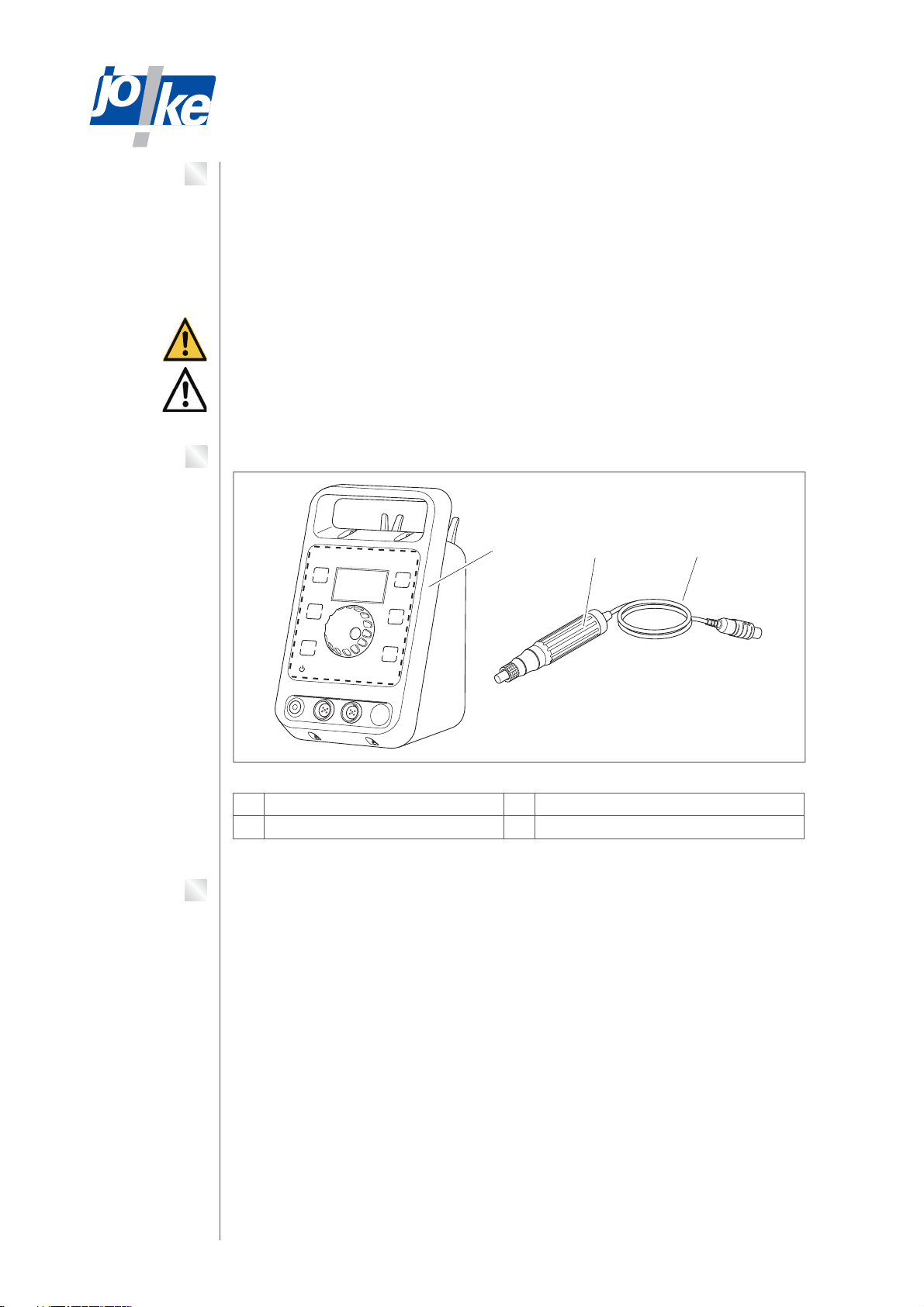
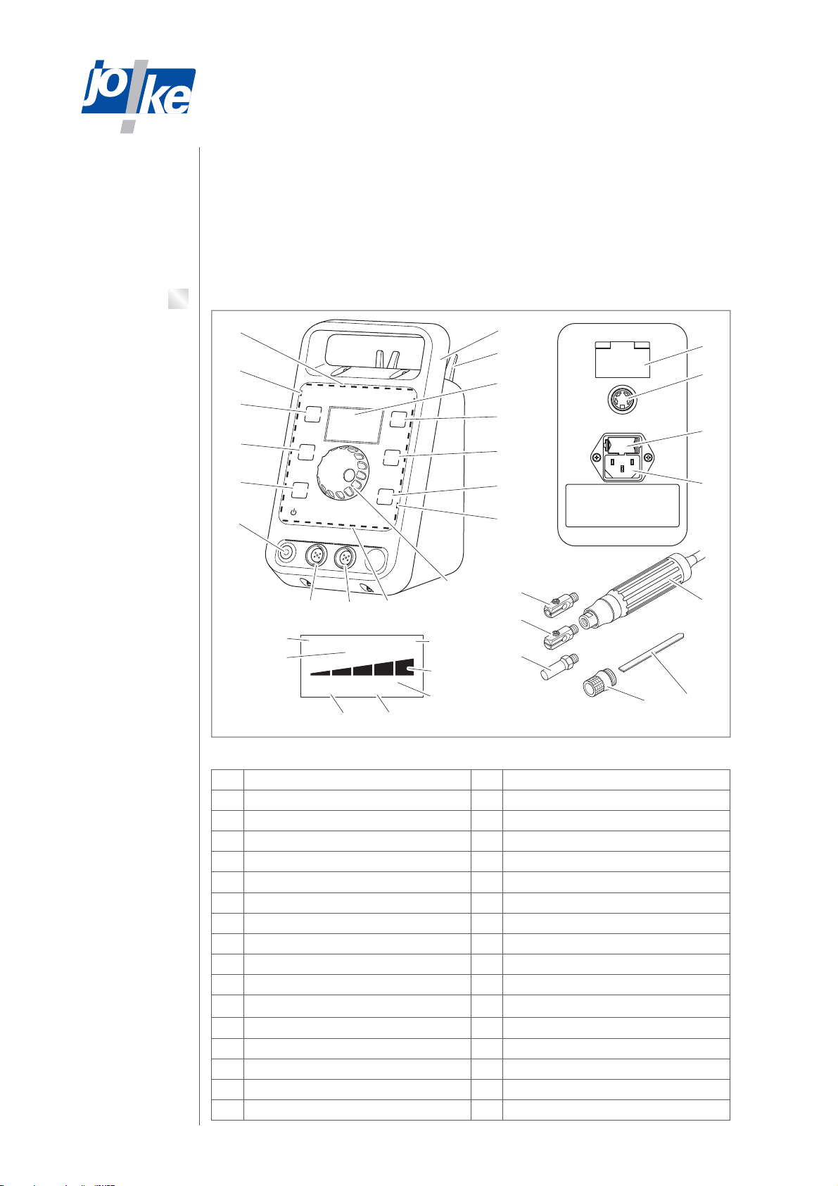
2 Product overview . . . . . . . . . . . . . . . . . . . . . . . . . . . . . . . . . . . . . . . . . . . . . . . . . . . . 4
3 Parts supplied for an ENESKAsonic ultrasonic system. . . . . . . . . . . . . . . . . . . . 4
4 Technical data for ENESKAsonic control unit. . . . . . . . . . . . . . . . . . . . . . . . . . . . 5
5 Safety. . . . . . . . . . . . . . . . . . . . . . . . . . . . . . . . . . . . . . . . . . . . . . . . . . . . . . . . . . . . . . . 5
Intended use . . . . . . . . . . . . . . . . . . . . . . . . . . . . . . . . . . . . . . . . . . . . . . . . . . . . . . . . . . . . . . . . . . . . . . 5
General safety instructions. . . . . . . . . . . . . . . . . . . . . . . . . . . . . . . . . . . . . . . . . . . . . . . . . . . . . . . . . . 5
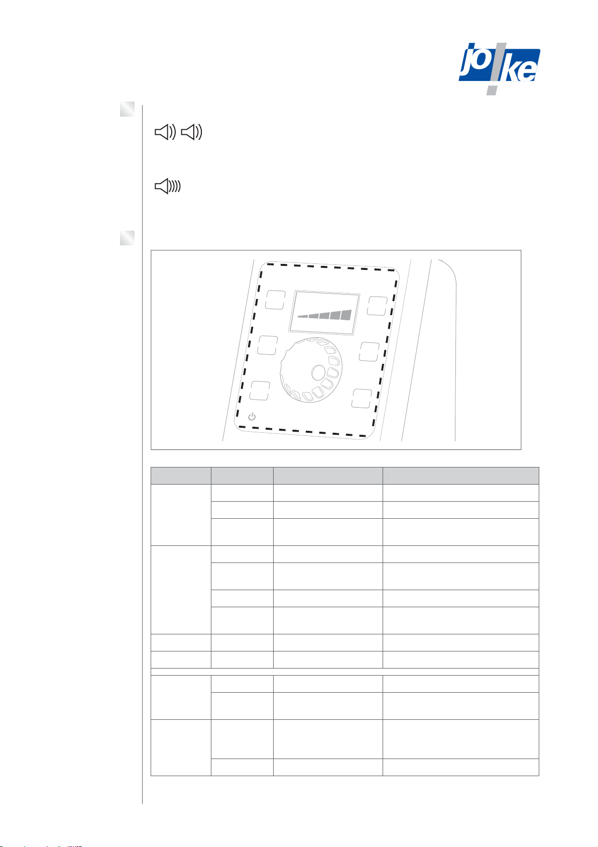
6 Controls and indicators . . . . . . . . . . . . . . . . . . . . . . . . . . . . . . . . . . . . . . . . . . . . . . . 6
7 The function of the signal sounds . . . . . . . . . . . . . . . . . . . . . . . . . . . . . . . . . . . . . . 7
8 Functions of the LED display strips . . . . . . . . . . . . . . . . . . . . . . . . . . . . . . . . . . . . . 7
9 Function of the ventilation. . . . . . . . . . . . . . . . . . . . . . . . . . . . . . . . . . . . . . . . . . . . . 8
10 Calling up the menu and navigating . . . . . . . . . . . . . . . . . . . . . . . . . . . . . . . . . . . . 8
11 Start up . . . . . . . . . . . . . . . . . . . . . . . . . . . . . . . . . . . . . . . . . . . . . . . . . . . . . . . . . . . . . 9
Replace the fuse (if necessary) . . . . . . . . . . . . . . . . . . . . . . . . . . . . . . . . . . . . . . . . . . . . . . . . . . . . . . 9
Connecting a handpiece . . . . . . . . . . . . . . . . . . . . . . . . . . . . . . . . . . . . . . . . . . . . . . . . . . . . . . . . . . . . 9
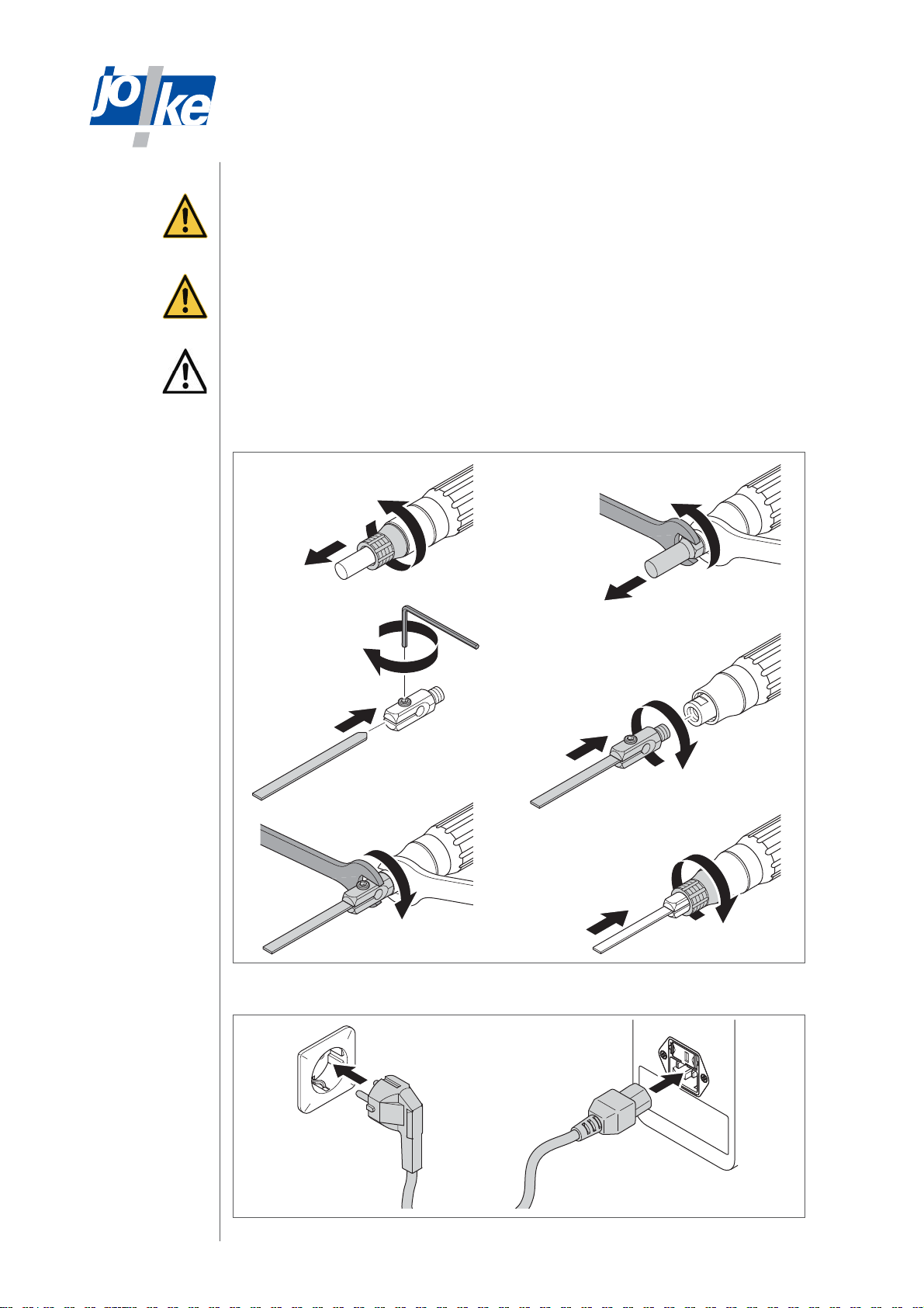
Mounting/changing the tool holder and tool . . . . . . . . . . . . . . . . . . . . . . . . . . . . . . . . . . . . . . . . . . 10
Connecting the mains cable . . . . . . . . . . . . . . . . . . . . . . . . . . . . . . . . . . . . . . . . . . . . . . . . . . . . . . . . 10
Switching the unit on . . . . . . . . . . . . . . . . . . . . . . . . . . . . . . . . . . . . . . . . . . . . . . . . . . . . . . . . . . . . . . 11
Setting the language (if necessary). . . . . . . . . . . . . . . . . . . . . . . . . . . . . . . . . . . . . . . . . . . . . . . . . . 11
12 Connecting the foot pedal (optional). . . . . . . . . . . . . . . . . . . . . . . . . . . . . . . . . . . 11
13 Operation . . . . . . . . . . . . . . . . . . . . . . . . . . . . . . . . . . . . . . . . . . . . . . . . . . . . . . . . . .12
Switching the unit on . . . . . . . . . . . . . . . . . . . . . . . . . . . . . . . . . . . . . . . . . . . . . . . . . . . . . . . . . . . . . . 12
Selecting a handpiece . . . . . . . . . . . . . . . . . . . . . . . . . . . . . . . . . . . . . . . . . . . . . . . . . . . . . . . . . . . . . 12
Switching the handpiece on . . . . . . . . . . . . . . . . . . . . . . . . . . . . . . . . . . . . . . . . . . . . . . . . . . . . . . . . 12
Choosing the power, BOOST function. . . . . . . . . . . . . . . . . . . . . . . . . . . . . . . . . . . . . . . . . . . . . . . . 13
Adjust the working point during operation (TUNE, if required). . . . . . . . . . . . . . . . . . . . . . . . . . . 13
Stopping the handpiece. . . . . . . . . . . . . . . . . . . . . . . . . . . . . . . . . . . . . . . . . . . . . . . . . . . . . . . . . . . . 14
Switch the unit o. . . . . . . . . . . . . . . . . . . . . . . . . . . . . . . . . . . . . . . . . . . . . . . . . . . . . . . . . . . . . . . . . 14
14 Testing the handpiece’s function . . . . . . . . . . . . . . . . . . . . . . . . . . . . . . . . . . . . . . 14
15 Setting the timer . . . . . . . . . . . . . . . . . . . . . . . . . . . . . . . . . . . . . . . . . . . . . . . . . . . . 15
16 Calling up information about the unit . . . . . . . . . . . . . . . . . . . . . . . . . . . . . . . . . . 15
17 Setting the signal tone and LEDs . . . . . . . . . . . . . . . . . . . . . . . . . . . . . . . . . . . . . . 16
18 USB interface . . . . . . . . . . . . . . . . . . . . . . . . . . . . . . . . . . . . . . . . . . . . . . . . . . . . . . 16
19 Firmware update . . . . . . . . . . . . . . . . . . . . . . . . . . . . . . . . . . . . . . . . . . . . . . . . . . . . 16
Doing a firmware update. . . . . . . . . . . . . . . . . . . . . . . . . . . . . . . . . . . . . . . . . . . . . . . . . . . . . . . . . . . 16
Possible errors during a firmware update . . . . . . . . . . . . . . . . . . . . . . . . . . . . . . . . . . . . . . . . . . . . 17
20 Maintenance, care and disposal . . . . . . . . . . . . . . . . . . . . . . . . . . . . . . . . . . . . . . 18
21 Troubleshooting and fixing faults . . . . . . . . . . . . . . . . . . . . . . . . . . . . . . . . . . . . . 18

44
Notes about these instructions
These operating instructions enable the operator to operate, care for and maintain the ENESKA-
sonic system correctly. These operating instructions are part of the system and must always be
kept at hand at the place of use. If the ENESKAsonic system is passed on to a third party then
these operating instructions must be passed on too.
Instructions which must be strictly observed to prevent hazards or damage are marked as fol-
lows:
Warning!
Warns of hazards that could result in serious injury or death.
Caution!
Warns of hazards that can lead to damage to objects.
For technical problems or other questions please contact our service department.
Product overview
C
B
A
TUNE
BOOST
MEM
A
B
C
2 31
Fig. 1
1 ENESKAsonic control unit 3 Handpiece cable
2 Ultrasonic handpiece
Parts supplied for an ENESKAsonic ultrasonic system
• 1 x ENESKAsonic ultrasonic system, control unit (order no. 0 012 001)
• 1 x ENESKAsonic ultrasonic system, handpiece JUS-45 PB-ES (order no. 0 012 003)
• 1 x ENESKAmicro handpiece rest standard, black (order no. 0 011 110)
• 1 x ENESKAsonic display guard, made of hardened glass (order no. 0 011 098-G)
• 1 x mains cable set for Germany, Switzerland, England and Europe (order no. 0 007 435-1)
• 2 x fuses 4A TR250V / 5 x 20mm (order no. 1 711 407-1) for 110V use
• 1 x Allen key (order no. 0 006 304)
• 2 x 10mm spanner (order no. 0 006 347)
• 1 x tool holder hole dia. 3mm, thread M6 x 0.9 (order no. 0 006 306-E)
• 1 x tool holder slit width 1mm, thread M6 x 0.9 (order no. 0 006 310-E)
• 1 x ENESKAsonic, starter set ceramic fibre file NEW Super Stone, 3 items in a box (order no.
0012007)
1
2
3

55
Technical data for ENESKAsonic control unit
Connections 2 connections for ultrasonic handpieces
Supply voltage 115 / 230V, 50 / 60Hz, 150VA
Power consumption max. 80W
Frequency range 20–40kHz
Power supply socket fuse 16A
Dimensions (W x H x D) 135 x 235 x 200mm
Weight 2.7kg
Ambient conditions 0°C to +40°C
10% to 85% humidity
Noise pressure level < 70dB (A)
Permissible handpieces
JUS-45 PB-ES; 50W, 22.5kHz (40 μm)
JUS-50 ES; 50W, 22.5kHz (40 μm)
Approved threaded connection for the
handpiece Thread M6/FINE (M6 x 0.9)
USB typeA interface Charging voltage 5V at 1.8A
The manufacturer's logo, type designation, CE mark and serial number are located on the back of
the control unit and on the housing of the handpiece.
A complete overview of accessories can be found in the JOKE catalogue for surface treatment,
in the "Drive systems and handpieces” chapter.
The list of spare parts and the declaration of conformity are available online at www.joke-tech-
nology.de .
Safety
Intended use
ENESKAsonic systems are designed exclusively for removing material, deburring, lapping and
polishing with a straight motion.
ENESKAsonic systems may only be used with approved components and accessories (see
chapter3, Technical specifications).
The values specified in the technical specifications of the individual components must not be
exceeded when working with the ENESKAsonic system.
ENESKAsonic control units may only be used as described in these operating instructions. Any
other use or use going beyond this is considered improper use. The manufacturer will not be
liable for damage resulting from improper use.
General safety instructions
To avoid danger to persons and material damage, ALWAYS observe the following safety instruc-
tions:
• Only use ENESKAsonic systems in technically perfect condition.
• Always place the ENESKAsonic system control unit on a safe, non-slip surface and protect it
from contact with liquids.
• When working with the ENESKAsonic system, always wear safety glasses, gloves and hearing
protection.
• Never disconnect the handpiece from the control unit while it is switched on!
• Always switch o the control unit when the system is not in use.
• Always ensure sucient extraction of any dust particles that may arise.
• Always make sure that the device’s ventilation slots are free (see also chapter 9).
• Do not leave the ENESKAsonic system unattended when switched on.
4
5

66
• Immediately rectify faults in the ENESKAsonic system yourself or have them rectified in ac-
cordance with these instructions.
• Do not make any changes, additions or modifications to the individual components of the ENE-
SKAsonic system.
• Never immerse the individual components of the ENESKAsonic system in water or other
liquids.
• Do not use the system outdoors.
Controls and indicators
C
B
A
TUNE
BOOST
MEM
A
B
C
A
USB
50%
FUSS A B
F = 22.000 kHz
BOOSTt=5
1
2
3
4
5
67
10
8
19
20
21
9
11
12
13
27
26
25
24 23
22
34
33
29
30
32 31
16 15
14
17
18
28
Fig. 2
1 Power switch 18 USB connection with dust flap
2 MEM button 19 Foot pedal connection
3 BOOST button 20 Fuse
4 TUNE button 21 Mains plug connection
5 Left LED strip 22 Ultrasonic handpiece
6 Upper LED strip 23 Tool (flat)
7 Carrying handle 24 Protective cap
8 Handpiece rest 25 Protective pin
9 Display 26 Tool holder for flat tools
10 Channel button [A] 27 Tool holder for round tools
11 Channel button [B] 28 Indicator for the BOOST function
12 Button [C] 29 Power indication as bars
13 Right LED strip 30 Frequency display (kHz)
14 Rotary control knob 31 Indicator for handpiece inserted
15 Lower LED strip 32 Indicator for foot pedal inserted
16 Connection B 33 Power indicator in %
17 ConnectionA 34 Display of timer function
6

77
The function of the signal sounds
2 brief sounds
• After TUNE process: Device is ready to use
• Settings accepted e.g. after saving
1 long sound
• Device error or faulty operation
Troubleshooting or device restart required
Functions of the LED display strips
C
B
A
TUNE
BOOST
MEM
A
B
C
100%
AB
F = 22.000 kHz
BOOSTt=5
Fig. 3
LED strip Colour Type of display Meaning
Top Blue Pulsing Handpiece is connected
White Lights TUNE in progress
Blue-white Movement towards the
centre
Handpiece is switched on
Bottom Green Lights (2 LEDs, central) Optimum working point
Green Lights
(2 LEDs, not central)
Optimum working point has shifted
Yellow to red LED moves to left and right Tool cannot be aligned
Colourful LED moves to left and right The device is looking for the working
point
Right -- -- --
Left White Drop-down eect: Idling, timer is expiring
Top,, bottom Red Lights Device error or faulty operation
Red Lights and buttons flash
simultaneously
Serious device fault or dangerous oper-
ating error, restart required
All White (right,
left), Blue (top,
bottom)
Lights Important information in the display
Colourful Flashing and motion Device starts or animation is running
7
8

88
Function of the ventilation
A
USB
C
B
A
BOOST
MEM
B
C
Fig. 4
The ventilation serves to prevent overheating. Fresh air is supplied through the front slots.
Heated air is discharged from the top of the control unit. An integrated carbon filter retains the
moisture.
Always keep the unit's ventilation slots clear to prevent damage from overheating.
Calling up the menu and navigating
2x Press the rotary
control knob twice:
• Call up the main menu
= ESC = MENU =
-----------------------------------
- __________________
- __________________
- __________________
- __________________
- __________________
[C]=ESC
Fig. 5
Press the rotary control
knob once:
• Call up the selected
menu
• Confirm selection
• Activate a value to be
able to change it
Turn the rotary control knob
clockwise
• Selection bar will jump
one position down
• Activated value counts
up
Fig. 6
Turn the rotary control knob
anticlockwise
• Selection bar will jump
one position up
• Activated value counts
down
MEM
Press the MEM button
• Save the setting just
made
Fig. 7
C
Press the [C] button
• Escape / Back [ESC]
• Return to previous menu
C
2-3x
Press the [C] button several
times
• Return to standard
display
Fig. 8
9
10

99
Start up
Replace the fuse (if necessary)
The control unit is factory set to 230V and equipped with two 2A fuses. One of these two is
intended to be a spare. Two 4A fuses are also included.
Caution!
Only use the following fuses:
• Microfuse 5 x 20mm, T4L 250V for 115V
• Microfuse 5 x 20mm, T2L 250V for 230V
3.
4.
230
230
2A
2A 180° 6.
115
230
5.
7.
115
230
8.
9. 4A
4A
A
230
230
2.
1.
1.
230
A
115
10.
115
230 V
115 V
Fig. 9
Connecting a handpiece
Caution!
Always plug the cable into the control unit’s socket so that the double arrow on the connection
cable and the guide strip of the protective cap point towards the white arrow on the connection
socket. Do not damage the contacts while doing that!
C
B
A
MEM
C
B
Fig. 10
11

1010
Mounting/changing the tool holder and tool
Warning!
To avoid injuries caused by the tool vibrating unintentionally, only connect or change tools when
the control unit is switched o.
Warning!
To avoid injury from tools coming loose, always tighten the tools carefully and regularly check the
fit of the tool.
Caution!
To avoid damage to the components,
• thoroughly clean all parts before installing them and
• only use tools and adapters with a M6/FINE (M6 x 0.9) thread.
5.
6.
4.
3.
7.
8.
9.
1.
2.
10.
11.
Fig. 11
Connecting the mains cable
2.
1.
Fig. 12

1111
Switching the unit on
C
B
A
Fig. 13
Setting the language (if necessary)
Step 1 Step 2 Step 3 Step 4
2x
MEM
C
2x
Call up the main menu Select “Sprache/Lan-
guage”
Choose the language
and save your choice
Back to the standard
display
= ESC = MENU =
-----------------------------------
- Sprache/Language
- Timer
- G-Info
- Summer+LED
- Firmware Update
[C]=ESC
= ESC = Sprache =
-----------------------------------
> Deutsch
English
Francais
[MEM]=SAVE [C]=ESC
Connecting the foot pedal (optional)
With a foot pedal the handpiece can be switched on and o with the foot during operation.
230
A
2.
A
3.
C
B
A
C
B
A
1.
4.
50%
A
FUSS B
F = 22.000 kHz
Tt=5
Fig. 14
12

1212
Operation
While you are working, the system automatically determines the required power and adjusts it
accordingly.
If an adapter is used, power may be lost.
Switching the unit on
C
B
A
Fig. 15
Selecting a handpiece
Several handpieces can be connected to the control unit at the same time, but only one hand-
piece can be used at a time.
The handpiece that was last connected to or was used with the control unit will automatically be
selected. The channel buttonA or B belonging to this handpiece will flash. If necessary, press
the other button to select the other channel on the control unit.
Switching the handpiece on
Caution!
To avoid damage to the device,
• equip the handpiece with a tool or protective pin before switching it on and do not work with
the tool until the AUTO TUNE operation has been completed.
The system automatically determines the required frequency during the AUTO-TUNE procedure.
A
B
A B
TUNE
BOOST
MEM
A
B
C
C
B
A
TUNE
BOOST
MEM
A
B
C
C
B
A
2x
AUTO-TUNE
1x
Fig. 16
13

1313
Choosing the power, BOOST function
Caution!
To avoid damage to tools or the workpiece:
• always start with a low power setting (1%) and then adjust the power as required, and
• for high power settings (> 50%), only use tools designed for this purpose!
TUNE
BOOST
MEM
A
B
C
C
B
A
+–
TUNE
BOOST
MEM
A
B
C
C
B
A
+–
100%
AB
F = 22.000 kHz
BOOSTt=5
50%
0-100%
0-50%
AB
F = 22.000 kHz
t=5
Fig. 17
Adjust the working point during operation (TUNE, if required)
The working point can shift at dierent power settings or wander away from the determined
operating point due to heating and wear of the tool. This is indicated in the lower LED strip by the
two green LEDs moving away from the centre. The TUNE function allows readjustment during the
working process.
Caution!
To avoid damage to the unit or the tool,
• do not work with the tool while the TUNE operation is in progress.
TUNE
TUNE
BOOST
MEM
A
B
C
C
B
A
TUNE
BOOST
MEM
A
B
C
C
B
A
Fig. 18

1414
Stopping the handpiece
A
B
C
1x
A B
Fig. 19
Switch the unit o
C
B
A
Fig. 20
Testing the handpiece’s function
To check the correct function of the handpiece in the event of a malfunction, carry out the fol-
lowing test:
»Mount the protective pin (see fig. 2, item 25).
»Switch the handpiece on at the lowest power level (1%).
»Immerse the tip of the protective pin briefly in water to wet it.
»Turn the power up to 100% with the rotary control knob: At about 80%, the water drop should
atomise as a cloud.
»If this test is not successful, the handpiece is faulty. Contact JOKE service
14

1515
Setting the timer
As soon as a handpiece runs without load, a timer will count down and the left LED bar will show
a drop-down eect. The handpiece will switch o as soon as the set time has elapsed. The fac-
tory setting is five minutes.
Step 1 Step 2 Step 3 Step 4
2x
MEM
2x
C
1x
Call up the main menu Selecting a timer Activate "Time in min-
utes" and set a time
Save and return to the
standard display
= ESC = MENU =
-----------------------------------
- Sprache/Language
- Timer
- G-Info
- Summer+LED
- Firmware Update
[C]=ESC
= ESC = Timer =
-----------------------------------
Leerlauf-Abschaltung
Zeit in Minuten: X
[C]=ESC[MEM]=SAVE
Calling up information about the unit
Step 1 Step 2 Step 3 Step 4
2x
C
2x
Call up the main menu Select “G-Info” Displaying version
information and oper-
ating hours
Back to the standard
display
= ESC = MENU =
-----------------------------------
- Sprache/Language
- Timer
- G-Info
- Summer+LED
- Firmware Update
[C]=ESC
= ESC = G-Info =
-----------------------------------
SW-DISPLAY:
HW-DISPLAY:
SW-POWER:
SW-POWER:
[C]=ESC
V____
V____
V____
V____
15
16

1616
Setting the signal tone and LEDs
Step 1 Step 2 Step 3 Step 4
2x
C
2x
Call up the main menu Select “Buzzer + LED” Make your settings Back to the standard
display
= ESC = MENU =
-----------------------------------
- Sprache/Language
- Timer
- G-Info
- Summer+LED
- Firmware Update
[C]=ESC
= ESC = Summer+LED =
-----------------------------------
- LCD-Kontrast
- Summer
- LED Helligkeit
- DEMO Anzeige
[C]=ESC
____
____
____
____
• Setting the contrast of
the display
• Switching the signal
tone on/o
• Setting the brightness
of the LED signal
strips
• Demonstrate the LED
strips
USB interface
The USB interface on the rear of the device (see fig. 2) can be used, for example, as a connection
for a USB LED spotlight for workplace lighting.
It is also used to upload new firmware and for service purposes.
If the USB interface is not in use, leave the dust cap closed.
Firmware update
Doing a firmware update
30
A
USB
Fig. 21
17
18
19

1717
»Press the rotary control knob, keep pressing it and switch on the control unit. Keep pressing
the knob until the "Load indicator" appears on the display. Then release the rotary control
knob. The update will now be automatically installed.
BOOST
MEM
B
C
C
B
A
1.
2.
Fig. 22
TUNE
BOOST
MEM
A
B
C
C
B
A
Firmware
Firmware Update
erfolgreich
i
A
B
Fig. 23
30
A
USB
Fig. 24
Possible errors during a firmware update
Error code in
the display
Explanation Remedy
1 General error (e.g. USB stick removed too soon) • Restart control unit and try the
update again.
• If the update still fails, contact
JOKE service.
3 / E USB stick not recognized or data error
9 Data on the USB stick is invalid or unreadable.
B Update not possible (e.g. due to wrong software
version)

1818
Maintenance, care and disposal
The control unit should be serviced once a year by JOKE Service.
The handpiece requires no service.
All components should only be cleaned with a dry, soft cloth.
Dispose of all components properly and do not put them into household waste under any circum-
stances.
Troubleshooting and fixing faults
Error message Cause Remedy
ERROR
The handpiece must
never be removed
during operation!
• Serious system fault: A handpiece
was removed from the control unit
while it was switched on. This can
destroy the device.
• Restart the system.
• If the error persists, contact JOKE
service.
WARNING
Do not plug anything in
during operation! Risk
of destruction!
• One handpiece or foot pedal was
connected to or removed from the
control unit while the other handpiece
was switched on. This can destroy
the device.
• Acknowledge the error with the
handpiece button A or B and
continue working.
WARNING
Tool fault
• Tool cannot be tuned (working point
cannot be found).
• Acknowledge the error with the
handpiece button A or B.
• Check whether the tool may be
used with the ENESKAsonic
system.
• Correct that the tool and the
tool holder are correctly seated.
The tool must not be mounted
too tightly or too loosely. There
must also be no debris in the tool
holder.
• Check tool and tool holder for
damage.
• Start the TUNE operation manual-
ly with the TUNE button.
• Test the function of the handpiece
(see chapter 15).
• If the error cannot be corrected,
contact JOKE service.
WARNING
Overload
• The control unit has been overloaded. • Acknowledge the error with the
handpiece button A or B and
continue working with reduced
power.
WARNING
Cool down
• The control unit has been overheated. • Acknowledge the error with the
handpiece button A or B and
continue working with reduced
power.
• Keep the ventilation slots clear
and unobstructed.
WARNING
Working point
• The working point could not be read-
justed automatically during operation.
• see “Tool fault”
200 ... 208 • Serious system fault: • Try to restart the system.
• If the error persists, contact JOKE
service.
20
21

1919
Fault Cause Remedy
The display does not
illuminate.
• The control unit is not switched on. • Switch the control unit on.
• The power supply is not switched on. • Switch the power supply on.
• The mains cable is not connected. • Connect the mains cable to the
control unit and plug it in to the
mains supply.
• The fuse in the control unit is faulty. • Replace the fuse.
• Control unit, cables, connections,
contacts, mains switch or sockets are
faulty.
• Send unit and accessories to
JOKE service for inspection or
repair.
Handpiece doesn’t
start.
• Contacts are faulty. • Check the handpiece connec-
tions.
• Check the connections between
the motor and its accessories.
• Motor, circuit, cable, connections,
contacts or sockets are faulty.
• Send unit and accessories to
JOKE service for inspection or
repair.
The handpiece stops. • Automatic switch-o on idling • Switch the handpiece back on

Surface Technology
Oberflächentechnik
© Copyright joke Technology GmbH • May 2019 • Subject to changes due to technical progress, errors
and misprints - Reproduction, in whole or in part, only with prior written permission.
joke Technology GmbH
Asselborner Weg 14 -16
51429 Bergisch Gladbach
Germany
Tel. +49 22 04 8 39 0
Fax +49 22 04 8 39 60
Mail sales@joke.de
Web www.joke.de
Brilliant solutions for perfect surfaces
Other manuals for ENESKAsonic
1
Table of contents
Other joke Power Tools manuals