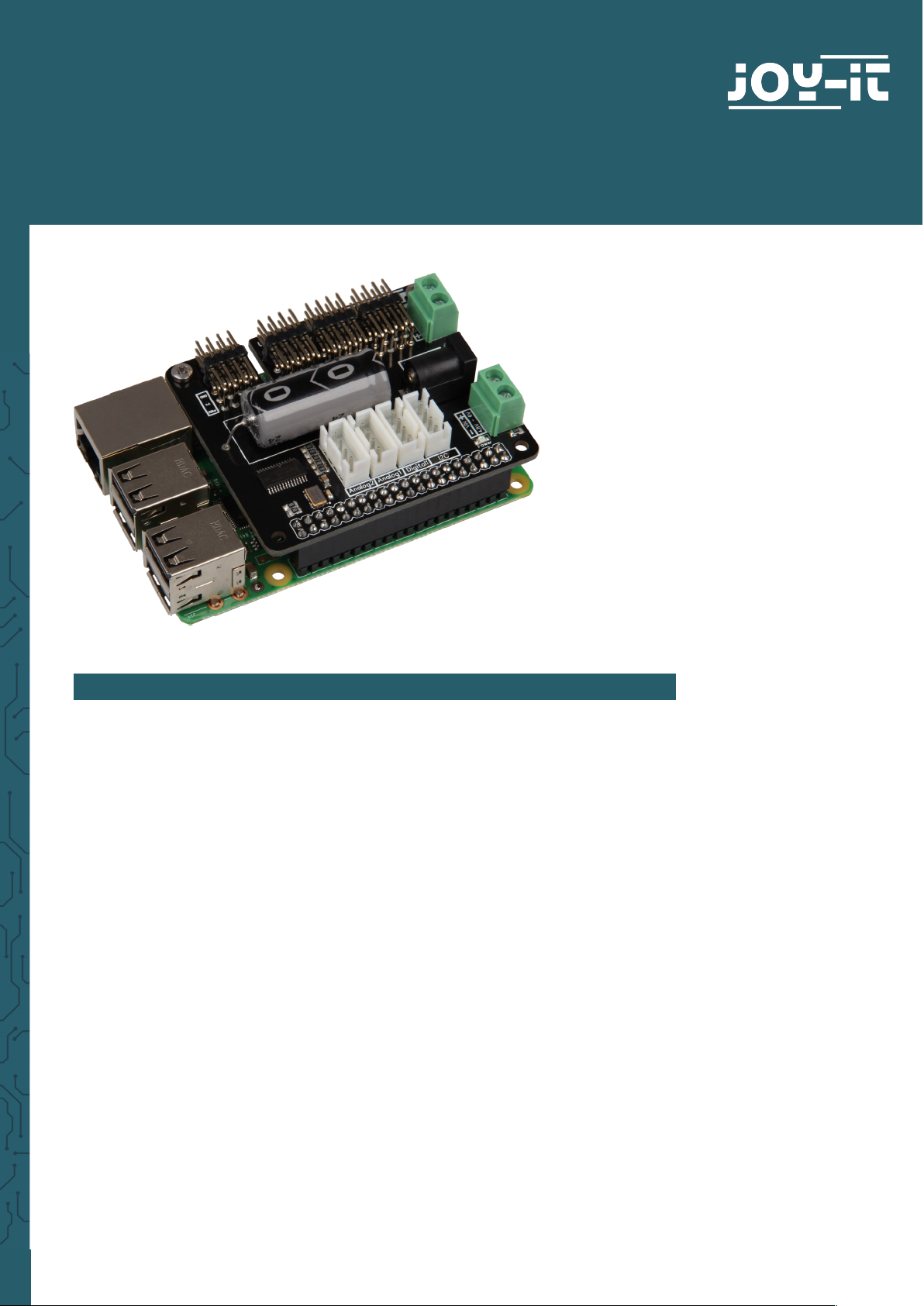
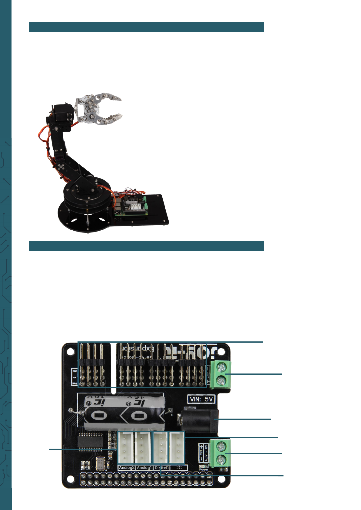
Joy-it MOTOPI User manual

www.joy-it.net
Pascalstr. 8 47506 Neukirchen-Vluyn
MOTOPI
Motor control for the Raspberry Pi
1. GENERAL INFORMATION
Dear customer,
Thank you for purchasing our product. In the following, we will show you
which things should be noted during the use.
Should you encounter any unexpected problems, do not hesitate to contact
us

www.joy-it.net
Pascalstr. 8 47506 Neukirchen-Vluyn
2. GENERAL
The MotoPi board is an expansion board for the control and use of up to
16 PWM controlled servomotors.
The board can be supplied additionally by 4.8 - 6 V so that the ideal
supply of the motors is always ensured and even greater projects can be
supplied by enough power.
It is for example perfectly suited for the control of the Joy-IT robot arm.
Article number: Robot02
The robot arm made of aluminium gets its
movement from 6 separately controllable 20 kg
motors. It is mounted on a based rotary plate
(360°). The base plate is made out of 4.5 mm
thick acryl and has mounng holes for all
common singleboard-computer and
microcontollers.
3. TECHNICAL DATA & SAFETY INSTRUCTIONS
The MotoPi board is equipped with 16 channels for 5V servomotors as
well as a possibility for connecting an additional capacitor.
Moreover, the board has 4 analog, 2 digital and a I2C connection facility.
The power supply is ensured by a 5 V coaxial power connector or via a
power supply between 4.8 and 6 V.
It is also additionally equipped with a quartz oscillator to keep
frequencies as precisely as possible and deviations as small as possible.
channel 0 - 15
connection for
an additional
capacitor
5 V DC input
4,8 - 6 V DC input
I2C
GND
5V
SDA
SCL
GND
5V
GPIO22
GPIO27
A0
A1
5V
GND
A2
A3
5V
GND
digital
analog

www.joy-it.net
Pascalstr. 8 47506 Neukirchen-Vluyn
On the backside of the board, the numeration of the channels can be
read.
The 3 pins of each channel are from top to bottom the connection for
ground, voltage and signal [GND | V+ | PWM].
The board can be plugged on the GPIO pins of the Raspberry Pi and the
cable of your 5V servomotors can be connected with the pins of the
channels.
An additional power supply via a cable or a 5V coaxial power connector is
mandatory necessary to operate.
To prevent sudden voltage drops, the board has a capacitor. If in special
cases this is not enough, you can connect an additional
capacitor parallel via the according connection.
The power supply must be adjusted to the power of the connected mo-
tors. If the power supply is insuiciently dimensioned, the motors will
stutter instead of moving smoothly. We recommend the use of our 4.8
power supply
RB-Netzteil2
which oers a 24 W continuous
output.
Aer pinning the expansion board on your Raspberry Pi, connecting an
additional power supply and connecting the servomotors, the board is
ready to use.
Safety instructions
To prevent inverse polarity, please note the markings on the board from the
according input (+ and - symbol).
An inverse polarity can cause damage to your board, the connected
Raspberry Pi and other peripheries!
The motors you connect and the movement they generate can be dange-
rous.
Therefore, we recommend suicient safety distance or rather to take
measurements so that no one can get in touch with the moving parts.

www.joy-it.net
Pascalstr. 8 47506 Neukirchen-Vluyn
4. INSTALLATION OF THE RASPBERRY PI
If you already use the latest Raspbian version on your Raspberry Pi, you
can skip the next step and start the next step.
The latest image of the operating system can be downloaded from the
Raspberry Pi website.
With the help of the Win32-Disk-Imager, you can copy the downloaded
image on your SD card.
Choose therefore, like shown in the picture below the image and your SD
card.
Aer that, you can start the writing process with
Write
.
If this step is successfull, you can put the SD card into yor Raspberry Pi
and continue to the next step.
5. INSTALLATION OF THE MODULE
To use the board properly, you should activate the two functions on your
Raspberry Pi: I2C and SPI
Therefore, open the configuration menu of the Raspberry Pi with the
following command:
sudo raspi-config
In the just opened window, navigate to the menu point
Interfacing Options
.

www.joy-it.net
Pascalstr. 8 47506 Neukirchen-Vluyn
Enable the function SPI.
Confirm the next windows all with Yes or rather Ok.
Aerwards, you must enable the function I2C.

www.joy-it.net
Pascalstr. 8 47506 Neukirchen-Vluyn
Confirm the next windows all with Yes or rather Ok.
Leave the configuration menu with
Finish
and restart your Raspberry Pi.
sudo reboot
Since the MotoPi is equipped with an additional crystal oscillator, a
special program library is required. This is based on the
Adafruit_PCA9685 Python library but it is specially adjusted for our board.
We recommend using unconditionally and exclusively our own adjusted
library. This library can be downloaded here .
Copy the unzipped library completely on your Raspberry Pi and navigate
in the terminal into this folder. With the following command you can
install the library.
sudo python setup.py install
Now Navigate into the folder
examples
and start the code example like
described below.
cd examples
sudo python simpletest.py
This test script shows the fundamental functions of the motor control
and the motor which is connected to the first channel, will move
repeatedly from one direction to the other.

www.joy-it.net
Pascalstr. 8 47506 Neukirchen-Vluyn
6. CONTROLL OF THE ADDITIONAL CONNECTIONS
Aer the restart, you must install the necessary drivers and modules.
Therefore perform the following commands:
sudo apt-get update
sudo pip install spidev
sudo pip install wiringpi
A restart is now required again.
sudo reboot
Aer the restart, the connections are ready to use.
Please note that the first pin of the digital connection is connected with
the GPIO pin 27 and the second pin to the GPIO pin 22.
7. CODE EXAMPLE TO USE THE DIGITAL CONNECTIONS
Here, you have a short code example for controlling the digital connec-
tions. For that, we use the
LK-Button1
with a
LK-Cable-20
from our Lin-
kerKit series.
import RPi.GPIO as GPIO
from time import sleep
#Initialisiere Button auf Digital-PIN 22
button = 22
GPIO.setwarnings(False)
GPIO.setmode(GPIO.BCM)
GPIO.setup(button, GPIO.IN, pull_up_down=GPIO.PUD_UP)
while True:
if GPIO.input(button) == GPIO.HIGH:
#Mache etwas
print "Ich tue etwas"
else:
#Mache etwas anderes
print "Ich tue etwas anderes"

www.joy-it.net
Pascalstr. 8 47506 Neukirchen-Vluyn
8. CODE EXAMPLE TO USE THE DIGITAL CONNECTIONS
Consecutively, you have a short code example for controlling the digital
connections. For that, we use the
LK-Joystick
with a
LK-Cable-20
from
our LinkerKit series.
Note that if not all connection are taken, the free pins can issue false
values.
import spidev
import time
import sys
spi = spidev.SpiDev()
spi.open(0,0)
spi.max_speed_hz = 2000000
def readadc(adcnum):
if adcnum >7 or adcnum <0:
return-1
r = spi.xfer2([1,8+adcnum <<4,0])
adcout = ((r[1] &3) <<8)+r[2]
return adcout
while True:
if len(sys.argv) >1:
for i in range(len(sys.argv)):
if i == 0:
print "_______________________________________\n"

www.joy-it.net
Pascalstr. 8 47506 Neukirchen-Vluyn
else:
adc_channel = int(sys.argv[i])
print "Channel " + str(adc_channel)
value=readadc(adc_channel)
volts=(value*3.3)/1024
print("%4d/1023 => %5.3f V" % (value, volts))
print " "
print "_______________________________________\n"
time.sleep(1.5)
else:
print "_______________________________________\n"
print "Channel 0"
value=readadc(0)
volts=(value*3.3)/1024
print("%4d/1023 => %5.3f V" % (value, volts))
print "Channel 1"
value=readadc(1)
volts=(value*3.3)/1024
print("%4d/1023 => %5.3f V" % (value, volts))
print "Channel 2"
value=readadc(2)
volts=(value*3.3)/1024
print("%4d/1023 => %5.3f V" % (value, volts))
print "Channel 3"
value=readadc(3)
volts=(value*3.3)/1024
print("%4d/1023 => %5.3f V" % (value, volts))
print "_______________________________________\n"
time.sleep(1.5)

www.joy-it.net
Pascalstr. 8 47506 Neukirchen-Vluyn
PR
9. OTHER INFORMATION
Our Information and Take-back Obligations according to the
German Electronic Law (ElektroG)
Symbol on Electrial and Electronic Products:
This crossed-out bin means that electrical and electronic products
do not belong into the household waste. You must hand over your old
appliance to a registration place. Before you can hand over the old
appliance, you must remove used batteries and replacement batteries
which are not enclosed by the device.
Return Options:
As the end user, you can hand over your old appliance (which has
essentially the same functions as the new one bought with us) free of
charge for disposal with the purchase of a new device.
Small devices, which do not have outer dimensions bigger than 25 cm
can be handed in for disposal independently of the
purchase of a new product in normal household quantities.
1. Possibility of return at our company location during our opening hours
Simac Electronics Handel GmbH, Pascalstr. 8, D-47506 Neukirchen-Vluyn
2. Possibility of return nearby
We will send you a parcel stamp with which you can send us your old
appliance free of charge. For this possibility, please contact us via e-mail
at service@joy-it.net or via telephone.
Information about Package:
Please package your old appliance safe for transport. Should you not
have suitable packaging material or you do not want to use your own
material, you can contact us and we will send you an appropriate
package.
10. SUPPORT
If any questions remained open or problems may arise aer your
purchase,we are available by e-mail, telephone and ticket
support system to answer these.
E-Mail: service@joy-it.net
Ticket-system: http://support.joy-it.net
Telephone: +49 (0)2845 98469 – 66 (10 - 17 o'clock)
For further information visit our website:
www.joy-it.net
Published: 16.04.2020
www.joy-it.net
SIMAC Electronics GmbH
Pascalstr. 8 47506 Neukirchen-Vluyn
This manual suits for next models
1
Table of contents
Other Joy-it Control Unit manuals

Joy-it
Joy-it rb-camera-WW2 User manual

Joy-it
Joy-it RB-LCD-20x4 User manual

Joy-it
Joy-it SBC-CAN01 User manual

Joy-it
Joy-it RB-LCD-16x2 User manual

Joy-it
Joy-it Buck and Boost User manual

Joy-it
Joy-it StromPi 3 Use and care manual

Joy-it
Joy-it DPS USB User manual

Joy-it
Joy-it ESP-01S User manual

Joy-it
Joy-it RB-MOTO2 User manual

Joy-it
Joy-it VAO10020 User manual