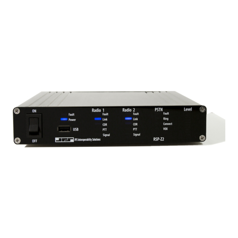
JPS RSP-Z2 User manual

RSP-Z2 Quick Start Guide
RSP-Z2 Quick Start Guide Page 2 of 8 Interoperability Now
Page intentionally left blank.

RSP-Z2 Quick Start Guide
Interoperability Now Page 3 of 8 RSP-Z2 Quick Start Guide
1RSP-Z2 Basic Overview
JPS Interoperability Solutions has several decades of experience with voice communications
interoperability, fielding their first devices in 1989. Over this time the company has encountered
and resolved a wide array of problems that can hamper or complicate communications when
disparate devices are patched together into interoperability nets.
The RSP-Z2 incorporates all this experience, in the form of a suite of sophisticated DSP
algorithms that operate at its interfaces with any connected communications devices, as well as
many custom radio interface cables, covering well over 300 different radio makes and models.
JPS interoperability devices are also known for simplicity and ease-of-use. The RSP-Z2’s
browser-based Graphical User Interface is carefully designed to make these sophisticated
capabilities available when necessary. When the simple setup and configuration works well, an
installer and operator need only be concerned with these elements. However, if the
communications system includes any problematic elements, a JPS interoperability device (such
as this RSP-Z2) has the features necessary to resolvethe problems and optimize communications.
The RSP-Z2 provides a pair of local-to-IP backhaul channels, along with a USB Headset
Channel. The non-headset channels can be configured in multiple ways, as illustrated below.

RSP-Z2 Quick Start Guide
RSP-Z2 Quick Start Guide Page 4 of 8 Interoperability Now
Independent Passthrough
This configuration provides two separate IP-to-IP or Analog-to-IP converters. For each, active
COR on the local side will send incoming audio out the IP backhaul interface, and vice-versa.
Active COR occurs when the channel determines that “Valid” audio input has been detected.
Available COR types (methods of determining valid audio) vary by channel type.
Note that four separate channels are depicted for this configuration –two local audio channels
each tied to its own IP backhaul channel. A USB Headset can also be included and connected to
any communications channel.
Cross-Connected
This configuration patches the two local interfaces together, with no IP backhaul. When one of
the two channels detects a valid audio input, the other will transmit this audio.
Whenever any user from either system transmits on the designated channel/talkgroup, all other
users on both channels can hear. Because donor radios are used to interface the system,
identically to all other radios in each system, the RSP-Z2 installation has minimal impact.
Cross-Connected with Backhaul
This is a combination of the Independent Passthrough and the Cross-Connected configurations.
Only a single backhaul interface is needed, because it is interfaced to the combined (cross-
connected) audio of the two local channels.
1.1 Channel Types and Channel Profiles
The RSP-Z2 provides significant assistance in configuring any of the variety of channel types
available to interface audio devices. Each channel type has a default profile and context-sensitive
help in the GUI provides additional assistance in tuning channels to meet your needs. Once a
channel has been tuned to your preferences, save the settings as a new, custom profile to make it
easy to apply to another channel.
Local Channel Type options include:
•Radio (also appropriate for other types of four-wire devices).
•RoIP (JPS-proprietary Radio over IP), RTP, and SIP (BSI compliant).
•USB Headset.
•Various Push-to-Talk over Cellular channels.
Backhaul Channel Type options include:
•Bridge (used to interface to other JPS Z-Series devices, e.g. ACU-Z1, Z2 Controller).
•RoIP, RTP, and SIP.
•Various Push-to-Talk over Cellular channels.

RSP-Z2 Quick Start Guide
Interoperability Now Page 5 of 8 RSP-Z2 Quick Start Guide
2Procedures
All the information necessary to install, configure, and operate the RSP-Z2 is available within
the unit. This Quick Start Guide’s primary purpose is to describe how to access that information.
The RSP-Z2 is standards-compliant and therefore supports standards-compliant web browsers,
including Internet Explorer (must be IE 10 or higher), Edge, Firefox, Chrome, Opera and Safari.
It is always best to use the most current version of any web browser.
2.1 Set up IP Address and Subnet Mask
As with any device with a static IP address, it will be necessary to configure the unit to operate
on the LAN where it is to be deployed. The RSP-Z2’s factory default IP address is
192.168.1.200, with a default subnet mask of 255.255.255.0.
To reset to an address and subnet mask that work on your LAN, connect the RSP-Z2 via Ethernet
cable (need not be a cross-over cable, though a cross-over cable will work) directly to the
Ethernet port of the computer that will be used to access and configure it.
Using your PC network settings options, set the computer to a static IP address of 192.168.1.xxx
(where xxx is a number between 2 and 199) and a subnet mask of 255.255.255.0. This will allow
you to browse to the RSP-Z2 at its default IP address following the instructions below.
Plug in the unit’s power supply and turn the unit on via its front panel power switch. The RSP-
Z2’s front panel LEDs will flash while the unit boots up (approximately 90 seconds).
Upon browsing to the RSP-Z2’s IP address, the login screen (shown below) will appear.
The default name and password are both “su” for superuser with the superuser’s full-
capability permission set.
For best security, it is strongly advised to change the default username and password before
putting the unit in service, however it is not required to continue setup. Changing usernames and
passwords can be done under Security in the RSP-Z2 GUI; instructions and explanations can be
found in the RSP-Z2 Installation and Operation Manual.
2.2 Network Settings
To change network settings, click Settings from the top banner and then Network from the tab
options. The following dialog box will be available for changing system parameters. (Note that
these are not the system default settings).

RSP-Z2 Quick Start Guide
RSP-Z2 Quick Start Guide Page 6 of 8 Interoperability Now
After entering the new IP address and subnet mask, write them down for safekeeping. Once
you have written the new IP address and subnet mask down, press Submit. The unit will reboot
to integrate the new settings. Once it has rebooted, log in again at the new IP address.
If the IP address and subnet mask are ever misplaced or lost, the unit can be interrogated for its
current settings. Refer to the Installation and Operation Manual for instructions.
2.3 Using the RSP-Z2
2.3.1 Summary: Radio Channel Setup on a local channel
The following instructions serve as a simplified outline of the process. Best use of all
communications technologies may require additional fine tuning. Refer to your JPS radio cable
Applications Notes as well as the RSP-Z2 Installation and Operation Manual for additional
valuable information.
Choose an RSP-Z2 Configuration
If a configuration has not been selected, choose one from the RSP-Z2 Home page by
either clicking on one of the three configuration options or choosing one from the
dropdown list at the top of the page. This will apply that configuration of channels to the
RSP-Z2.
Assign Channel Type
Select the Channel tab from Settings. This displays all of the RSP-Z2’s channels. A
question mark means no channel type has been chosen. Click a channel to select it from
the list along the top. In the Basic Settings box, select Radio from the channel Type pull-
down menu.
Channel Profile
The Default radio channel Profile information will populate to all the other configuration
boxes once the Radio channel Type has been chosen. Numerous other specific radio
profiles are pre-loaded and can save you time. Refer to the Installation and Operation
Manual for additional information.

RSP-Z2 Quick Start Guide
Interoperability Now Page 7 of 8 RSP-Z2 Quick Start Guide
Additional Channel Configuration Settings
Help with configuration settings is always available by clicking the question mark for
context-sensitive help.
2.3.2 Front Panel Level Indicator
The RSP-Z2 has a set of audio level indicating LEDs on the front panel. The indicator can be
applied to any one of the unit’s channels. The level shown is the selected channel’s external RX
input after the channel's Receive (Input) Level audio adjustment has been applied. This allows
the indicator to give visual evidence of optimal adjustment which should be the same for every
channel. When the Receive Input Level is properly set, the first red LED on the Level Meter will
flash red on voice peaks for a person speaking at a normal volume, for example a few times a
second, depending on speech cadence.
Click on the icon with the rising bars in the upper right of each interface to select which channel
is using the level meter. (These bars only visible after configuration is set). After selection, the
level icon in the selected channel will turn green.
2.3.3 USB Headset
If a JPS-approved USB headset is plugged in at power-up, an icon will appear in the upper right
corner of CH1 and CH2. Click on one of these headset icons to select what audio source it will
be connected to. This selection makes a difference only for the Independent Passthrough
configuration, because with all other configurations, all the channels are patched together.
Figure above: Home Screen with Headset plugged in but not yet selected. Level Indicator also
not yet selected.

RSP-Z2 Quick Start Guide
RSP-Z2 Quick Start Guide Page 8 of 8 Interoperability Now
2.4 Accessing Help
•The RSP-Z2’s Help Documents, in PDF format, can be viewed or downloaded from this
unit. Click the Help pull-down menu to display a list of available documents. The RSP-
Z2 Manual and Quick Start Manual are also available on the JPS website.
•Context-sensitive help is available within the unit’s browser-based Graphical User
Interface by clicking on the question marks located throughout.
End of RSP-Z2 Quick Start Guide
Other manuals for RSP-Z2
2
Table of contents
Other JPS Gateway manuals
Popular Gateway manuals by other brands

Rohde & Schwarz
Rohde & Schwarz R&S GW5420 installation manual

TVILIGHT
TVILIGHT Gateway 3.1 installation manual

Advantech
Advantech SMARTSWARM 300 Series user manual

Dialogic
Dialogic IMG 1010 quick start guide

MSA
MSA fieldserver QuickServer FS-QS-2 0 Series Startup guide

RTA
RTA 460MSUS-NNA1 Product user guide