JPS Z Series User manual

Z-Series Audio Optimization Guide
Z-Series Audio Optimization Guide Page 2 of 10 Interoperability Now
Table of Contents
1GENERAL..........................................................................................................................................3
2BEFORE YOU BEGIN......................................................................................................................4
2.1 JPS CHANNEL PROFILES.................................................................................................................4
2.2 LOCAL HANDSET AND/OR USB HEADSET......................................................................................4
2.3 RADIO INTERFACE CABLES.............................................................................................................4
2.3.1 JPSRADIO INTERFACE CABLES 4
2.3.2 CUSTOMER-DESIGNED RADIO CABLES 5
3AUDIO ADJUSTMENTS..................................................................................................................6
3.1 RECEIVE (INPUT)LEVEL –(RX AUDIO LEVEL) ............................................................................6
3.2 TRANSMIT (OUTPUT)LEVEL –(TX AUDIO LEVEL)......................................................................7
3.3 TRANSMIT DELAY (TX AUDIO DELAY)..........................................................................................7
3.4 RECEIVE DELAY (RX AUDIO DELAY) ............................................................................................8
3.5 AUDIO LEVELS AND DELAYS FOR VIRTUAL OR BACKHAUL CHANNELS .....................................8
3.6 VOX THRESHOLD............................................................................................................................8
4TROUBLESHOOTING TIPS...........................................................................................................9
4.1 SYMPTOMS:USER IN FIELD COMPLAINS OF MISSED FIRST SYLLABLES.....................................9
4.2 SYMPTOMS:USER IN FIELD COMPLAINS OF MISSED SYLLABLES MID-CONVERSATION...........9
4.3 SYMPTOMS:RADIO CHANNEL EXPERIENCING CONTINUOUS ACTIVE COR STATE...................9
4.4 SYMPTOMS:AUDIO SOUNDS TOO WEAK.......................................................................................9
4.5 SYMPTOMS:AUDIO SOUNDS TOO LOUD OR DISTORTED ............................................................10
4.6 SYMPTOMS:FALSE KEYING OF DONOR RADIO BY RADIO CHANNEL........................................10
4.7 SYMPTOMS:CROSS-CONNECTED RADIOS CONTINUOUSLY KEY EACH OTHER.......................10

Z-Series Audio Optimization Guide
Interoperability Now Page 3 of 10 Z-Series Audio Optimization Guide
1General
The purpose of this supplemental Z-Series Audio Optimization Guide is to assist users with
adjustments of the Z-Series channel interfaces for optimal audio performance with the varying
communications systems encountered in the field.
This guide is an adjunct to the Installation and Operation Manual and the context-sensitive help
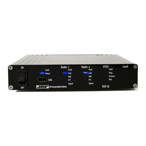
in the Graphical User Interface (GUI) of the Z-Series device (i.e. ACU‑Z1 or RSP‑Z2) you are
using. Please refer to the appropriate manual and context-sensitive help for your device prior to
consulting this document. By doing so, you will have the required basic understanding of the
various configuration settings options as well as instructions for basic setup.
Reminder:Virtual channels (JPS Bridge and JPS RoIP) representing radio channels managed by
a Z2 Controller or an ACU‑Z1 are not interfaced directly to radio systems. Radio channel
configuration must be done on the device (ACU‑Z1 or RSP‑Z2) interfaced to the radio system.

Z-Series Audio Optimization Guide
Z-Series Audio Optimization Guide Page 4 of 10 Interoperability Now
2Before You Begin
There are several paths to optimization; the items listed in this section will play a significant part
in determining the ideal path.
2.1 JPS Channel Profiles
The JPS Channel Profiles embedded in each Z-series product speed the setup process by
automatically setting the Z-Series device’s radio interface configuration options to those listed
in the Application Note that accompanies the cable. These settings are correct only when using
the associated JPS cable.
Note: Channel profiles and application notes provide a good starting point, but a channel may
require additional adjustments. For this reason and for general convenience, users can also create
and save their own channel profiles.
2.2 Local Handset and/or USB Headset
The Handset included with the ACU‑Z1, or a properly configured USB Headset can be helpful
because it allows a known baseline interface (the handset or headset) to be compared to a (yet
unproven) interface. For example, assume a problem is encountered when interfacing two radios
to the Z-Series device, or interfacing a radio to a JPS RoIP backhaul channel. Use the handset or
the headset to connect to each of the channels individually in turn. This will quickly identify the
problematic channel.
Recommendation: It is best to initially set up and optimize each channel while it is connected to
the handset or headset only, and then cross-connect the other two (now fully proven) channels to
each other.
Note: For a list of headsets, refer to the table Optional Equipment - Not Supplied in the unit’s
Installation and Operation Manual.
2.3 Radio Interface Cables
2.3.1 JPS Radio Interface Cables
JPS provided Radio Interface Cables were designed by JPS Systems Engineers who investigated
the radio’s analog interfaces, then designed an appropriate interface between the radio and the
JPS equipment and verified it in the lab. Some interfaces are simple, others are not so. Some
require DC blocking capacitors or unusual level-setting networks. The JPS cables include a small
circuit board that properly interfaces with radio hardware for hundreds of different radio makes
and models. For these reasons, JPS cables are always the best option for interfacing a radio to the
ACU‑Z1, RSP‑Z2, or other JPS gateways.
The cable should easily connect to the radio; many are built by splicing a cable manufactured for
the specific radio to the appropriate signal lines on the JPS cable.

Z-Series Audio Optimization Guide
Interoperability Now Page 5 of 10 Z-Series Audio Optimization Guide
Follow the instructions of the Application Note that came with the cable. If you are missing this
Note are:
•Configuration settings for the Radio Channel, optimized for the JPS Cable when used
with the associated radio.
Note:The Application Notes were created for use with a variety of JPS gateways;
pay attention only to the configuration settings available on the Radio Channel
Settings Page in the Z-Series GUI.
•Changes required or suggested for the radio itself, either in its configuration or
programming.
If you apply the Channel Profile for the radio, the profile will automatically apply the appropriate
configuration settings as a reasonable starting point.
Once appropriate configuration settings for the radio have been applied, the next step is to take
care of optimization and/or settings that should be adjusted prior to system use. Most of the
following are best accomplished using a test count from a “companion radio” that is in
communication with the donor radio cabled to the Z-Series device. A companion radio is from
the same radio system, not a cross-connected radio. Listen using a USB headset or the handset
(ACU‑Z1), or to another device cross-connected via the Z-Series device with the donor radio.
2.3.2 Customer-Designed Radio Cables
For customers who plan to create their own radio interface cables, JPS strongly recommends
using the Unterminated Radio Cable, JPS P/N 5961-291115. This shielded cable includes the
DB-15 end of the cable that plugs into the Z-Series device analog ports, along with the small
printed circuit boardthat is in other JPS cables. This circuitry has avariety of variable attenuating,
terminating, and DC-blocking components; essentially everything that JPS Systems Engineers
have deemed necessary to interface any of the several hundred types of radios they have created
custom cables for. This seven-pin cable is unterminated on the radio side, allowing the radio
specific portion of the cable to be spliced on.
The Application Note for this cable contains information to help in the cable design and, in
particular, explains how to determine which of the various configuration options is best (e.g. how
to decide how to choose between the COR options of VOX, VMR, or Hardware COR).
The Application Note information for unterminated cables is useful but will not be repeated in
this document. Application Notes for all JPS Custom Radio Cables, including the Unterminated
Radio Cable, are shipped with the cable. Additional copies may be obtained by contacting JPS
Customer Support.
Note: Older versions of the Unterminated Radio Cable Application Note relate to its use with
non-Z-Series devices, such as the ACU-2000 or the NXU-2B. All relevant information applies
to Z‑Series devices.

Z-Series Audio Optimization Guide
Z-Series Audio Optimization Guide Page 6 of 10 Interoperability Now
3Audio Adjustments
3.1 Receive (Input) Level – (RX Audio Level)
The Receive Input levels in the Z-Series device GUI indicate the actual level of audio being
received. If the incoming level is -12 dB, the Receive Input setting of the Radio Channel should
be set to -12 dB. This must beunderstood to know which way to change theaudio level for proper
operation. If/when the Radio Channel, when set to -12 dB, is not receiving enough audio, the
number in the GUI must be set to a lower number (e.g. -16, -20, etc.) to correspond to the actual
input level. The Z-Series device will then apply additional gain/reduced attenuation.
Some minor adjustment may be required, mainly due to radio-to-radio variations.
One way to make sure the level is correct is to use a companion radio to communicate with the
donor radio. Verify the proper Receive Input by speaking into the microphone of the companion
radio in a normal voice and watch the front panel LED of the Z-Series device.
•ACU‑Z1 –Set the ACU‑Z1 audio knob mid-way for the radio channel being set up;
monitor the front panel Signal LED for the associated module. While receiving audio
from somebody speaking at a normal level, the Signal LED should flash green on voice
peaks, for example on every syllable or a few times a second, depending on speech
cadence. It should not be lit continuously while speech is coming in, but a normal
speaking level should create occasional flashes. If the incoming speech never causes the
green Signal LED to flash, lower the Receive Input level until the flashes are occasional
only. Conversely, if all speech causes green Signal LED flashes, raise the Receive Input
level until the flashes are occasional only.
•RSP-Z2 –Associate the RSP-Z2 Front Panel Level meter with the donor radio interface
by clicking the Level Meter on the Home Screen. Proper setting results in occasional
flashes of a single red LED on voice peaks for a person speaking at a normal volume, for
example a few times a second, depending on speech cadence. It should not be lit
continuously while speech is coming in, but a normal speaking level should create
occasional flashes. If the incoming speech never causes the red LED to flash, lower the
Receive Input level until the flashes are occasional only. Conversely, if all speech causes
red LED flashes, raise the Receive Input level until the flashes are occasional only.

Z-Series Audio Optimization Guide
Interoperability Now Page 7 of 10 Z-Series Audio Optimization Guide
3.2 Transmit (Output) Level – (TX Audio Level)
The Transmit Output level should be set to properly modulate the donor radio transmitter. Audio
coming from the donor radio, when doing a normal voice volume radio count, should be heard
in the companion radio at the same level as received conversations from other radios in the system
(as heard in the companion radio).
•If you have a headset or handset (ACU‑Z1), cross-connect it with the radio interface so
that speaking into the headset/handset causes the donor radio to transmit.
•If you do not have a headset or handset, you will need to cross-connect another channel
that has its RX audio level properly set up (e.g. a second radio channel or a backhaul
channel).
Note: Doing the RX audio level adjustment before setting the TX audio level (or using a handset
or headset) and verifying it via the front panel LED will help prevent a mutually-erroneous
condition where a too-low RX audio input is compensated by a too-high TX audio input on a
cross-connected channel. This condition is particularly troubling whenever a third interface is
introduced to the system –its incoming audio will be too low for one of the mutually erroneous
interfaces and too high for the other.
3.3 Transmit Delay (TX Audio Delay)
If the donor radio is used with a trunked radio system, it may be necessary to adjust the TX audio
delay. If initial syllables are missing in the received audio of the companion radio (when listening
to transmissions from the Z-Series device/donor radio) increase the TX audio delay of the Z-
Series interface connected to that donor radio.
The test for determining the proper TX Delay is best done when talking into a USB headset (or
handset on the ACU‑Z1) that is cross-connected with the radio interface, rather than some other
interface. The reason is that using the headset or handset precludes any chance that any audio is
missing initial syllables before being sent to the donor radio to be transmitted to the trunking
system.
Note that a different audio delay setting, RX Delay (below), must be increased if initial syllables
are clipped on the incoming audio of a Radio Channel. If you are using a cross-connected radio
channel instead of a handset or headset for determination of the proper TX Delay setting, and
additional increases in TX Audio Delay have no effect on missed first syllables in the field radio,
then it may instead be necessary to increase the RX Audio Delay in that cross-connected Radio
Channel. It is an uncommon but possible condition.
Explanation for TX Delay: When a radio user initiates a transmit sequence for a trunked
radio, that user depresses the PTT switch on the radio, which sends a signal to the
system’s trunking controller, asking to be assigned to a free (not currently busy) channel.
The duration of time required for channel acquisition varies according to availability.
Once the trunking controller determines a channel, it sends a signal back to the user’s
radio that automatically sets the radio to a free channel, and it signals this to the radio
user by a tone called a channel acquisition tone or simply a go-ahead tone. The trunked
system radio user is trained to not begin talking until this tone is heard.
Unfortunately, this tone cannot be heard by users on other systems that are cross-
connected by the Z-Series device to the trunked radio system. If the user is on a non-radio

Z-Series Audio Optimization Guide
Z-Series Audio Optimization Guide Page 8 of 10 Interoperability Now
device, that user is accustomed to simply begin talking. This means that, without
intervention by the Z-Series device, the beginning of that user’s message will be clipped,
and only what the user says after the trunked system finishes acquiring the channel will
be heard. The same is true for any cross-connected users with non-trunked radios, they
will simply press PTT and begin talking. This “clipping of initial syllables in TX audio”
is resolved in the Z-Series device by adding TX audio delay at the unit’s radio interface
to the donor radio for the trunked radio channel. The TX Delay keys up the radio
immediately, but holds up the audio, storing it in a buffer, until enough time has gone by
for a typical channel acquisition time to have elapsed. The trunked radio is then ready to
accept the audio to be transmitted, and the Z-Series device’s audio buffer then begins
spooling it out.
3.4 Receive Delay (RX Audio Delay)
Delay in the RX audio occurs by processing the COR detection immediately while holding the
incoming audio in a buffer and spooling it out after the set delay time. This resolves the
(uncommon) condition for a Radio Channel where the COR indication or detection occurs late
and initial incoming syllables are therefore clipped.
The Z-Series Radio Channel interfaces are designed to prevent this as well as is practical, through
proper design of the various COR Detection algorithms and by including a minimum RX Audio
Delay for VOX and VMR. Additional VOX delay can be added if needed, however it will
increase latency. Prior to adjusting RX Delay, you might try lowering the VOX Threshold,
increasing the radio volume, or decreasing the RX Audio Level setting.
3.5 Audio Levels and Delays for Virtual or Backhaul Channels
In most cases, there are no associated configuration options for RX or TX level settings, or to
change RX or TX audio delays for the JPS RoIP, RTP, and JPS Bridge virtual or backhaul
channels. However, some PTT over Cellular channels feature an RX Gain setting, and TX Delay
and VOX Sensitivity are both configuration settings for SIP. In most instances, modifying the
levels or delays for these channel types is done at the audio input or output channels feeding or
receiving analog audio. Audio on these channel types should be modified following (i.e. after)
optimization of all analog interfaces.
For example, let’s say a pair of RSP-Z2s (or ACU-Z1s) is used to connect radios over IP (RoIP)
that are on opposite sides of the world. If the RX input of each radio is correct, the level received
by the distant radio on the other side of the JPS RoIP link will be correct. If audio is set too low
coming into the RSP-Z2 on the local radio, it will also be too low coming out of the remote
RSP‑Z2.
3.6 VOX Threshold
The VOX threshold may benefit from optimization (either more or less sensitive) due to system
variations or user preferences. More sensitive means less audio level must be detected for the
incoming audio to be declared valid. Less sensitive is the opposite (i.e. more audio must be
detected for the incoming audio to be declared valid). Increased sensitivity makes it more likely
that falsing (declaring the input valid when it is not) will occur; decreased sensitivity increases
the potential that valid speech may be missed. Changes may be desired due to level of static on
the channel, quiet talkers, or desire to never miss any audio, even if some falsing occurs.

Z-Series Audio Optimization Guide
Interoperability Now Page 9 of 10 Z-Series Audio Optimization Guide
4Troubleshooting Tips
These troubleshooting tips should resolve some ofthe most common problems encountered when
setting up a radio interface. If you find that you are still encountering difficulties, please contact
4.1 Symptoms: User in Field Complains of Missed First Syllables
▪Cause: Donor radio is trunked, need to compensate for Channel Acquisition Delay.
▪Cause: Slow-to-key transmitter on donor radio.
▪Cause: Secure donor radio, need to compensate for encryption or scrambling.
✓Solution: Increase Transmit (TX) Audio Delay in the donor radio’s Radio Channel on the
Z-Series device.
4.2 Symptoms: User in Field Complains of Missed Syllables Mid-Conversation
▪Cause: Dropout from Radio Channel using VOX or VMR COR Detection Type.
✓Solution: Increase VOX or VMR Hangtime of the Radio Channel supporting the donor
radio.
✓Solution: Verify the Receive Audio Level is correct. Make VOX more sensitive for the
Radio Channel supporting the donor radio.
4.3 Symptoms: Radio Channel Experiencing Continuous Active COR State
▪Cause: Donor radio is introducing continuous noise to Radio Channel.
▪Cause: Donor radio is non-FM type, without the quieting characteristic of a frequency
modulated signal. These are most likely Amplitude Modulated radios, such as commonly
used by aircraft, or HF/single-side band (SSB) radios. They typically lack a Hardware
COR output and high noise level causes VOX to false on the noise.
✓Solution: Change COR Detection Type to VMR.
4.4 Symptoms: Audio Sounds Too Weak
▪Cause: Received audio level from donor radio (or other device type) is too low; verify
using ACU‑Z1 front panel Signal LED or the RSP-Z2 front panel level indicator.
✓Solution: Change Receive (Input) Level audio setting of the receiving channel until the
corresponding Signal LED (or the first red LED on the level indicator of the RSP-Z2)
flickers with voice peaks of incoming speech.
Note: The number in the Z-Series device GUI indicates the actual level of audio being
received. If the incoming level is -12dBm, the Receive (Input) Level setting of the Radio
Channel should be set to -12dBm. If the channel is not receiving enough audio, the
number in the GUI must be set to a lower number to correspond to the actual input level.
The Z-Series device will then apply additional gain or attenuation per the setting change.
▪Cause: Transmit audio level delivered to donor radio is too low.
(Solution on next page.)

Z-Series Audio Optimization Guide
Z-Series Audio Optimization Guide Page 10 of 10 Interoperability Now
✓Solution: First –and this is important –it is extremely wise to make sure the Receive
Audio Levels are set properly. Only after doing so, increase Transmit (Output) Level of
transmitting Radio Channel until donor radio is properly modulated.
4.5 Symptoms: Audio Sounds too Loud or Distorted
▪Cause: Receive audio level from donor radio (or other device) is too high.
✓Solution: Change Receive (Input) Level audio setting of the receiving channel until the
corresponding Signal LED (or the first red LED on the level indicator of the RSP-Z2)
flickers with voice peaks of incoming speech; not on at all times when speech is received.
✓Note: The number in the Z-Series device GUI indicates the actual level of audio being
received. If the incoming level is -12dBm, the Receive (Input) Level setting of the Radio
Channel should be set to -12dBm. If the channel is not receiving enough audio, the
number in the GUI must be set to a lower number to correspond to the actual input level.
The Z-Series device will then apply additional gain or attenuation per the setting change.
▪Cause: Transmit audio level delivered to donor radio too high.
✓Solution: First –and this is important –it is extremely wise to make sure the Receive
Audio Levels are set properly. Only after doing so, lower the Transmit (Output) Level of
transmitting Radio Channel until donor radio is properly modulated.
4.6 Symptoms: False Keying of Donor Radio by Radio Channel
▪Cause: Extraneous RFI emissions present at frequency/level that keys a donor radio.
✓Solution: Eliminate RFI emission source.
✓Solution: Transmit power of other, nearby donor radios may be higher than your system
needs. If there is a power setting, reduce to no more than necessary to link to repeater.
✓Solution: Modify antenna placement.
✓Solution: Change COR Detection Type to VMR.
4.7 Symptoms: Cross-Connected Radios Continuously Key Each Other
▪Cause: This phenomenon, known as “Ping-Pong”, is caused by the tendency of some
radios to temporarily unsquelch at the end of a transmit sequence. This momentary Active
COR condition in a donor radio (Radio 1) will cause a momentary transmit sequence in
devices cross-connected to that donor radio. If one of the cross-connected devices is
another donor radio (Radio 2) with the same momentary unsquelch at the end of a transmit
sequence, then the Radio 1 momentary unsquelch will key Radio 2, whose resulting
momentary unsquelch keys Radio 1 in a continuing sequence.
✓Solution: Use the COR Inhibit (after PTT) time function to make the Z-series radio
channel ignore an incoming Active COR signal for a short time after the channel ends a
PTT session. Watch the COR LED on the Z-Series device and increase the COR Inhibit
time until the COR LED no longer flashes at the cessation of PTT.
✓Solution: Change COR Detection Type to VMR
This manual suits for next models
2
Table of contents
Other JPS Gateway manuals