JPS RSP-Z2 User manual

RSP-Z2 Operations Manual
RSP-Z2 Installation and Operation Manual 2 Interoperability Now
FEDERAL COMMUNICATIONS COMMISSION
(FCC) COMPLIANCE NOTICE:
RADIO FREQUENCY INTERFERENCE NOTICE
This equipment has been tested and found to comply with the limits for a Class A
digital device, pursuant to Part 15 of the FCC Rules. These limits are designed to
provide reasonable protection against harmful interference when the equipment is
operated in a commercial environment. This equipment generates, uses, and can
radiate radio frequency energy and, if not installed and used in accordance with the
instruction manual, may cause harmful interference to radio
communications. Operation of this equipment in a residential area is likely to cause
harmful interference in which case users will be required to correct the interference at
their own expense.
CAUTION
Changes or modifications to this equipment not expressly approved by JPS
Interoperability Solutions could impair proper operation of the equipment and/or
could void user’s warranty.
NOTICE
JPS Interoperability Solutions reserves the right to make changes to the
equipment and specifications without prior notice.
PROPRIETARY STATEMENT
The information contained in this manual is the property of JPS Interoperability
Solutions and is intended for the purchaser’s use only. It may not be reproduced
without the expressed written consent of JPS Interoperability Solutions, Inc.
RSP-Z2 is a trademark of JPS Interoperability Solutions, Inc.
© 2018-2021 JPS Interoperability Solutions, Inc.

RSP-Z2 Operations Manual
Interoperability Now 3 RSP-Z2 Installation and Operation Manual
Table of Contents
1RSP-Z2 OVERVIEW......................................................................................................................1-1
1.1 SCOPE ............................................................................................................................................1-1
1.2 IMPORTANT DEFINITIONS: ...........................................................................................................1-1
1.3 POSSIBLE RSP-Z2 CONFIGURATIONS .........................................................................................1-2
1.3.1 INDEPENDENT PASSTHROUGH 1-2
1.3.2 CROSS-CONNECTED 1-4
1.3.3 CROSS-CONNECTED WITH BACKHAUL 1-5
1.4 CONTEXT-SENSITIVE HELP..........................................................................................................1-6
1.5 FRONT PANEL LEVEL INDICATOR...............................................................................................1-6
1.6 USB HEADSET...............................................................................................................................1-7
1.7 CONFIGURATION AND CONTROL METHODOLOGY ....................................................................1-8
1.8 SPECIFICATIONS............................................................................................................................1-9
1.9 EQUIPMENT AND ACCESSORIES SUPPLIED ...............................................................................1-10
1.10 OPTIONAL EQUIPMENT:NOT SUPPLIED .................................................................................1-10
2INSTALLATION............................................................................................................................2-1
2.1 GENERAL.......................................................................................................................................2-1
2.2 UNPACKING AND INSPECTION......................................................................................................2-1
2.3 RESHIPMENT OF EQUIPMENT ......................................................................................................2-1
2.4 INSTALLATION CONSIDERATIONS ...............................................................................................2-2
2.5 MECHANICAL PACKAGE ..............................................................................................................2-2
2.6 CONNECTORS,CONTROLS,AND INDICATORS.............................................................................2-3
2.7 RADIO INTERFACE AND CABLES..................................................................................................2-4
2.8 POWER SOURCE............................................................................................................................2-4
2.9 SAFETY PRECAUTIONS AND PROCEDURES..................................................................................2-5
2.10 MAINTENANCE............................................................................................................................2-5
3WEB-BASED CONFIGURATION...............................................................................................3-1
3.1 SET UP IP ADDRESS AND SUBNET MASK.....................................................................................3-1
3.2 LOG IN...........................................................................................................................................3-1
3.3 NETWORK CONFIGURATION........................................................................................................3-2
3.3.1 IP ADDRESS DETERMINATION AND CHANGE VIA USB PORT 3-2
3.3.2 FIRMWARE UPDATE 3-3
4SECURITY - USER TYPES AND PERMISSIONS....................................................................4-1
5RSP-Z2 CONFIGURATION .........................................................................................................5-1
5.1 BASIC SYSTEM CONFIGURATION SELECTION.............................................................................5-1
5.2 CHANNEL SELECTION AND SETTINGS CONFIGURATION ...........................................................5-3
5.3 CHANNEL SETTINGS .....................................................................................................................5-4
5.4 CHANNEL PROFILES .....................................................................................................................5-7

RSP-Z2 Operations Manual
RSP-Z2 Installation and Operation Manual 4 Interoperability Now
5.5 CHANNEL PROFILES BASIC INFORMATION...............................................................................5-10
5.6 CHANNEL SETTINGS –UNIVERSAL............................................................................................5-11
5.6.1 BASIC SETTINGS 5-11
5.6.2 AUDIO PRIORITY 5-12
5.7 LOCAL CHANNEL SETTINGS –USB HEADSET..........................................................................5-14
5.8 LOCAL CHANNEL SETTINGS –RADIO .......................................................................................5-15
5.9 IP-BASED CHANNEL SETTINGS –BRIDGE,ROIP, RTP, AND SIP............................................5-19
5.9.1 ENCRYPTION ON JPS BRIDGE AND JPS ROIP CHANNELS 5-19
5.9.2 BRIDGE 5-20
5.9.3 JPS ROIP 5-20
5.9.4 RTP 5-20
5.9.5 SIP 5-20
5.10 PUSH-TO-TALK OVER CELLULAR (PTTOC) CHANNEL SETTINGS .......................................5-21
5.10.1 JPS ROIP-BASED PTTOCCHANNELS 5-22
5.10.2 KODIAK/MSI-BASED PTTOCCHANNELS 5-23
5.11 LICENSED ENHANCEMENTS:ENCRYPTION ON JPS ROIP AND BRIDGE CHANNELS............5-24
5.12 RETURNING CONFIGURATION AND CHANNEL SETTINGS BACK TO FACTORY DEFAULTS..5-25
6OPERATING INSTRUCTIONS...................................................................................................6-1
6.1 USB HEADSET OPERATION..........................................................................................................6-2
6.1.1 USB HEADSET OPERATION,PTT MODE 6-5
6.2 DIAL OUT OPERATION .................................................................................................................6-6
6.3 LIVE STATUS INFORMATION........................................................................................................6-8
7RECENT UPGRADES TO THE RSP-Z2 ....................................................................................7-1
7.1 NEW/UPDATED FEATURES ...........................................................................................................7-1

RSP-Z2 Operations Manual
Interoperability Now 5 RSP-Z2 Installation and Operation Manual
Glossary
ACU®
JPS Interoperability gateways of various form factors that interface different types of
communications devices. Include ACU-1000/2000/M/T/5000/Z1.
ARA-1TM
JPS device that provides a SIP interface to an individual radio or other four-wire device.
BSI
Bridging Systems Interface –A specification jointly developed by government and industry to
provide a standard interface for radio interoperability systems. The BSI is based on SIP and RTP
and allows bridging of radio nets between disparate interoperability systems.
COR
Carrier Operated Relay - A receiver signal that gives a positive indication a carrier or signal is
being received and the receiver is unsquelched. Same as COS.
COS
Carrier Operated Squelch - See COR.
Cross-
Connection
A link made between two communications systems (e.g. radio, SIP) interfaced to a single device
(e.g. ACU, RSP-Z2), or between systems interfaced over a network to two or more ACU systems.
DSP
Digital Signal Processing (or Processor).
Hangtime
Sometimes called VOX Hangtime, Receive Hangtime, or Transmit Hangtime, a hangtime causes a
device to maintain the effect of audio presence for a brief period even without the actual presence
of audio. Hangtime is often used to prevent brief pauses in input audio from unkeying an attached
transmitter during the pauses. It may be applied to input audio to provide consistent audio to
multiple outputs (VOX Hangtime or Receive Hangtime) or, theoretically, applied to an output
audio to solely effect a single output (Transmit Hangtime).
Key
To key a transmitter means to cause it to transmit.
LMR
Land Mobile Radio.
Mute
To quiet or inhibit audio.
NXU-2BTM
Network Extension Unit or NXU®. A JPS device that interfaces a radio or other 4-wire device to
other communications devices over an IP network. An NXU-2B uses RoIP.
PBX
Private Branch Exchange. A telephone system that owned and operated by a private company (such
as a manufacturing business) rather than by a telephone company such as ATT.
PCB
Printed Circuit Board.
PTT
Push-to-Talk. An active PTT signal causes a transmitter to key.
RoIP
Radio over Internet Protocol. JPS proprietary protocol which sends voice plus radio control signals
over an IP network.
RX
Receiver or Receiving.
SIP
Session Initiation Protocol –A flexible, standards-based, open protocol that initiates and manages
communications between devices over an IP network, used in the RSP-Z2 for VoIP.
Soft Phone
A computer with software allowing it to be used as a VoIP phone.
Squelch
A circuit or software that mutes the audio output of a radio receiver if the carrier signal strength
falls below a certain level.
TX
Transmit or Transmitter.
VMR
Voice Modulation Recognition. A form of audio presence detection based on the presence of
human speech and notably not by tones, noise, or other non-speech audio. It is typically used as a
gating mechanism for audio –when speech is detected by VMR, this allows the speech audio to
flow into or out of a device. VMR is particularly useful with noisy audio signals such as HF because
VMR will ignore most static and white noise.
VoIP
Voice Over Internet Protocol - Protocol for delivering voice communications over IP networks.
Most network-phone providers (such as Vonage), use VoIP.
VOX
Voice Operated Xmit (Transmit), or Voice Operated Switch. A form of audio presence detection
based on sound presence and volume. It is typically used as a gating mechanism for audio –when
sound exceeds a VOX threshold, this allows the audio to flow into or out of a device. The sound is
not restricted to voice only.
Z2
Controller
JPS device that provides wide area interoperability and dispatch capabilities. The RSP-Z2 may
interface to a Z2 Controller remotely, allowing its resources to be utilized within the larger system.

RSP-Z2 Operations Manual
RSP-Z2 Installation and Operation Manual 6 Interoperability Now
blank page

RSP-Z2 Operations Manual
Interoperability Now 1-1 RSP-Z2 Installation and Operation Manual
1RSP-Z2 Overview
1.1 Scope
This document provides a description, specifications, and configuration and operating
instructions for the RSP-Z2.
This section provides some essential background information that will assist in understanding
the capabilities of the RSP-Z2.
JPS Interoperability Solutions has several decades of experience with voice communications
interoperability, fielding their first devices in 1989. Over this time the company has encountered
and resolved a wide array of problems that can hamper or complicate communications when
disparate devices are patched together into interoperability nets.
The RSP-Z2 incorporates all this experience, in the form of a suite of sophisticated DSP
algorithms that operate at its interfaces with any connected communications devices, as well as
many custom radio interface cables, covering well over 300 different radio makes and models.
JPS interoperability devices are also known for simplicity and ease-of-use. The RSP-Z2’s
browser-based Graphical User Interface is carefully designed to make these sophisticated
capabilities available when necessary. When the simple setup and configuration works well, an
installer and operator need only be concerned with these elements. However, if the
communications system includes any problematic elements, a JPS interoperability device (such
as this RSP-Z2) has the features necessary to resolve the problems and optimizecommunications.
1.2 Important definitions:
COR: A signal that indicates when a radio (or other type of communications
device, such as an RSP-Z2) is receiving a valid audio signal.
PTT: A signal that tells a radio (or other communications device) to transmit the
audio signal being sent to it.
Full Duplex Communication System: Users can simultaneously talk to and
listen (for example, a standard telephone call).
Simplex or Half Duplex Communication System: Only one system user can
be heard at a time.
Interoperability Net: Communications link consisting of disparate devices (such
as radios of different frequencies, telephones, VoIP phones, etc.) connected
together, similar to a conference call.
The following paradigms are essential in understanding the basic operation of an interoperability
system.
•If multiple communications devices are engaged in an interoperability net, whenever one
device detects active COR (valid audio input), that audio, along with a PTT signal, is sent
to all other devices in the net to be transmitted.
•If any device in an interoperability net is half duplex (such as are almost all radio
systems), then all communications must be half duplex.

RSP-Z2 Operations Manual
RSP-Z2 Installation and Operation Manual 1-2 Interoperability Now
Among the unit’s sophisticated features are various methods for determining active COR (such
as VOX or VMR, which are optimal or necessary for some types of devices), and adjustable
audio delays to meet the timing requirements of the connected communications systems.
1.3 Possible RSP-Z2 Configurations
The RSP-Z2 provides a pair of local-to-IP backhaul channels, along with a USB Headset
Channel. The non-headset channels can be configured in multiple ways, as illustrated below. All
three are explained in the following sections.
1.3.1 Independent Passthrough
This configuration provides two separate IP-to-IP or Analog-to-IP converters. For each, active
COR on the local side will send incoming audio out the IP backhaul interface, and vice-versa.
Active COR occurs when the channel determines that “Valid” audio input has been detected.
Available COR types (methods of determining valid audio) vary by channel type.

RSP-Z2 Operations Manual
Interoperability Now 1-3 RSP-Z2 Installation and Operation Manual
Note that four separate channels are depicted for this configuration –two local audio channels
each tied to its own IP backhaul channel. A USB Headset can also be included and connected to
any communications channel.
Once a configuration is selected, right-clicking on any channel icon will bring up the Settings
Page for that channel. This facilitates setting the channel to a variety of Channel Types, with
appropriate settings options for the selected type.
Local Channel Type options include:
•Radio (also appropriate for other types of four-wire devices).
•RoIP (JPS-proprietary Radio over IP), RTP, and SIP (BSI compliant).
•USB Headset.
•Various Push-to-Talk over Cellular channels.
Backhaul Channel Type options include:
•Bridge (used to interface to other JPS Z-Series devices, e.g. ACU-Z1, Z2 Controller).
•RoIP, RTP, and SIP.
•Various Push-to-Talk over Cellular channels.
Since the RSP-Z2 is a half-duplex device, the first channel with active COR is in control until its
COR status goes back to inactive –unless another channel is configured to allow preemption. In
such a case, that channel’s incoming audio will take over. See the related context-sensitive help
below, from the Settings Page for a Radio channel.

RSP-Z2 Operations Manual
RSP-Z2 Installation and Operation Manual 1-4 Interoperability Now
1.3.2 Cross-Connected
This configuration patches the two local interfaces together, with no IP backhaul. When one of
the two channels detects a valid audio input, the other will transmit this audio. See block diagram
below. RSP-Z2 Channel 01 is connected to a VHF repeater system for the State Highway Patrol,
and Channel 02 to the local Fire Department’s 800 MHz trunked system. A channel/talkgroup
on each system is set aside for emergencies when the two agencies must communicate with each
other.
Whenever any user from either system transmits on the designated channel/talkgroup, all other
users on both channels can hear. Because donor radios are used to interface the system,
identically to all other radios in each system, the RSP-Z2 installation has minimal impact.
→
Transmit Delay - A note about the need for sophisticated radio interface algorithms.
Any time a handheld radio on the 800 MHz trunked system keys up, that user needs to
wait until a channel acquisition confirmation tone is heard before speaking; only then is
the trunked system ready to transmit that user’s audio.
When a patrolman in the vehicle in the upper left keys up, he will begin talking without
any concern for a tone, as this is the normal procedure for the non-trunked VHF system.
Now consider the two systems cross-connected. When that VHF user keys up, his radio
will of course be in transmit mode, so there is no way to provide any feedback regarding
the channel acquisition tone that the 800 MHz donor radio will receive. Further, it’s
important that being included in the interoperability system does not alter normal
operation of either system. Instead, the RSP-Z2 deals with this through the Transmit
Delay feature in the Radio Channel Settings. The RSP-Z2 stores the audio temporarily in
an internal buffer and sends it out after the trunked system is ready to receive and
retransmit it.

RSP-Z2 Operations Manual
Interoperability Now 1-5 RSP-Z2 Installation and Operation Manual
1.3.3 Cross-Connected with Backhaul
This is a combination of the Independent Passthrough and the Cross-Connected configurations.
Only a single backhaul interface is needed, because it is interfaced to the combined (cross-
connected) audio of the two local channels.
The diagram above shows one of the many ways the backhaul channel can be used. Here, a SIP
channel allows a supervisor to dial in on the backhaul using a VoIP phone. All three channels are
connected together, so the SIP caller will hear anything on either channel, and the supervisor’s
speech will be retransmitted in both radio systems.

RSP-Z2 Operations Manual
RSP-Z2 Installation and Operation Manual 1-6 Interoperability Now
1.4 Context-Sensitive Help
The RSP-Z2 makes extensive use of context-sensitive help. Click the circular question mark
for page-specific or parameter-specific help.
The image below shows the pop-up window for the “Connection Maintenance” settings. Note
how the rest of the screen is darkened while the help text is being viewed.
1.5 Front Panel Level Indicator
The RSP-Z2 has a set of audio level indicating LEDs on the front panel. The indicator can be
applied to any one of the unit’s channels. The level shown is the selected channel’s external RX
input after the channel's Receive (Input) Level audio adjustment has been applied. This allows
the indicator to give visual evidence of optimal adjustment which should be the same for every
channel. When the Receive Input Level is properly set, the first red LED on the Level Meter will
flash red on voice peaks for a person speaking at a normal volume, for example a few times a
second, depending on speech cadence.
Click on the icon with the rising bars in the upper right of each interface to select which channel
is using the level meter. (These bars only visible after configuration is set). After selection, the
level icon in the selected channel will turn green, as shown in the next screenshot where the front
panel Level Indicator has been associated with the radio channel on Channel 1.

RSP-Z2 Operations Manual
Interoperability Now 1-7 RSP-Z2 Installation and Operation Manual
1.6 USB Headset
If a JPS-approved USB headset is plugged in at power-up, an icon will appear in the upper right
corner of CH1 and CH2. Click on one of these headset icons to select what audio source it will
be connected to. This selection makes a difference only for the Independent Passthrough
configuration, because with all other configurations, all the channels are patched together.
In the screenshot of the Home screen above, a USB Headset is plugged in but not yet selected.
The Level Indicator also not yet selected.
In the screenshot below, the operator has connected the headset to the interoperability net made
up of Channel One and its RoIP backhaul channel. The operator has also connected the RSP-
Z2’s front panel audio level meter to Channel 2’s backhaul channel. These selections are made
clear by the green shading.

RSP-Z2 Operations Manual
RSP-Z2 Installation and Operation Manual 1-8 Interoperability Now
Also, the operator is currently talking into the headset. Active COR by the headset is indicated
by the green circle at the lower left corner of the headset icon. Because this is an active
interoperability net, this active COR causes the headset operator’s speech to be retransmitted by
the radio channel and also the RoIP backhaul channel. Note the PTT icons indicating these
interfaces are transmitting.
More about Headsets:
•If the headset is unplugged, a red exclamation point will display on the headset icon.
•If none of the channels is selected to use the front panel level meter, it will indicate the
headset audio level.
•When installed, the headset has its own settings page. Settings options include VOX
sensitivity, changing to COR rather than VOX (useful in noisy environments) and
applying higher priority to the headset channel relative to other system channels.
1.7 Configuration and Control Methodology
The unit is configured via its web-based GUI. There are no physical potentiometers or switches
related to the analog interface configuration. All audio level settings are firmware controlled.

RSP-Z2 Operations Manual
Interoperability Now 1-9 RSP-Z2 Installation and Operation Manual
1.8 Specifications
Table 1-1 –RSP-Z2 Specifications
Radio RX Audio Input
Input Impedance
Balanced 2.2k ohms, transformer coupled
Input Level
Incoming signals adjustable in approx 4 dB steps from –26 to +12 dBm to set 0
dBm nominal input; +15 dBm clipping
Radio TX Audio Output
Output Impedance
Unbalanced 600 ohms, AC Coupled
Output Level
Adjustable from –26 to +12 dBm in approx 4 dB steps, 0 dBm nominal factory
default; +9 dBm clipping into a 600 ohm load
Distortion
0.5% or less (excepting Vocoder)
Radio COR Input
Input Impedance
47k ohm pull-up to +5V / 22k ohm pull down to ground for active high/low
Polarity
COR: Selectable active low or active high; AUX Inputs: Active low
Threshold
Vin high (min) = 2.3 VDC; Vin low (max) = 1.0 VDC
Protection
Up to + 100 VDC
Radio PTT Output
Output Type
Open drain
Maximum Sink Current
100 mA
Max Open Circuit Voltage
+60 VDC
Network Interface
Interface Type
10/100BASE-T Ethernet, 10 or 100 Mbps; RJ-45 Connector
Protocols
SIP, SDP, RTP, STUN, HTTP, RoIP
Audio Vocoder
Selectable, PCMU/G711u, PCMA/G711a
General/Environmental
Input Power (12 VDC Nom)
+11 to +15 VDC at 1.5A max.
12VDC power supply provided (100-240 VAC input)
Power Connector
Coaxial Jack, 2.5 mm ID, 5 to 5.5 mm OD; Center Pin Positive
Size and Weight
1.5”H x 7.75”W x 6.5”D (38 x 200 x 165 mm); 2.0 lbs (900 gr)
Temperature
Operating: -20 to +60 degrees C; Storage: -40 to +80 degrees C

RSP-Z2 Operations Manual
RSP-Z2 Installation and Operation Manual 1-10 Interoperability Now
1.9 Equipment and Accessories Supplied
Table 1-2 –Equipment and Accessories Supplied, Both Channels Licensed
RSP-Z2 Shipping Level - P/N 5160-600000
Quantity
Item
JPS P/N
1
RSP-Z2 Final Assembly
5160-610000
1
RSP-Z2 Quick Start Guide
2740-516060
1
Accessory Kit
5160-600150
Kit consists of:
Qty Part Number Description
1 1620-240015 12 VDC Power Supply [100 to 240 VAC, 50/60 Hz]
1.10 Optional Equipment: Not Supplied
Table 1-3 –Optional Equipment - Not Supplied
Description
JPS P/N
USB headset –Plantronics C710 –Corded
0150-200710
USB headset –Plantronics C720 –Corded
0150-200720
USB headset –Plantronics W410 –Wireless
0150-200410
ACU Generic Radio Interface Cable; unterminated at radio end, D15 at other end;
specify length: 15, 30, or 50 feet
5961-291115-15/30/50
Interface cables for a very wide range of commercial radios are available for purchase.
Email JPS or consult the JPS Interoperability Solutions website for a listing:
www.jpsinterop.com
End of Section 1

RSP-Z2 Operations Manual
Interoperability Now 2-1 RSP-Z2 Installation and Operation Manual
2Installation
2.1 General
This section provides the instructions for unpacking, inspection, and installation. Configuration
and operation are explained in subsequent sections.
2.2 Unpacking and Inspection
After unpacking the unit, retain the carton and packing materials until the contents have been
inspected and checked against the packing list. If there is a shortage or any evidence of damage,
do not attempt to use the equipment. Contact the carrier and file a shipment damage claim. A
full report of the damage should be reported to the JPS Customer Service Department. The
following information should be included in the report:
1. Order Number
2. Equipment Model and Serial Numbers
3. Shipping Agency
4. Date(s) of Shipment
The JPS Interoperability Solutions Customer Service Department can be reached by phone at
(919) 790-1011 or email at support@jpsinterop.com. Upon receipt of this information, JPS will
arrange for repair or replacement of the equipment.
2.3 Reshipment of Equipment
If the RSP-Z2 must be returned, an RMA (Returned Material Authorization) number must first
be obtained from JPS. This number must be noted on the outside of the packing carton and on
all accompanying documents. When packing the unit for reshipment, it is best to use the original
packaging for the unit; if this is not possible, make sure that adequate packing material is used to
prevent excessive shocks during transport and handling.
Shipment should be made prepaid consigned to:
JPS Interoperability Solutions
Customer Service Department
5800 Departure Drive
Raleigh, North Carolina 27616
USA
Plainly, mark with indelible ink all mailing documents as follows:
GOODS RETURNED FOR REPAIR
Mark all sides of the package:
FRAGILE - ELECTRONIC EQUIPMENT
Inspect the package prior to shipment to be sure it is properly marked and securely wrapped.

RSP-Z2 Operations Manual
RSP-Z2 Installation and Operation Manual 2-2 Interoperability Now
2.4 Installation Considerations
The RSP-Z2 must be installed in a location that provides both protection from the weather and
assurance of ambient temperatures between -20 and +60 degrees C. The unit is neither splash
proof nor corrosion resistant and must be protected from exposure to salt spray.
The unit does not have nor need an internal cooling fan.
Note: When the RSP-Z2 is installed in a high RF environment such as repeater
site, it is recommended that cable assemblies to each channel be individually
shielded.
Interface cables purchased from JPS are shielded.
2.5 Mechanical Package
The RSP-Z2 is housed in an aluminum enclosure, 1.5”H x 7.75”W x 6.5”D (38 x 200 x 165 mm);
this includes switch and connector protrusions. The unit weighs 2.0 lbs (900 gr). The bottom
panel of the unit includes a set of 6-32 flush nuts to allow the RSP-Z2 to be mounted to a tray.
The width allows two units to be mounted side by side on a typical tray for a 19-inch rack.
See the documentation available under the Help menu for a 1:1 template to facilitate mounting.
Figure 2-1 RSP-Z2 Bottom View with Dimensions and Mounting Holes

RSP-Z2 Operations Manual
Interoperability Now 2-3 RSP-Z2 Installation and Operation Manual
2.6 Connectors, Controls, and Indicators
Basic configuration and control of this RSP-Z2 is via its browser-based GUI.
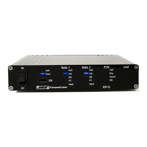
There is an LED audio level indicator on the panel that can be applied to any of the unit’s
channels; it aids setting and verifying proper volume settings.
Also on the RSP-Z2 front panel are:
•The power on/off switch.
•A USB port that can be used for JPS-specified USB wired and wireless headsets. See
Section 1.10 Optional Equipment: Not Supplied.
•Power and Fault LEDs.
•Indicator LEDs for each of the two analog channels: Fault, Link, COR, PTT, Signal.
All connections to the unit, other than the front USB port (for headset and USB thumb drive), are
made via the rear panel. This includes the RJ-45 Ethernet port, the +12 VDC power jack, a USB
jack (same functions as front panel USB port), an HDMI port, a D9 RS-232 port, and a pair of
D15 analog ports.
The two D15 analog ports conform to standard JPS radio ports, allowing them to use any of the
custom cables that JPS has designed to interface hundreds of different radio makes and models;
see the next section for further information.
Figure 2-2 RSP-Z2 Front and Rear Views

RSP-Z2 Operations Manual
RSP-Z2 Installation and Operation Manual 2-4 Interoperability Now
2.7 Radio Interface and Cables
The physical interfaces for the radio ports (and other four-wire devices) are a pair of rear panel
D-15 connectors. Radios are connected to the RSP-Z2 via a cable that is likely to include
interfacing circuitry (such as is used with JPS-manufactured radio cables).
The RSP-Z2 is designed to allow the use of the very large library of JPS radio cables created for
the ACU Gateway product line, including standard Military 5 and 6 pin microphone connectors.
These cables allow connection to hundreds of commonly deployed radios. See Table 1-3 –
Optional Equipment - Not Supplied.
Other cables can be designed and built on request. An unterminated cable can also be purchased;
this cable has bare wires on the radio end to allow a customer to create a cable. The JPS Customer
Service Department can be reached by phone at (919) 790-1011, or by email at
[email protected]. A representative will explain what is required. Typically, JPS Systems
Engineering will need a pair of operational radios and radio programming software to use while
creating and testing a new cable.
Table 2-1 Radio Connectors (Radio 1, Radio 2)
PIN
Signal
Description
1
Ground
Ground connection.
2
RXD
RX Data; used for special functions only.
3
/AUX Out 1
Auxiliary Output 1- Active low; used for special functions only.
4
/AUX In 1
Auxiliary Input 1- Active low; used for special functions only.
5
Ground
Ground connection.
6
TX Out B
Balanced transmit audio output.
7
Audio Ground
Audio ground connection for unbalanced inputs/outputs.
8
RX In A
Balanced receive audio input.
9
TXD
TX Data; used for special functions only.
10
/AUX Out 2
Auxiliary Output 2- Active low; used for special functions only.
11
/AUX In 2
Auxiliary Input 2- Active low; used for special functions only.
12
/PTT Out
Active low PTT output to a transmitter.
13
/COR In
COR input from a receiver, active low.
14
TX Out A
Balanced transmit audio output.
15
RX In B
Balanced receive audio input.
Note: For unbalanced TX audio, ground “B” pin of audio pair; connect unbalanced audio to “A” pin.
2.8 Power Source
The power supply included with the unit operates from input voltages and frequencies of 100 to
240 VAC, 50 - 60 Hz. Other standard “laptop-type” supplies can be substituted, but must provide
a nominal +12 VDC, and be capable of at least 1.5 amp output. Note that the power supply
included in the RSP-Z2 accessory kit is a premium version with a 1500V isolation transformer.
Other manuals for RSP-Z2
2
Table of contents
Other JPS Gateway manuals
Popular Gateway manuals by other brands

Packet8
Packet8 BPG510 Technical user guide

RTA
RTA 460MSBM-N700 Product user guide

ZyXEL Communications
ZyXEL Communications P-660HW-Tx v3 Series quick start guide

Alphatech
Alphatech BlueGate SIP 1 Installation and setup guide

2N
2N EasyGate Pro quick start

ZyXEL Communications
ZyXEL Communications P-660HNT1 quick start guide

Merak
Merak MMk-736 installation manual

BAB TECHNOLOGIE
BAB TECHNOLOGIE KNXEASY Documentation

Maretron
Maretron IPG100 Firmware recovery procedure

ZyXEL Communications
ZyXEL Communications VMG1312-T20A quick start guide

D-Link
D-Link DVG-1120S - VoIP Gateway/Router With 1 LAN... manual

ZyXEL Communications
ZyXEL Communications P-662HW-D - V3.40 quick start guide