Meanwell KDA-64 User manual

KDA-64 KNX to DALI Gateway
Instruction Manual

KDA-64 Instruction Manual
Content
1.Using the application program ..............................................................
.................................................................
............................................................
................................................................
.......................................................................
..............
....................................................................
..................................................
.............................................
...............
............................
...
...............................
..............................................................................
.....................................................................................
....................................................................................
..........................................................
................................
.....................................................
....................
1
1
1
1
3
8
20
31
34
31
32
34
36
22
25
26
27
9
5
6
2.General product information
2.1 DALI Bus system properties
2.2 KDA-64 product features
3.1 Installing the Plug-In
4.1 Commissioning with KDA-64 via web site or pushbuttons
6.1 Configuration buttons
7.1 Special functions in 'Normal Mode
7.2 Special functions in 'Extended Mode'
7.1.1 Synchronisation with the connected DALI segment
7.1.2 User-friendly names for ECGs and groups
7.2.1 Preparation and planning the DALI commissioning in 'Extended Mode
7.2.2 DALI commissioning in 'Extended Mode'
6.2 Control buttons
6.3 ECG fields
6.4 Group fields
6.5 Information and status fields
4.2 Commissioning with KDA-64 via ETS Plug-In
3.2 Principal structure of the Plug-In
3.3 Operating modes of the Plug-In: DALI commissioning
........
.............................................................................
...........................................................
........................................................................
...........................................
3
8
10
16
31
3.General properties of the ETS application program: KDA-64 Plug-In
4.DALI commissioning
5.Display and push-button control
6.Control via web browser
7.ETS Special and commissioning functions
Sep. 2017 Version 0

KDA-64 Instruction Manual
Content
....
................................
.................................................
.......................................
.............................................................
...........................................
..............................................
..........................
..................................................................................
..........................................................
......................................
........................................................
.......................................................
........................................................................
............................................................................
..............................................................................
.............................................................................
................................................................
......................
..................................................................................
...............................................................
39
40
41
41
42
38
43
44
45
49
49
50
51
52
45
46
47
47
47
48
49
7.2.4 Using dummy ECGs in 'Extended Mode'
7.3.1 Using IP for plug-in communication
7.3.2 Parameter templates
7.3.3 DALI configuration data back-up
7.3 General extra functions in the ETS
8.1. Quick exchange of individual ECGs
8.2 Extending the existing system – post-installation
9.1 Normal mode
10.1 Recording operating hours
10.2 Individual fault recognition at ECG level
10.3 Fault analysis at group level
10.4 Fault analysis at device level
11.1 The scene module
9.2 Permanent mode
9.3 Staircase mode
9.4 Night-time mode
9.5 Panic / emergency mode
9.6 Test mode for central battery emergency luminaires
9.7 Burn-in mode
9.8 Operating mode hierarchy
.......................................................
...................................................................
...........................................................
.............................................................................
43
45
49
52
8. DALI maintenance and expansion
9. Different operating modes
10. Analysis and service functions
11. Scenes and effects
7.2.3 ECG and lamp faults during DALI commissioning in 'Extended Mode'
....................... 52
11.1.1 Scene programming via the scene website

KDA-64 Instruction Manual
Content
..............
........................................................................
......................................................................................
....................................................
.............................................................
..................................................................................
................................................................................
.................................................................
...........................................
....................................................................................
.........................................
....................
...................................
............................................
..............................................
.................................
.............................
............................................
..............................
.............................
.............................
.........................................
...............
53
55
59
61
72
77
83
59
67
60
70
55
72
73
74
75
76
78
80
81
83
84
57
11.2 The effect module
12.1 Features
13.1 General communication objects
14.1 Device: General settings
14.2 ECG No. xx
14.3 Group No. xx
12.2 Converter inhibit mode
13.2 ECG-related communication objects
12.3 Test mode
13.3 Group-related communication objects
..........................................
...............................................
...................................................................
58
61
72
12. Self-contained battery emergency lamps
13. ETS communication objects overview
14. ETS parameter overview
11.1.2 Scene programming via ETS in 'Extended Mode
11.2.1 Effect programming using the effect website
14.1.1 Parameter page: General Settings
14.1.2 Parameter page: IP Settings
14.1.3 Parameter page: Behaviour
14.1.4 Parameter page: Special Functions
14.1.5 Parameter page: Analysis and Service
14.2.1 Parameter page ECG No. xx
14.2.2 Parameter page: Emergency Settings
14.2.3 Parameter page: Switching Behaviour
14.2.4 Parameter page: Analysis and Service
14.3.1 Parameter page: Group No. xx
11.2.2 Effect programming via ETS in 'Extended Mode'

KDA-64 Instruction Manual
Content
.............................
.............................
85
87
.............................................................
...........................................................
87
88
15. Firmware version and update
16. Reset to conditions at delivery
14.3.2 Parameter page: Switching Behaviour
14.3.3 Parameter page: Analysis and Service

1
1. Using the application program
Product family: Lighting
Product type: Gateway
Manufacturer: Mean Well
Name: KDA-64
2. General product information
2.1. DALI Bus system properties
The cross-functional DALI-Bus (DALI = Digital Addressable Lighting Interface) is a
system used to control electronic ballasts (ECGs) in lighting technology. The
specifications of the DALI communications interface are set in the international
norm IEC 60929.
The DALI Bus enables the receipt of switch and dim commands. In addition, the
DALI can be used for the notification of a fault status such as light or ECG failure or
for other light status information. In line with the latest DALI standard, devices with
emergency light function (EN 62386-202) are also supported. Status and operating
mode of emergency lights can be monitored and different prescribed testing
procedures can be performed.
Via the connected control device / gateway (Master), up to 64 individual DALI ECGs
(Slaves) can be connected in a DALI segment. When the DALI is commissioned, the
ECGs receive an automatically generated 3byte long address. Based on the long
address a short address between 0 and 63 is assigned during the further
commissioning process. As the address assignment is automatic, the device order
is random. The individual ECGs/lights therefore need to be identified during the
further commissioning process (see below).
The addressing of individual ECGs in the system is either based upon the short
address (individual addressing) or upon a DALI group address (group addressing).
For this purpose, any number of ECGs within a segment can be assigned to up to 16
groups. The group addressing in the DALI system guarantees that switch and dim
processes of different lights within a system are performed simultaneously without
imposition of time delays.
In addition to short and group addresses, the light values of individual DALI ECGs
can also be merged into scenes and addressed via scene addresses.
For a detailed description of the DALI system, please see the DALI handbook at
https://www.digitalilluminationinterface.org/
2.2. KDA-64 product features
The KDA-64 is a device used to control ECGs with a DALI interface via the KNX
installation bus. The device transforms switch and dim commands from the
connected KNX system into DALI telegrams and status information from the DALI
bus into KNX telegrams. The KDA-64 is a Category 1 device (in accordance with EN
62386-103). This means the device must only be used in DALI segments with

2
connected ECGs and not with other DALI control devices within the segment (no
multi-master function).
Power supply for the up to 64 connected ECGs comes directly from the KDA-64. An
additional DALI power supply is required and permitted.not not
The device comes in a 4TE wide DIN Rail casing so it can be directly integrated into
the mains distribution box.
In addition to the pure gateway functions, the
KDA-64 offers numerous additional features:
● Addressing of 16 DALI groups and/or individual addressing of up to 64 ECGs
● Flexible DALI commissioning concept: directly on the device or via the integrated
web server
● Different operating modes for groups and ECGs such as permanent mode, night-
time mode or staircase mode
● Burn-in mode for each individual light with specific burn-in time settings
● Integrated reader to count the operating hours of each light with an alarm to signify
the end of its life span
● Individual fault recognition with objects for each light/ECG
●Complex fault analysis at group and device level with number of faults and
calculation of fault rates
● Fault threshold monitoring with individually adjustable threshold values
● Scene module for extensive scene programming of groups and individual ECGs
● Effect module for sequence control and light effects
● “Quick exchange function“ for the quick and easy replacement of faulty ECGs
● Test mode for centrally powered emergency light systems
● Support of self contained emergency ballasts-

3
● Support of testing procedures for emergency lights with date and time stamp
●Integrated web server with extensive commissioning and maintenance
possibilities
● Integrated “visualisation“ via web-browser for direct control and display
3. General properties of the ETS application program: KDA-64
3.1 Installing the Plug-In
The application for the KDA-64 is based on a powerful KNX communications stack
of the System-B type. It is designed as plug-in for ETS-3 ETS-4, and ETS-5. The,
plug-in design means that an additional installation process is necessary. All
program files that are required are automatically set up when you import the
corresponding ETS product file (knxprod file).
After the import the product can be integrated as usual into the ETS. When you first
load the product in the ETS, you need to start the installation of the required plug-in
files by pressing the 'Next' button.
If it didn't pop-up pulg-in setup window during importing KDA-64.knxprod file, you
may find plug-in install as following example:
- Drag KDA-64 into the project e.g. Dining room
- Roll down dining room tab , find “1.1.1 KDA-64”
- Right click “1.1.1 KDA-64”, select “Plug-in” to install plug-in program.

4
And follow the instructions:
If the installation has been successful, a notification window appears.
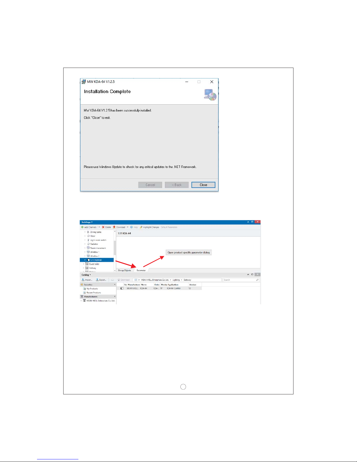
5
And, „open product specific parameter dialog“ is able to be used in parameter tab. If
plug-in didn't be installed properly, this function is not available. Later on we will
discuss more about parameter.
Attention: The PC must have .NET Version 4.0 as a requirement for the installation.
Normally the framework exists on any modern PC. Should an older version of .NET
be installed or no version at all, you need to update .NET first. Please see the
Microsoft website for the required setup.
3.2 Principal structure of the Plug-In
The KDA-64 is a high-functionality product and accordingly offers many different
setting options within the parameters. To make the overview of the parameters as
simple and transparent as possible for the system integrator, there are more
operating levels than with a standard ETS application.

6
Unlike with the standard applications, there is not only a parameter page for each
device within the main parameter directory on the left-hand side but also several
sub-pages which can be selected via a register at the top of the page. Use the main
directory to select the element you require “General ECG No XX, Group No XX“ and
the sub-pages to set the parameters of the selected element. This structure is
different from a standard device.
You can also use the three menus “Data, Tools and Help“ in the header of the plug-in
window to perform some of the main functions and settings.
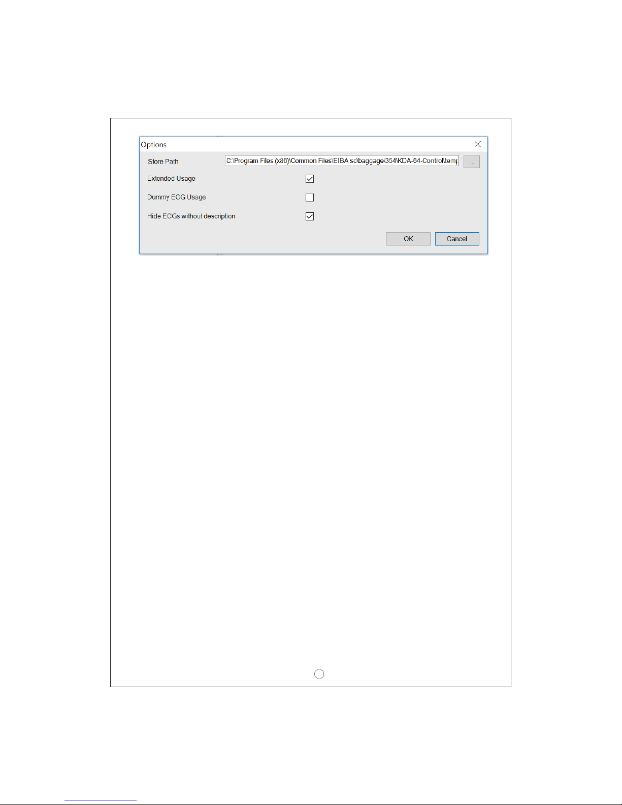
3.3 Operating modes of the Plug-In: DALI commissioning
In principle, the plug-in can be used in the two different operating modes “Normal
mode“ and “Extended mode“. Depending on the concept needed for the DALI
commissioning, you can select the required mode in the menu 'Tools' 'Options'.
7
The choice of the commissioning concept depends on the preferences of the system
integrator as well as the technical requirements of the project. If you choose option
A 'Normal Mode' the DALI configuration and commissioning must be performed via
the website of the device. This means that all project gateways - at least during the
commissioning phase - must be integrated into an IP network via the IP interface.
(The network can also be a simple cross-link cable connection between the gateway
and the configuration PC.)
If no IP network is available, only a limited commissioning process is possible via
the display and push-buttons on the device. However, if you choose commissioning
option B “Extended Mode“ the whole commissioning process can be performed via
ETS and KNX. No IP network is required in this case. Mode B also gives you the
opportunity to configure individual ECGs 'offline' in the ETS, i.e. before they are
commissioned in the installation. However, in this case all objects and parameters
are visible. The synchronisation that simplifies the ETS and brings it in line with the
actual system is not possible.
To decide which mode to use you should answer the following three questions:
`Is the DALI gateway (at least temporarily during the commissioning process)
integrated into an IP network?
oYes Mode A or mode B
oNo Mode B
`Do you want to set the DALI configuration and parameters 'offline' in the ETS
prior to the commissioning of the installation?
oYes Mode B
`Do you want to perform the DALI configuration and set the parameters on the
construction site and synchronise the ETS with the real installation to
simplify it?
oYes Mode A
Mode A: 'Normal Mode' --- Mode B: 'Extended Mode'
If the conditions permit it, we recommend using 'Normal Mode', especially for
integrators who are not too familiar with the DALI system because the large number
of possible parameter settings and objects can be automatically reduced to those
8
elements that are actually required. The standard setting after the initial installation
of the plug-in is therefore mode A.
Please remember that whichever operating mode you select, it applies to all
gateways within a project and ETS. It is not possible to select mode A for some and
mode B for others.
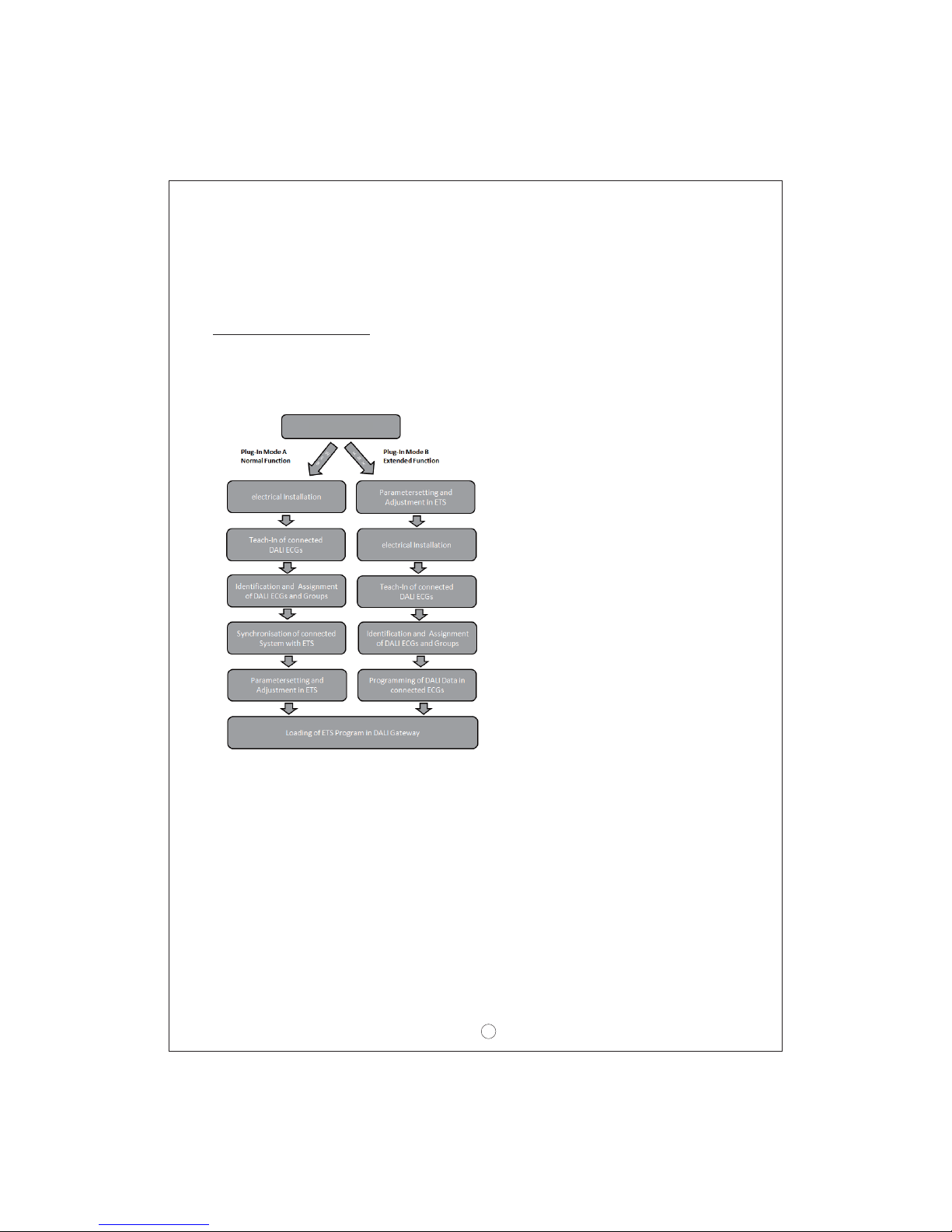
4. DALI commissioning
As explained above, the work flow for the commissioning of a DALI segment differs
depending on the selected concept. The following chart shows the general
4.1 Commissioning the KDA-64 via website or pushbuttons
If you select option A, i.e. commissioning the device via the website or pushbuttons,
please use the following procedure.
Following the physical installation and wiring of the ECGs and lights and the
electronic commissioning, the connected ECGs need to be taught-in. During the
teach-in process, all DALI ECGs are automatically recognised and each ECG is
assigned a short address between 0 and 63.
You can start this process either via the pushbuttons and menu on the device
display (see below display and push button control) or via the commissioning
website (see below control via web browser).
KDA-64 Plug-In

9
The order of the ECGs within a DALI segment is completely random. You therefore
need to identify the ECGs and - if required - assign them to groups. Identification
and group assignment can also be performed via the device itself (pushbuttons,
display) or via the website. If you use the website for identification, you can give
each ECG an individual name (e.g. office-left). If you want to control an ECG as part
of a DALI group rather than individually, you can at this point assign it to a group.
Once you have identified all ECGs and, if required, named and assigned them, you
need to synchronise the ETS application. During the synchronisation, the system
properties of the connected DALI segment are transferred to the ETS and the
parameters and communication objects are configured accordingly. This means that
after the synchronisation only objects and parameters of actually existing ECGs are
visible to the user. The application is thereby optimised and simplified. ECG and
group names are also transferred to the ETS. To start the synchronisation, press
the respective button on the ETS parameter page (see below ETS application
program).
Once the synchronisation is complete, you can configure the individual ECG or
group parameters in the ETS and connect communication objects with group
addresses.
When you have finished the configuration, simply download the ETS application
onto the device.
In principle, the installation is now ready for operation and function testing.
However, if you would also like to program scenes or effects, you can do so via the
pushbuttons and display on the device (only scenes and with limited functionality) or
via the web site (scenes and effects without limitation).
For a complete description of the display and push-button control required for the
commissioning, please see chapter 5. For a description of the website function,
please refer to chapter 6.
4.2 The commissioning process with KDA-64 via ETS Plug-In
Instead of commissioning via web browser or push-buttons, the DALI can also be
entirely commissioned via KNX and the plug-in. This mode B option enables a
largely 'off-line configuration' of the DALI installation. Parameters for ECGs and
groups as well as communication objects can be completely configured before the
electrical installation. Names can be assigned in advance and the setting of scenes
and effects is also possible 'offline'.
This means that the system integrator who uses the ETS and the electrician who
works on the actual installation can work independently of each other. Once the
electrical installation is complete, the actual DALI commissioning can also be
performed with ETS.
The first thing to do is to start the teach-in process. During this process all
connected DALI ECGs are automatically recognised and each ECG is assigned a

10
random short-address between 0 and 63. You can now identify the randomly
ordered ECGs/lamps by selecting a respective operation (on/off/blinking) in the
ETS. Use drag-and-drop to pull an ECG into the ECG position previously set in the
ETS. The random order is thus 'dissolved' and the installation is now well-
structured.
When you download the DALI configuration, the configured data is downloaded onto
the ECGs and if applicable the short-addresses are amended in line with the pre-
configuration. Once you have programmed all DALI data, load the actual ETS
application onto the gateway.
For a detailed description of the ETS commissioning interface, please see chapter
7.
5. Display and push button control
You can commission the connected DALI segment and set and change DALI
functions via the three pushbuttons (MOVE, Set/Prg, ESC) and the 2x12 character
display on the front of the device. The user concept is menu-based. Depending on
the menu position, you can select two sub-levels. The current menu position is
shown on the display. To navigate within the menu, press the pushbuttons briefly.
Use the Move button to select the next menu item on the same level. Use the
Prg/Set button to go to the next lower level. Press the ESC button to leave a level
and return to the next higher level.
Main menu– Level 1
The main menu (Level 1) has the following structure:
The product name and rmware version are displayed. The sub-menu
can be used to set the display language.
The sub-menu displays the IP address set in the ETS or assigned
by he DHCP server.t
When a DALI segment is newly the sub-menu to resetinstalled, use
the connected DALI devices and automatically search for ECGs.
Use the sub-menu to start the automatic search process and possibly
adjust the configuration following a post-installation of DALI ECGs.
Use the sub-menu to active the ECG quick exchange function and
possibly program and integrate individually replaced ECGs into the
system.
POST
INSTALLATION
ECG EASY
REPLACEMENT
NETWORK
IP ADDRESS
DALI CONTROL
- V1.2
NEW
INSTALLATION

11
Use the sub-menu to identify ECGs and assign them to DALI groups.
Use the sub-menu to assign groups to DALI scenes
Use the sub-menu to switch both the whole installation (broadcast) and
individual channels for test purposes.
GROUP
ASSIGNMENT
SCENE
ASSIGNMENT
GROUP
TEST
Use the sub-menu to test individual scenes.
Use the sub-menu to load any existing system faults.
Use the sub-menu to start the burn-in mode for ECGs and to re-set
operating hours.
Use the sub-menu to activate the converter inhibit mode in the
installation phase.
MAINTANANCE
ECG/LAMP
CONVERTER
INHIBIT MODE
TEST
SCENES
SYSTEM
TEST
To perform a function or change a configuration within a sub-menu, go to the
respective position and change into programming mode. To change into
programming mode, hold the Prg/Set button for more than 2 seconds. Once the
function is in programming mode, a symbol appears in the display. If the
programming mode is active, use the Move button to change a parameter or setting.
Briefly press the Prg/Set button again to complete the process and save the set
parameter or activate the function.
Sub-menu DALI CONTROL – Level 2
The currently set display language is shown. Hold the Prg/Set button to
change into programming mode. Use the MOVE button to choose from
one of the following languages: GERMAN, ENGLISH, FRENCH,
SPANISH, ITALIAN, DUTCH, SWEDISH, DANISH. Briefly press the
Prg/Set button again to save the configuration. The display now works
in the selected language.
Briey press the Prg/Set button to change from the main menu DALI
CONTROL to the sub-menu LANGUAGE.
DALI CONTROL
- V1.2
LANGUAGE
GERMAN

12
Briefly press the Prg/Set button to change from the main menu IP
ADDRESS to the sub-menu.
Briefly press the Prg/Set button to change from the main menu NEW
INSTALLATION to the sub-menu SEARCH ECGs via PROG-MODE.
The sub-menu displays the IP address currently set in the ETS or
assigned by the DHCP-Server.
Hold the Prg/Set button to change into programming mode. Briefly
press the Prg/Set-button again to start the initialisation and search
process. First, all ECGs connected to the DALI segment are
automatically reset and any previously set parameters and group
assignments are deleted. The device then searches for the connected
ECGs via their random long address. The ECGs are automatically
recognised in ascending order. Depending on the number of connected
ECGs the search process may take a few minutes. Once the process is
complete, the number of ECGs found is shown on the display. Press
the ESC button (or wait for about 30 seconds) to return to the level
above.
Sub-menu NETWORK IP_ADDRESS – Level 2 and 3
Sub-menu NEW INSTALLATION – Level 2
NETWORK
NEW-
INSTALLATION
DHCP: 192.
168.010.134
SEARCH ECGs
via PROG
MODE
FOUND
ECGs: 47
IP ADDRESS
Briefly press the Prg/Set button to change from the main menu POST-
INSTALLATION to the sub-menu SEARCH ECGs via PROG-MODE.
Hold the Prg/Set button to change into programming mode. Briefly
press the Prg/Set-button again to start the verification and search
process. The device searches for the connected ECGs via their long
address and automatically compares them to the previous
configuration
If ECGs have been removed from the DALI segment, the entries are
deleted from the device. The number of deleted devices is displayed
during the verification process.
After that, the DALI segment is searched for newly installed devices.
Newly added ECGs are automatically reset and any previously
programmed parameters and group assignments are deleted.
Depending on the number of connected ECGs the search process may
take a few minutes. During the search process, the number of newly
found devices is shown on the display.
Sub-menu POST-INSTALLATION – Level 2
POST
INSTALLATION
SEARCH ECGs
via PROG-MODE
DELETED
ECGs: 3
NEW
ECGs: 1

13
Once the whole process (verification and search) is complete, the
display shows both the deleted and the newly found ECGs (deleted
devices / new devices from left to right, see picture on the left). Press
the ESC button (or wait for about 30 seconds) to return to the level
above.
Briefly press the Prg/Set button to change from the main menu ECG
QUICK EXCHANGE to the sub-menu SEARCH ECGs via PROG-
MODE.
Briefly press the Prg/Set button to change from the main menu GROUP
ASSIGNMENT to the sub-menu.
Within this menu the individual ECGS that were found during the
search process can be assigned to 16 DALI groups and previous
assignments can be modified.
Briefly press the MOVE button to run through the different ECGs. The
number of the selected ECG is shown in the first display line. As long
as the ECG is selected, the connected lamp is flashing. The
programmer can thereby determine which lamp is assigned to the
number.
If the selected device is a non-switchable converter for emergency
lights, the selection sets the device into function test mode and the
display shows the word CONV. For identification purposes, the
function LED on the converter flashes during the test (see user manual
for the converter).
Hold the Prg/Set button to change into programming mode. Briefly
press the Prg/Set-button again to start the quick exchange The.
device first checks if one or several ECGs in the system were faulty. It
then automatically looks for newly connected ECGs in the segment.
The quick exchange is only possible if just one ECG in the segment
was faulty and one new ECG is found. If the process is successful, the
number of the replaced ECG is shown. If the search process cannot be
completed because the required conditions are not met, an error code
appears in the display. The error codes have the following meaning:
Error Type 7: No ECG failure
Error Type 8: More than one ECG failure
Error Type 9: No new ECG can be found
Error Type 10: ECG has wrong device type
Error Type 11: More than one new ECG
Press the ESC button (or wait for about 30 seconds) to return to the
level above.
Sub-menu ECG QUICK EXCHANGE – Level 2
Sub-menu GROUP ASSIGNMENT – Level 2 and 3
DEL./NEW
ECGs: 3/1
ECG QUICK
EXCHANGE
GROUP
ASSIGNMENT
ECG No.: 12
GROUP: --
CONV. No.: 13
GROUP: --
SEARCH ECGs
via PROG-MODE
ECG 04
REPLACED
ERROR
TYPE 07

14
Hold the Prg/Set button to change into programming mode. Briefly
press the MOVE button again to select the group that you want to
assign the ECG to. If the group is selected, briefly press the Prg/Set
button to confirm and save the setting. You must repeat this process
once for every ECG during the initial installation. Attention: non-
switchable converters for emergency lights cannot be assigned to a
group.
Press the ESC button (or wait for about 30 seconds) to return to the
level above.
Briefly press the Prg/Set button to change from the main menu SCENE
ASSIGNMENT to the sub-menu. Within the menu the DALI groups can
be assigned to up to 16 possible scenes. Individually controlled ECGs
cannot be assigned via the display. To assign individual ECGs, you
must use the website.
Briefly press the Prg/Set button to change from the main menu GROUP
TEST to the sub-menu. Within the menu, groups can be switched
either individually or all together (ALL GROUPS TEST) to test the
installation.
Briefly press the MOVE button to run through the individual scenes.
The number of the selected scene is shown in the first display line.
Behind the scene number, different characters show which of the 16
groups are assigned to the scene. An X means that a group is
assigned to the scene. A – means the group is not assigned to the
scene. The four characters directly behind the scene number in the
first display line represent groups 1 - 4 (from left to right). The 12
characters in the second display line represent groups 5 – 16 (from left
to right).
Hold the Prg/Set button to change into programming mode. A flashing
cursor on the first X means that group 1 is selected. By briefly pressing
the Move button you can toggle between X and – symbols to choose
whether you would like to assign the group to the scene. Briefly press
the Prg/Set-button to move the cursor to the next group. Once you
have run through all 16 groups, the setting is saved and used during
further scene programming. After you have pressed the Prg/Set button
a final time, the display automatically returns to the level above. Press
the ESC button to return to the level above without saving the changes
you have made.
Sub-menu SCENE ASSIGNMENT – Level 2 and 3
Sub-menu GROUP TEST – Level 2 and 3
ECG No.: 12
GROUP: 1
SCENE
ASSIGNMENT
GROUP
TEST
SCENE01 XXXX
XXXXXXXXXXXX
SCENE03 ----
XXXX------XX

15
Briefly press the MOVE button to run through the individual groups.
The number of the selected group is shown in the first display line.
Hold the Prg/Set button to change into programming mode. Briefly
press the Move button to select whether you would like to switch the
group on or off. Briefly press the Prg/Set button to execute the selected
command. Press the ESC button (or wait for about 30 seconds) to
return to the level above.
GROUP: 6
TEST
GROUP: 6
->off
Briefly press the Prg/Set button to change from the main menu SCENE
TEST to the sub-menu. Within the menu you can invoke all scenes for
test purposes or program newly set light scenarios into the scene.
Briefly press the Prg/Set button to change from the main menu
SYSTEM TEST to the sub-menu. Within the menu you can check for
any potential faults.
If there has been a DALI short-circuit, no further faults can be recognised. For
all other fault types, several faults can be recognised at the same time. Within
the menu you can toggle between the different faults by briefly pressing the
Move button. The number of the ECG is displayed for both lamp and ECG
faults. This means that a fault can be easily localised. Press the ESC button
(or wait for about 30 seconds) to return to the level above.
If there is no fault, this is shown in the display. The following faults can
be recognised by the system. They are shown in the display and also
simultaneously set off the red error LED:
● DALI short-circuit
● Lamp fault with the lamp or ECG number being displaye
●ECG fault with the ECG number being displayed
●No KNX bus
Briefly press the MOVE button to run through the individual scenes. The
number of the selected scene is shown in the first display line.
Hold the Prg/Set button to change into programming mode. Briefly
press the Move button to choose whether you would like to invoke or
save a scene. Briefly press the Prg/Set-Taste button to execute the
selected command and either invoke or save the scene. Press the ESC
button (or wait for about 30 seconds) to return to the level above.
Sub-menu SCENE TEST – Level 2 and 3
Sub-menu SYSTEM TEST – Level 2 and 3
SCENE
TEST
SYSTEM
TEST
LAMP 17
Fault
DALI
No fault
ECG 34
Fault
DALI
Fault
KNX
No Fault
SCENE: 2
TEST
SCENE: 2
->invoke
Table of contents
Other Meanwell Gateway manuals


