Step 3: On the amplifier, locatethe SV (Servo) receptacle. Plug the rudder servo into
thisreceptacle, noting the correct polarity as indicated by the shape of the plug, as
well as the wire color.
Tail Lock™ Selection/Connection
The G5000T offers several methods to access and use the tail lock function.
Note: If you’re using a 6- or 7-channel system, you must install theG5000T as
detailed in Option 1.
Option 1: Tail Lock Mode or Rate Mode Always On
If you choose to havethe G5000T function in either tail lock or late mode only,
simplymove the tail lock switch located on the amplifier to the desired position(On
for tail lock, OFF for rate mode). With this option, it is not necessary to connect the
black SEL Aux 2 connector. Please note that with this method, it is not possibleto
access both the tail lock and rate modes as only one Aux channel is being used.
Quick Start
Option 1 is a quick way to get up and flying with your G5000T, as it’s the easiest
to set up. If you select the option to have the tail lockmode on, it will not be neces-
sary to use any form of tail rotor compensation, further simplifying the initial setup.
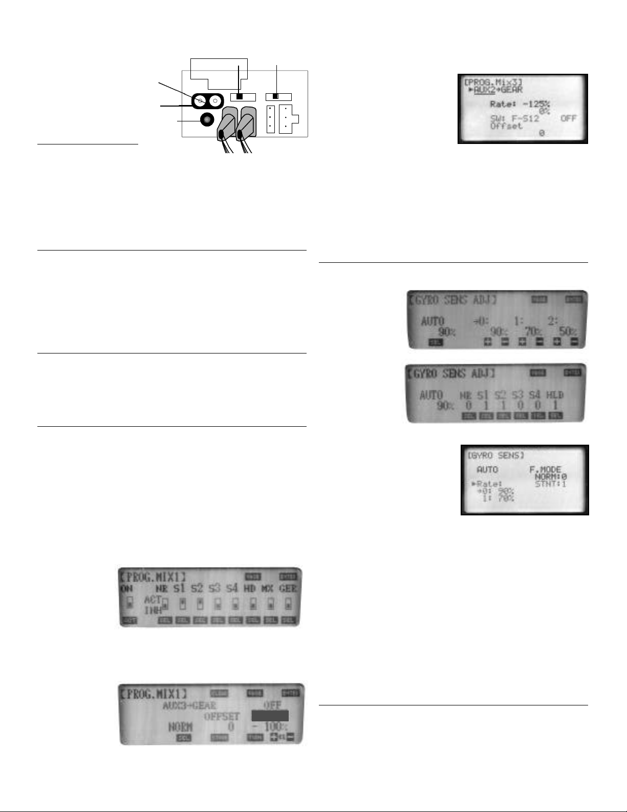
Option 2: Remote Rate and Tail Lock Mode Access
Connect the black SEL Aux 2 connector from the amplifier to the following chan-
nel on your receiver:
JR PCM 10 series (9- and 10-channel systems): Gear (Channel 5)
JR XP8103 series (8-channel systems): Gear (Channel 5)
This option will allow both thestandard rate and tail lock modes of the G5000T to
be remotely selected during flight via the gear switch.
This method will also allow for the use of an optional program mix that will allow
the G5000T’s modes to be selected via the Aux 3 gyro gain function. This method
will also enable the G5000T’s modes to be linked to the flight mode switch.
INITIAL RADIO SETUP
The G5000T Gyro is much more responsive than a standard piezo gyro, and it
can sense and correct for rotation rates at over 720˚ per second (standard gyros are
limited to approximately 250˚ per second). Because of this, the travel adjust and
exponential values can be much different than they are with other gyros to obtain the
optimum feel and rotation rates.
Travel Adjust
Set the rudder’s travel adjustment to maximum right and left. If you’re using a JR
PCM-10/10S/10SX, set the travel adjustment to 150% left and 150% right.
Dual Rates
The recommended starting points for dual rates are:
Flight Mode Maneuver Dual Rate Value
Normal Hovering 60%
Flight Mode 1 540 stall turns 100%
Flight Mode 2 Standard aerobatics 60%
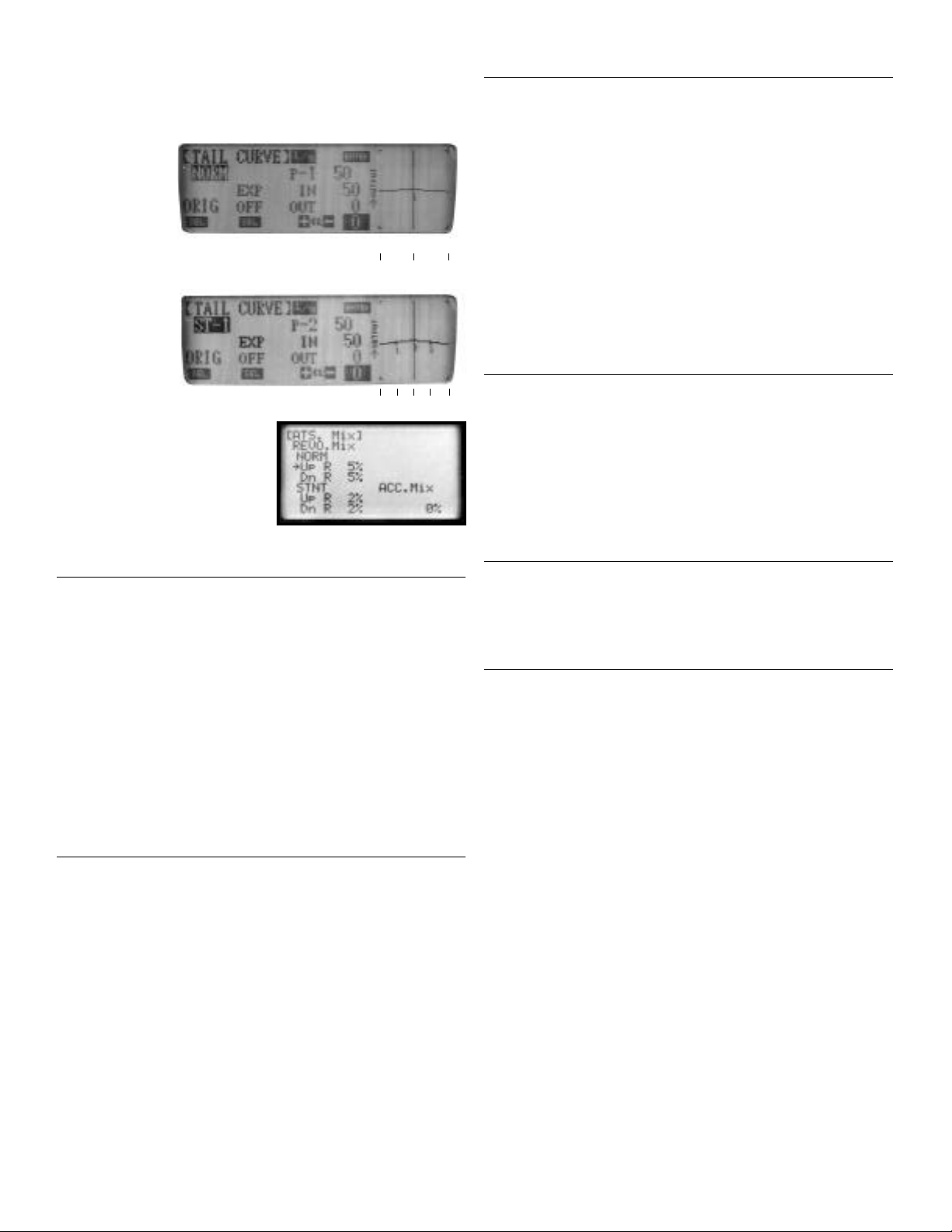
Exponential
Because a very large stroke isused (150%), the control sensitivity around neutral
is high. Exponential is necessary to reduce the sensitivity around neutral. The rec-
ommended starting points of exponential are:
Flight Mode Maneuver Exponential Value
Normal Hovering 60%
Normal Hovering 40%
Flight Mode 1 540 stallturns 60%
Flight Mode 2 Standard aerobatics 60%
Note: After you have gained some experience and flight time, you can alter travel
adjust, dual rate, and exponential values to suit your flying style.
SETUP AND ADJUSTMENT
The G5000T Piezo gyro gives true linear feedback response of rotation rates from
as little as 1˚ per minute up to over 720˚ per second. Because of its high response
rate and authority, the adjustment values (e.g., travel adjust, exponential, tail rotor
compensation, etc.) will be very different from what you’re used to.
Following is the step-by-step procedure that must befollowed to achieve the
highest level of performance from your gyro system.
Step 1: Unhook the tail rotor linkage at the rudder servo and swing the servo arm
out of the way. Lightly grasp the tail rotor pushrod at the servo end and move the
tail rotor throughout its entire stroke. The tail rotor linkage should move through
its full range smoothly with very little friction and no rough spots. Work on the
linkage system until this is achieved.
Step 2: On your transmitter, reset all the rudder trimmers (sub-trim, trim offset,
stunt trim, mechanical trim lever, etc.) to zero or center. Set the throttle/pitch stick
at exactly the hover position (normally 50%). Turn off or zero out both the revolu-
tion mixing (up and down) and the acceleration mixing.
Step 3: Turn on your receiver and allow the helicopter to remain totally motionless
for three seconds. A bright LED light on the amplifier will come on after three sec-
onds, indicating the gyro has digitally stored the zero rotation value.
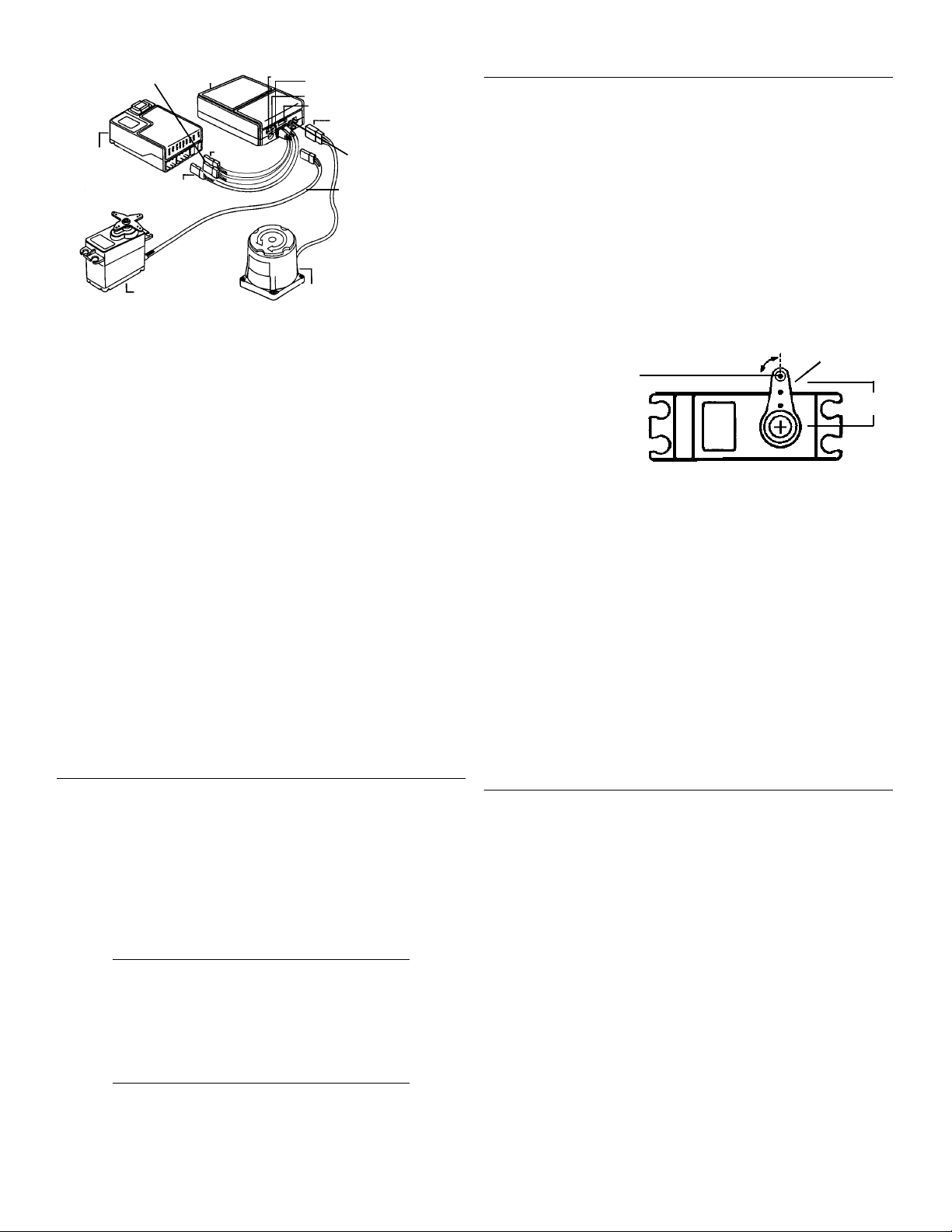
Step 4: Install the servo arm
90˚ to the tail rotor pushrod
(see diagram). You may find
that the splines are slightly
offset on your servo, not
allowing an exact 90˚ position-
ing. If so, rotate the servo arm
to another arm position and
try again. Secure the arm in
place with the screw provided.
Attach the pushrod to the arm
at approximately 16 mm out
from the center. Later, we will
optimize this distance through flight testing.
Step 5: Be sure the rudder servo is moving in the correct direction. A right servo
command should move the nose of the helicopter to the right. (If you’re unsure,
seek help from someone with more experience.) Reverse the servo direction in the
transmitter’s programming if necessary.
Step 6: Give a right rudder command and note the direction the rudder servo
moves (clockwise or counterclockwise). Then pick up the helicopter and quickly
rotate the nose to the left. The servo should move in the same direction as it did
when you applied right rudder (clockwise or counterclockwise). If the rudder servo
rotates in the opposite direction, move the reverse switch located on the amplifier
in the opposite direction.
Step 7: With the G5000T in tail lock mode (green LED), check to insure that the
servo will remain in the neutral (centered) position. If the servo “Drifts” or slowly
moves in either direction, enter the sub trim function of your radio system and add
a sub trim value as needed until the servo will remain in the neutral position, with
no tendency to drift in either direction.
TAIL ROTOR LINKAGE ADJUSTMENT
With theservo arm positioned at 90° degrees to the control rod, adjust the over-
all length of the tail control rod so that the tail pitch mechanism is at the center of its
travel limits. It’s also necessary to insure that the tail rotor blades have the proper
degree of pitch in the neutral position to maintain a stationary hover. Approximately
5° is agood starting point. The final pitch of the tailblades will need to be fine tuned
during test flights byadjusting the tail linkage mechanically.
Adjusting the Endpoint Limiters
With the travel adjust set to 150%, you will notice that moving the rudder stick to
its extremes may bind (over-stroke) the tail rotor linkage. JR’s G5000T has a unique
feature that electronically limits the maximum servo travel, preventing binding/over-
stroking of the rudder linkage — but it has no effect on the maximum control
authority during high speed pirouettes.
Note: Locate the tail lock switch on the G5000T amplifier, and move the switch to
the OFF position. This will allow for proper servo end point travel adjustment. Reset
the switch to the desired position once the endpoint limiter has been adjusted.
With your radio system on, give a full right ruddercommand. Using a small
straight screwdriver, adjust theservo travel limiter while noticing the rudder servo.
Adjust the pot until the servo has maximum available travel but no binding occurs.
Give a fullleft rudder command and adjust the limiter as needed to the point just
before the servo binds. This sets the maximum available travel and eliminates link-
age binding/over-stroking while the helicopter is on the ground.
Note: You will notice that with the travel limiters adjusted, it appears that the rud-
der stick only works the servo throughout half its stroke. This is normal! During
flight, the gyro provides feedback to the servo that combines information about its
rotation rate and the gain setting that gives proportional rotation rates throughout
the rudder’s stick travel.
Gyro Amp Travel Limiter
LED Red/Green
Tail Lock On/Off
Connector
to Gyro Sensor
Rev. Switch
Servo
Connector
Connect to
SV
Gyro Sensor
JR 8700G Super Servo
or 8417 Digital Servo
Rudder Connector
Connect to RUDD
SELRate/Tail Lock
Remote Select
Aux 3 Connector
(white)
Receiver
Rudder Servo
90°
16 mm
Control Ball
Attach Contr
o
Ball to Arm
16 mm from
Center
Tail Lock Sensitivity Adj.