JUKI LK-1900A Quick start guide

40014262
No.E357-00
ENGINEER’S MANUAL
Computer-controlled High Speed
Bar Tacking Industrial Sewing Machine
LK-1900A Series
®

PREFACE
This Engineer’s Manual is written for the technical personnel who are responsible for the service and maintenance
of the machine.
The Instruction Manual for these machines intended for the maintenance personnel and operators at an apparel
factory contains operating instructions in detail. And this manual describes “StandardAdjustment”,Adjustment Pro-
cedures”, “Results of ImproperAdjustment”, and other important information which are not covered in the Instruction
Manual.
It is advisable to use the relevant Instruction Manual and Parts List together with this Engineer’s Manual when
carrying out the maintenance of these machines.
This manual gives the “Standard Adjustment” on the former page under which the most basic adjustment value is
described and on the latter page the “Results of Improper Adjustment” under which stitching errors and troubles
arising from mechanical failures and “How To Adjust” are described.

CONTENTS
1. Specifications ......................................................................................................... 1
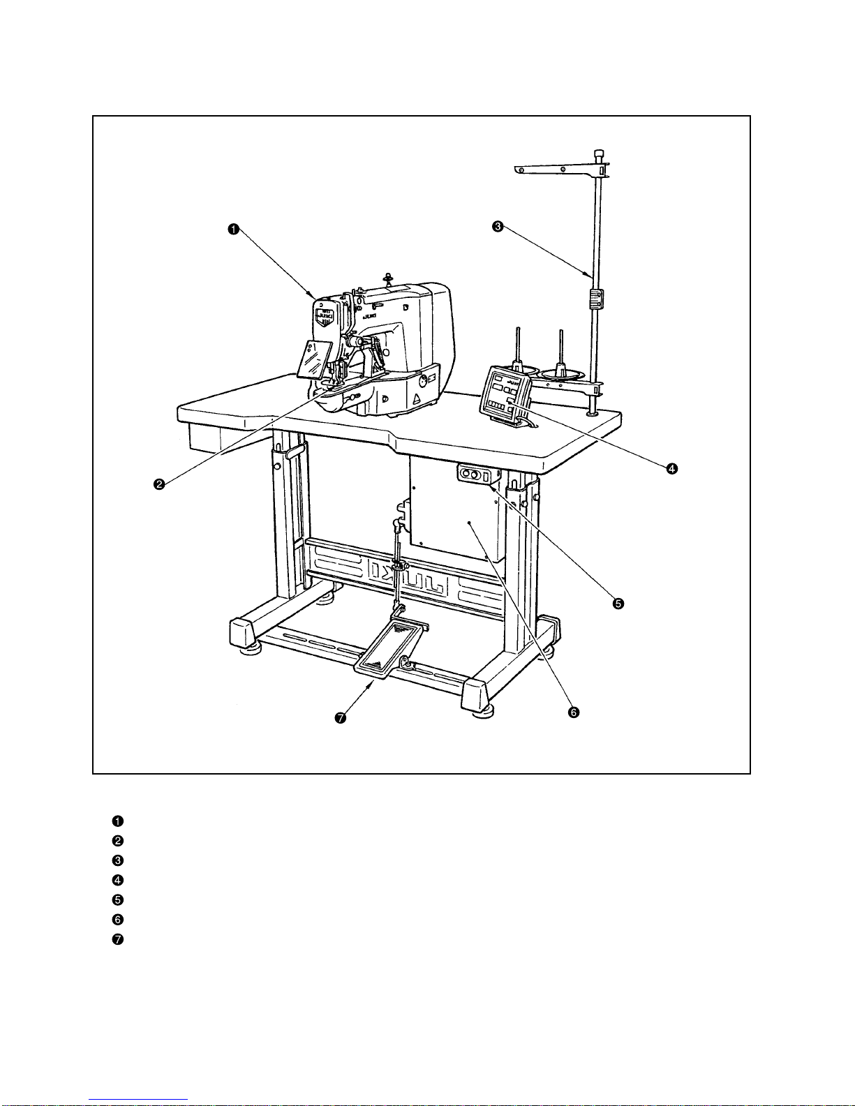
2. Configuration........................................................................................................... 2
(1) Names of main unit ................................................................................................................... 2
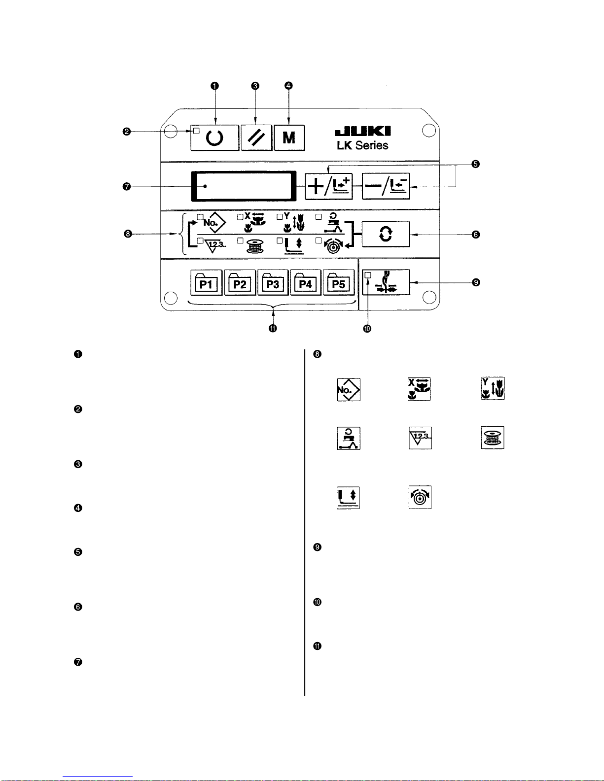
(2) Names and explanation of switches on the operation panel................................................ 3
3. Standard adjustment ..............................................................................................4
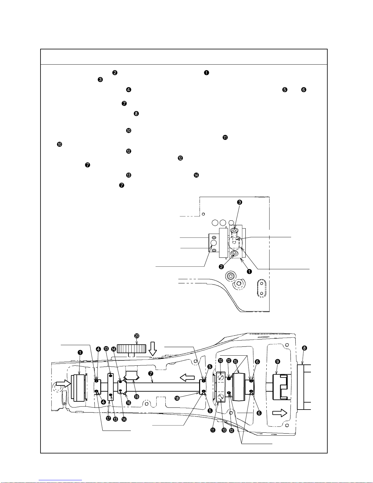
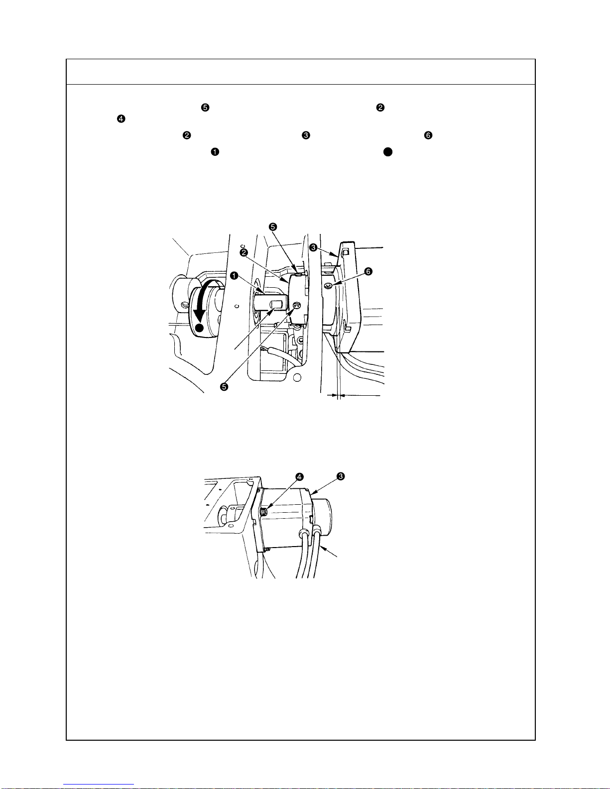
(1) Main shaft connection/disconnection..................................................................................... 4
(2) Removal of the main shaft motor and coupling..................................................................... 6
(3) Crank connecting rod connection / disconnection ............................................................... 8
(4) Crank balancer positioning.................................................................................................... 10
(5) Lower shaft backlash adjustment and connection/disconnection .................................... 10
(6) Oscillator gear positioning..................................................................................................... 12
(7) Adjustment of hook oil amount ............................................................................................. 12
(8) Large hook connection / disconnection and oil wick piping .............................................. 14
(9) Adjusting the height of the needle bar.................................................................................. 14
(10) Hook adjustment ................................................................................................................... 16
(11) Thread trimmer cam position adjustment and connection / disconnection ................... 18
(12) Thread trimmer and presser foot origin sensor adjustment............................................. 18
(13) Adjusting the lift of the work clamp foot ............................................................................ 20
(14) Adjusting the thread trimmer sensor .................................................................................. 20
(15) Adjustment of the moving knife and counter knife position ............................................ 22
(16) Adjusting the height of the moving knife and counter knife ............................................ 22
(17) Inclination of the blade point of the counter knife............................................................. 24
(18) Floating amount of the thread tension disk ....................................................................... 24
(19) Second thread tension connection / disconnection.......................................................... 26
(20) AT unit connection / disconnection .................................................................................... 28
(21) Position of the mechanical origin........................................................................................ 30
(22) Adjusting the Y origin sensor ..............................................................................................30
(23) Adjusting the X origin sensor ..............................................................................................32
(24) Adjusting the wiper position................................................................................................ 32
(25) Adjusting the wiper spring (LK-1903A only) ...................................................................... 34
(26) Adjusting the position of the X feed motor and the Y feed motor
(Adjusting the backlash of the driving gear)..................................................................... 34
(27) Installing the feed plate support plate ................................................................................ 36
(28) Installation of the feeder bar rear cover.............................................................................. 36
(29) Adjustment of the bobbin winder driving wheel position ................................................. 38
(30) Adjusting the bobbin winder amount.................................................................................. 38
(31) Adjustment of the hook upper spring position .................................................................. 40
(32) Shuttle felt.............................................................................................................................. 40
(33) Shape of the shuttle race ring.............................................................................................. 42
(34) Adjustment of the thread take-up spring............................................................................ 42
(35) Needle thread clamp device connection / diconnection ................................................... 44
(36) Adjusting the needle thread clamp sensor......................................................................... 46
(37) Adjusting the needle thread clamp notch........................................................................... 48
4. Sub-class information .......................................................................................... 50
(1) Models classified by button sizes (LK-1903A) ..................................................................... 50
(2) Table of Standard Patterns (LK-1903A)................................................................................. 51

5. Memory switches .................................................................................................. 52
(1) Memory switch start and change .......................................................................................... 52
(2) Table of memory switch functions ........................................................................................ 53
6. Test mode .............................................................................................................. 57
(1) Test mode start........................................................................................................................ 57
(2) Display output test.................................................................................................................. 58
(3) Method of confirmation according to each test program No. ............................................ 59
7. Miscellaneous........................................................................................................ 64
(1) Various printed wiring boards ...............................................................................................64
(2) LK1900 data ROM.................................................................................................................... 71
(3) Dipswitch setting .................................................................................................................... 71
(4) Table of standard pattern specifications .............................................................................. 72
(5) Table of standard patterns ..................................................................................................... 73
8. Optional features................................................................................................... 75
(1) Connection of PK-57............................................................................................................... 75
(2) Table of optional parts............................................................................................................ 76
(3) Table of the work clamp foot.................................................................................................. 78
9. Maintenance .......................................................................................................... 80
(1) Replacing the fuse .................................................................................................................. 80
(2) 100V ↔↔
↔↔
↔200V voltage specification changeover.................................................................. 80
(3) Greasing parts......................................................................................................................... 81
(4) Parts to which grease is applied ........................................................................................... 82
(5) Grease-up procedures for the specified position................................................................ 89
10. Table of errors ..................................................................................................... 90
11. Troubles and corrective measures .................................................................... 93
(1) Mechanical parts ..................................................................................................................... 93
(2) Sewing conditions .................................................................................................................. 95
(3) Electrical components.......................................................................................................... 103
12. Circuit diagrams.................................................................................................111
(1) Block diagram A .....................................................................................................................111
(2) Power supply circuit diagram A........................................................................................... 112
(3) Power supply circuit diagram B .......................................................................................... 113
(4) Power supply circuit diagram C .......................................................................................... 114
(5) Servo motor circuit diagram ................................................................................................ 115
(6) Sensor – pedal VR circuit diagram...................................................................................... 116
(7) MAIN • PANEL board circuit diagram .................................................................................. 117
(8) Motor • solenoid circuit diagram ......................................................................................... 118
13. Table drawings .................................................................................................. 119
(1) Table type for longitudinal Installation ............................................................................... 119
(2) Table type for lateral Installation ......................................................................................... 120

– 1 –
1. Specifications
No. Application
LK-1900A LK-1901A LK-1902A LK-1903A
1 Application Bartacking
Eyelet buttonhole bartacking
Belt-loop attaching
Lock stitch button sewing
2 Sewing area
X-Direction (right, left) 40mm; Y-Direction (forward, backward) 30mm
3 Button size Type: Round-shaped, flat button
ø 8 to ø32mm, Standard (ø8 to ø20mm)
4 Max. sewing * 3000rpm max. * 3000rpm max. * 2700rpm max.
speed
5 Stitch length 0.1mm to 10.0mm (adjustable in 0.1mm step)
6
Feed motion of work clamp foot
intermittent feed (2-shaft drive by stepping motor)
7 Meddle bar stroke 41.2mm 45.7mm
8 Needle DPX5 #14 DPX17 #14
DPX5#11 (F, M) (DPX17#21
(DPX17#21 heavy-weight material)
heavy-weight material)
9 Work clamp lifting Pulse motor
system
10 Lifting (lift) amount Standard 14mm, Max.17mm (In the reverse-rotation needle-up Max. 13mm
of work-clamp foot function)
11 Number of standard 50 patterns 3 patterns 6 patterns 50 patterns
patterns
12 Wiper system Interlockly with work clamp foot lifter by pulse motor
13 Needle thread Standard: General 0 Standard: Disable 1
clamp device (Caution) 1.
14
Needle thread tension
Active tension (electronic thread tension control mechanism)
15 Hook
Standard semi-rotary hook
(2-fold semi-rotary hook)
16 Lubrication Hook : minute-quantity lubrication
17 Lubricating oil JUKI NEW Defrix oil (equivalent to ISO VG32) (Lubrication system)
18 Grease 1. Penetration No. 2 lithium grease, 2. Templex N2, 3. Juki Grease A, 4. Juki Grease B (Caution)2.
19 Memory medium EEP-ROM (128Kbyte) EP-ROM (32Kbyte)
20
Number of stitches that
Max. 20,000 stitches
can be stored in memory
21 Enlarging/Reducing X-Direction, Y-Direction: 20 ~ 200% each (1% step)
facility
22
Enlarging/Reducing method
Pattern enlargement/reduction can be done by increasing/decreasing the stitch length
23
Sewing speed limits 450 ~ 3000rpm (100rpm step) (2700rpm max. for the 2-fold semi-rotary hook)
400 ~ 2700rpm (100rpm step)
24
Material clrawing amount
Max. 3mm
25
Pattern selector facility
Pattern No. designation system (1 ~ 200)
26
Bobbin thread counter
Up/Down method (0~9999)
27
Sewing machine motor
450W compact AC servomotor (direct-drive system)
28
External dimensions
W: 1200mm, L: 660mm, H: 1100mm (standard table stand applied)
29 Weight Machine head (include motor): 42kg, Control box: 16.5kg
30
Power consumption
320W
31
Working temperature range
5°C~35°C
32
Working humidity range
35% ~ 85% (no dew condensation permissible)
* Maximum sewing speed should be reduced according to the sewing conditions.
(Caution) 1. LK-1903A is set to needle thread clamp prohibited (no motion) with memory switch No. 35 at
the time of standard delivery.
2. Grease type, refer to (3) Greasing parts of [9] Maintenance.
Model name
Item
(When sewing pitches are less than 5mm in
X-direction and 3.5mm in Y-direction)
(*2700rpm fo the
2-fold semi-rotary hook)

– 2 –
2. Configuration
(1) Names of main unit
Sewing machine head
Work clamp foot
Thread stand
Operation panel
Power switch
Control box
Pedal switch

– 3 –
Item selection LED
LEDs of the selected items light up.
Needle thread clamp ON/OFF key
This key selects effective/ineffective of needle thread
clamp. When it is effective, needle thread clamp
disply LED lights up. (Note) 1.
Needle thread clamp display LED
When this LED lights up, needle threas clamp
operaters.
Pattern registration key
This key registers the pattern. When this key is
pressed, the pattern registered here can sew imme-
diately.
X/Y scale, sewing position, ets. can be changed and
registered.
Pattern No. X scale Y scale
Max. speed Sewing counter Bobbin winder
limitation
Work clamp foot Thread tension
lowering
(2) Names and explanation of switches on the operation panel
“Ready” key
Thiskeychangesoverthesettingstatefrom the panel
to the sewing state where the sewing machine actu-
ally operates.
Sewing LED
This LED goes off at the time of setting state and
lights up at the time of sewing state. Changeover
can be performed with “Ready” key.
“Reset” key
This key is used for canceling error or returning the
set value to the initial value.
“Mode” key
This key makes the setting mode of the memory
switch.
“+ / Feed forward” key, and “- / Feed backward”
key
This key is used for changing pattern No. and X/Y
scale, and feed forward/feed backward.
“Selection” key
This key selects the item to be set. Item selection
LED of the selected item and the set value are dis-
played.
Data indication LED
This LED indicates the set values of the selected
items such as pattern No., X/Y scale, etc.
(Note) 1. LK-1903A is set to needle thread clamp prohibited (no motion) with memory switch No. 35 at the
time of standard delivery.

– 4 –
3. Standard adjustment
(1) Main shaft connection/disconnection
Procedures of disassembling
1. Loosen the set screw of the main shaft counterbalance through the screwdriver hole A, then remove
the taper screw .
2. Loosen the two set screws (through the screwdriver hole B), and also the two each of and .
At that time, loosen the second set screw first. The first set screw should be removed completely from the
flat part of the main shaft .
3. Remove the main shaft motor .
Refer to “(2) Removal of the main shaft motor and coupling.”
4. Loosen the two set screws .
Pay attention to possible injury at that time because the balancer begins to turn when the set screw
is loosened.
5. Loosen the two set screws .
At that time, the first set screw of the set screw should be removed completely from the flat part of the
main shaft .
6. Loosen the two set screws and the two set screws .
7. Draw out the main shaft in the direction of the Arrow C.
F
DE
No. 2 screw
No. 1 screw No. 1 screw
No. 2 screw
No. 2 screw
No. 1 screw
C
Main shaft taper hole
Screwdriver hole B Screwdriver hole A

– 5 –
Procedures of assembling
1. Insert the crank rod , balancer , hand pulley gear A , bobbin winder driver wheel , and the main
shaft counterbalance in the main shaft in this order, and mount the assembly on the frame.
2. Insert the taper screw in the taper hole of the main shaft, and tighten it. Then, tighten the set screw
to fix the main shaft counterbalance .
3. Lightly press the main shaft counterbalance in the direction of the arrow D and also the middle metal
in the direction of the arrow E. Then, tighten the two set screws .
(Tighten the first screw so that it touches flatly on the main shaft . Then, tighten the second one. Same
procedures followed hereafter.)
4. Tighten the two each set screws and , respectively. (Make sure that the first screw touches flatly on
the main shaft .)
5. Push the hand pulley in the direction of the arrow F so that the hand pulley gearA is meshed with that
the hand pulley gear B . In this state, fix the pulley with the two set screws .
6. Mount the main shaft motor and the coupling .
Refer to [(2) Removal of the main shaft motor and coupling].
7. Fix the crank rod with the two set screws . Refer to [(3) Crank connecting rod connection/disconnec-
tion].
8. Fix the balancer with the two set screws ( . Refer to [(4) Crank balancer positioning].
9. Fix the bobbin winder driver wheel with the two set screws . Refer to [(29) Adjustment of the bobbin
winder driving wheel position].
* Try to turn the main shaft and confirm that there is no torque.

– 6 –
(2) Removal of the main shaft motor and coupling
Procedures of disassembling
1. Removal of the main shaft motor together with coupling
Loosen the two set screws on the main shaft side of the coupling . Then, remove the four motor set
screws .
2. To remove the coupling from the main shaft motor , loosen the two set screws on the main shaft side.
(Caution) Turn the main shaft in the direction of forward rotation AA
AA
A. The screw (hole) that can be
seen first is the No. 1 screw. Loosen the screws, starting with the No. 2 screw. Tightening
should be done, starting with the No. 1 screw.
Code
No. 2 screw
No. 1 screw
No. 1 screw
Flat
section
0.5mm
A

– 7 –
1. Mounting of the main shaft motor together with the coupling
1) Tighten the four motor set screws . Then, tighten the two set screws on the main shaft side of the
coupling .
2) The cords of the main shaft motor should be positioned in the sidewise direction.
2. Incorporation of the coupling in the main shaft motor
1) Provide a clearance of 0.5mm between the coupling and the main shaft motor .
2) Apply the No. 1 screw of the coupling to the shaft flat section of the main shaft motor , and fix it.
3. Meshing of the coupling
1) Apply the set screw (No. 1 screw) of the main shaft motor side to the section between the two set screws
of the main shaft, and get them meshed.
Procedures of assembling

– 8 –
(3) Crank connecting rod connection / disconnection
Procedures of disassembling
1. Remove the two set screws and four set screws . Then take out the lengthwise feed motor and the
crosswise feed motor mounting plate .
2. Loosen the three set screws and the two set screws . At that time, the second screws should be
loosened first for the set screws and . The first screws of the set screws and should be arranged
so that they can come completely off the flat section of the oscillator shaft .
3. Pull out the oscillator shaft in the direction of the arrow A.
4. Remove the main shaft according to [(1) Main shaft connection/ disconnection]. Then, take out the crank
rod unit .
34.1~34.6mm
Face B
No. 2 screw
No. 1 screw
D
E
A
C
No. 2 screw
No. 1 screw
No. 2
screw
No. 1 screw

– 9 –
Procedures of assembling
1. Mount the main shaft according to [(1) Main shaft connection/ disconnection]. Assemble the crank rod
unit .
2. Adjust the clearance to 34.1 ~ 34.6mm between the under-cam of the crank rod unit and Plane B
(middle metal bearing mounting plane) of the frame. Fix the cam with the set screw .
(Tighten the first screw so that it touches flatly on the main shaft . Then, tighten the second one. Same
procedures followed hereafter.)
3. Mount the frame while the oscillator is passed through the oscillator shaft .
4. Pass the thrust collar through the oscillator shaft . Lightly push the oscillator shaft in the direction
of the arrow C and the thrust collar in the direction of the arrow D. Tighten the two set screws . (Make
sure that the first screw touches flatly on the oscillator shaft .)
5. Fix the large pendulum according to [(6) Oscillator gear positioning].
6. Mount the lengthwise feed motor and the crosswise feed motor mounting plate , using the two set
screws and four set screws .
Refer to [(26)Adjusting the position of the X feed motor and the Y feed motor (Adjusting the backlash of the
driving gear)].
(Cautions) 1. Try to turn the main shaft and confirm that there is no torque.
2. In the case of connection/disconnection or positioning of the crank rod unit or posi-
tioning of the oscillator , grease-up treatment is always needed for the specified places
(2 positions) and the gear area E of the oscillator .
3. After the completion of positioning of the crank rod unit (under-cam ), actions must
be taken, without fail, according to [(6) Oscillator gear positioning]. Inadequate position-
ing of the under-cam and the oscillator can cause of the frictional wear or lock-up.

– 10 –
(4) Crank balancer positioning
Standard Adjustment
[Rotating direction]
When the needle bar lowers and the clearance between the needle bar connecting and the needle bar
bushing, lower is 4.6mm, the two set screws of the crank balancer assume the horizontal condition.
[Axial direction]
Keep the close contact with the main shaft eccentric cam and the crank balancer .
A
B
4.6mm
(5) Lower shaft backlash adjustment and connection/disconnection
Standard Adjustment
1. Size of lower shaft backlash is 0.1mm at the tip of the driver . The shaft is required to rotate smoothly.
2. Define the stop position of the lower shaft so that the set screw settles almost in the center of the flat
section of the lower shaft .
0.1mm or less
Face A
C

– 11 –
If the main shaft eccentric cam is not fixed, this adjustment should be
carried out after defining its position and fixing it.
1. Loosen the two set screws of the crank balancer .
2. Using the four set screws , remove the crank rod cover .
3. Turn the main shaft in the direction of forward rotation Aso that the
needle bar lowers and the clearance between the needle bar con-
necting and the needle bar bushing, lower is 4.6mm.
4. In the state that the two set screws of the crank balancer as-
sume the horizontal condition and they are moved in the direction of
the arrow mark B, keep the close contact with the main shaft eccen-
tric cam and tighten the two set screws . When tightening these
two set screws , the screws should be tightened reciprocally.
Adjustment Procedures Results of Improper Adjustment
o If the angle for fixing the crank
balancer is inadequate,
vibration of sewing machine
operation will be intensified.
o If the sewing machine is used for
a long time while the fixing posi-
tion is inadequate, the operational
life of the main shaft bearing may
be shortened.
o If the crank balancer is not
moved in the direction of the ar-
row mark B, there may be inter-
ference with the sewing machine
frame.
1. Lower shaft backlash
1) Loosen the two set screws .
2) Turn the lower shaft rear metal in the direction of the arrow and adjust
the backlash, keeping the metal to contact closely with FaceA.
Size of backlash is 0.1mm at the tip of the driver . The shaft is
required to rotate smoothly.
3) Tighten the two set screws .
(Caution) When eliminate the backlash, the direction of rotation
should always be kept in the direction of the arrow.
2. Lower shaft connection/disconnection
1) Loosen the two set screws .
2) The lower shaft can be taken out if it is pulled in the direction C
of the arrow.
3) When mounting the lower shaft , insert it in the lower shaft rear
metal and the lower shaft gear . Apply one of the set screws
to the flat section of the lower shaft and tighten it approxi-
mately in the center. Tighten the remaining set screw .
* Connection and disconnection of the lower shaft become easy if
the above-mentioned backlash has been relieved in advance. In this
case, backlash adjustment must be done after the lower shaft has
been installed.
Adjustment Procedures Results of Improper Adjustment
o If the backlash is excessive, the
hook noise will be increased.
o If backlash is too small, the lower
shaft gear or the oscillator
will give rise to frictional wear. In
addition, this can be a cause of
crank rod lock-up.
o If the front or rear position of the
lower shaft rear metal is dis-
placed at the time of backlash
adjustment, this can also be a
cause of the lock-up of oscilator
or the crank rod.

– 12 –
(7) Adjustment of hook oil amount
Standard Adjustment
(6) Oscillator gear positioning
Standard Adjustment
1. When the oscillator is lightly swung by a finger in the direction of the arrow, the oscillator is fixed in the
center position of swinging.
No. 1 screw
No. 2 screw
No. 1 screw
A

– 13 –
1. Loosen the set screw and remove it.
2. When the adjusting screw is tightened, the quantity of oil can be
regulated for the lubrication pipe left .
3. After adjustments, tighten the set screw to fix it.
(Cautions) 1. In the state of standard shipping, the hook lubrica-
tion reducer is positioned so that it is lightly tight-
ened and then return-loosened by 4 turns.
2. When reducing the oil amount, the screw should not
be tightened up fully. Tighten the hook lubrication
reducer and then return it by two turns. In this
position, wait for half a day to see how it goes. Too
much reduction can be a cause of hook wear.
Adjustment Procedures Results of Improper Adjustment
o If the amount of hook lubricant is
reduced too much, this can be a
cause of frictional wear of the
hook race plane or lock-up.
1. Loosen the two set screws and increase the backlash of the lower
shaft gear .
(Caution) 1. If the lower shaft gear has insufficient backlash,
the oscillator does not swing correctly. In such a
case, refer to [(5) Lower shaft backlash adjustment
and connection/disconnection] and provide a suffi-
cient backlash.
2. The three set screws should have been loosened in advance. In
this case, the second screw of the set screws should be loosened
first. Then, the first one can be loosened.
3. Lightly swing the whole body of the oscillator with a finger in the
direction of the arrow. Decide the positioning of the oscillator so
that it stays in the center of swinging.
4. Loosen the three set screws and then fix them so that the oscilla-
tor is not displaced from the center of swinging.
(Tighten the first screw first so that it comes in contact flatly with the
oscillator shaft . Then, tighten the second one.)
5. Make backlash adjustment for the lower shaft gear , according to
[(5) Lower shaft backlash adjustment and connection/ disconnection].
(Cautions)1. In the case of disassembly and adjustment, grease-
up treatment is always needed for the specified
places (2 positions) and the gear area A of the oscil-
lator .
2. When the crank rod (under-cam) is removed, actions
for under-cam positioning must be taken, without fail.
Refer to [(3) Crank connecting rod connection/ dis-
connection].
Adjustment Procedures Results of Improper Adjustment
o If the position for fixing the
oscillator is inadequate, this
can also be a cause of the
frictional wear or lock-up of the
oscillator pin, crank rod lid, under-
cam, and the crank rod.

– 14 –
(8) Large hook connection / disconnection and oil wick piping
Procedures of disassembling
1. Loosen the four set screws .
2. Cut the harness bands and .
3. Remove the set screw and pull the oil tank in the direction of the arrow A.
4. Pull Part B upwards of the two lubrication pipes . Take them out of the oil tank .
5. Release the cord clamp from the rear side of the bed of the oil drain pipe .
6. Loosen the set screw and take out the driver .
7. Loosen the set screw .
8. Remove the set screw and pull out the shuttle race adjust shaft
.
9. Pull the shuttle in the direction of the arrow C and take it out.
(9) Adjusting the height of the needle bar
Standard Adjustment
C
A
B
: Upper engraved line
AEngraved line for DP x 5
BEngraved line for DP x 17
Bis for H type only.

– 15 –
1. Pass the two lubrication pipes and the oil drain pipe through the frame, and mount the shuttle .
2. Hold the lubrication pipe with the lubrication pipe holder plate and fix it with the set screw .
At that time, make sure not to let the lubrication pipe come in contact with the thread cutter connector
rod.
3. Pass the lubrication pipe through the cord clamp and fix it with the set screw
At that time, the needle thread clamp sensor cord should be passed beneath the lubrication pipe and
the oil drain pipe .
If the needle thread clamp sensor cord is located above them, this can be a cause of abrasion or cable
breakage in the crosswise feed main .
4. Using the harness band and the lubrication pipe holder , stretch and fix the lubrication pipe along
the wall side of the frame.
At that time, make sure not to permit the lubrication pipe to touch the needle thread clamp connector link.
5. Bundle the needle thread clamp sensor cord , the lubrication pipe , and the oil drain pipe with the
harness band .
6. Pass the two oil drain pipes through the cord clamp and fix them with the set screw .
7. Insert the two oil drain pipes (part B) in the oil tank . Fix the oil tank to the frame with the set screw
.
8. Fix the oil drain pipe to the rear side by means of the cord clamp.
9. Fix the shuttle and mount the driver . Refer to [(10) Hook adjustment].
* Harness bands and : Part No. EA9500B0100
Procedures of assembling
Bring needle bar to the lowest position of its storoke. Loosen needle
barconnection screw and adjust sothat upper marker line engraved
on the needle bar aligns with the bottom end of needle bar bushing
lower .
(Caution) After the adjustment, make sure that there is no uneven
torque.
* When stitch skipping occurs in accordance with the sewing condi-
tions, adjust the height of the needle bar so as to lower it by 0.5 to
1mm from the neddle bar engraved line .
Adjustment Procedures Results of Improper Adjustment

– 16 –
(10) Hook adjustment
Standard Adjustment
0mm
0mm
7.5mm
0.05~0.1mm
For DPX5 For DPX17
Other manuals for LK-1900A
1
Table of contents
Other JUKI Sewing Machine manuals

JUKI
JUKI PLC-1710-7 User manual

JUKI
JUKI TL-98Q User manual

JUKI
JUKI MP-200N User manual

JUKI
JUKI HZL-70 series User manual

JUKI
JUKI MF-7700 Series Quick start guide

JUKI
JUKI HZL-35Z User manual

JUKI
JUKI LS-1340 User manual

JUKI
JUKI LK-1903BN/BR35 User manual

JUKI
JUKI DDL-9000 User manual

JUKI
JUKI MS-1261 User manual

JUKI
JUKI LK1903B/BSS302 User manual

JUKI
JUKI LK-1900B series User manual

JUKI
JUKI MO-623N User manual

JUKI
JUKI LBH-1790 Series User manual

JUKI
JUKI MS-1190M User manual

JUKI
JUKI SC-921 Manual

JUKI
JUKI DNU-1541S User manual

JUKI
JUKI LU-2860V-7 User manual

JUKI
JUKI LK-1903BR35 User manual

JUKI
JUKI LK-1850 Series User manual