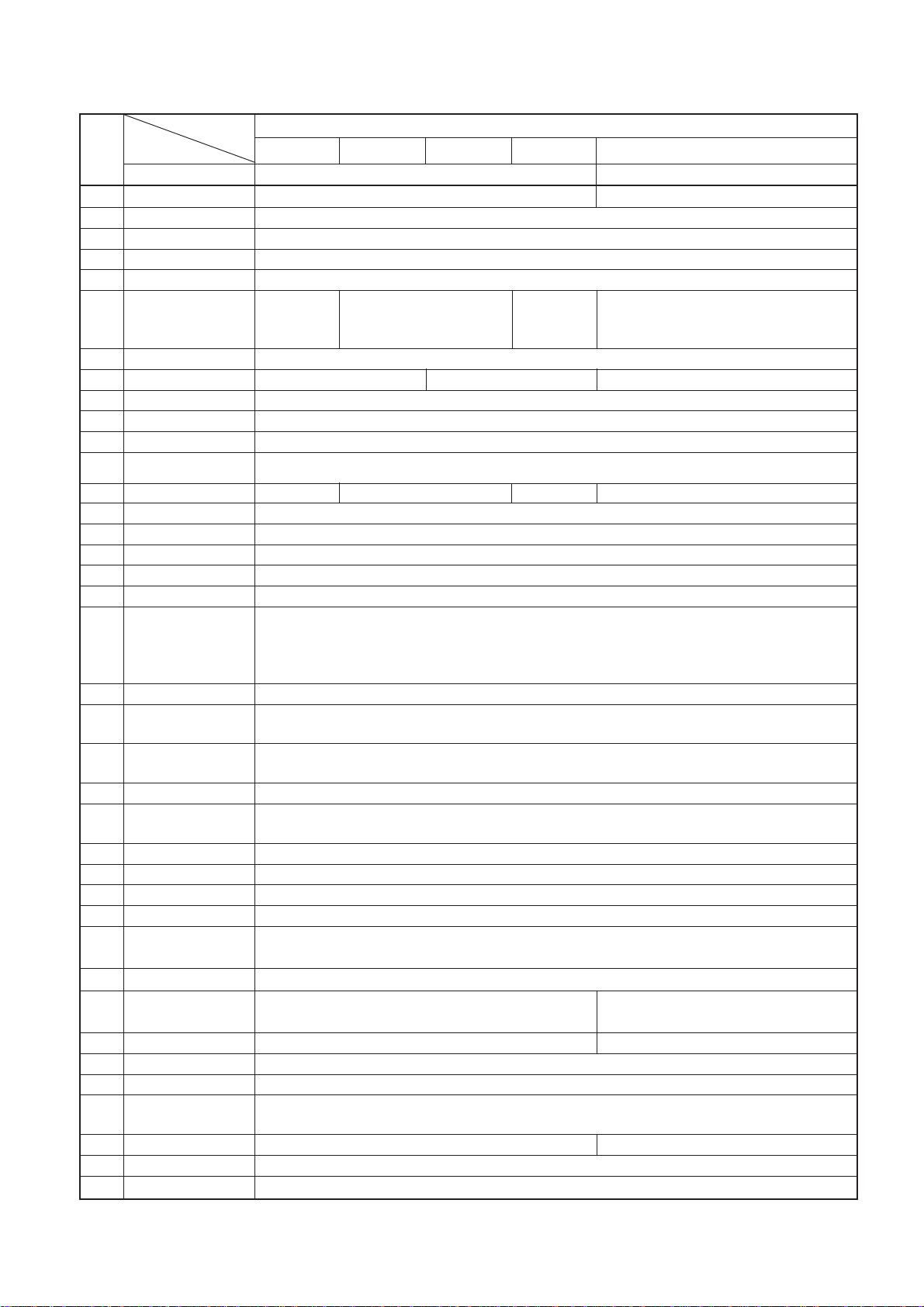
JUKI AMS-221EN Series Quick start guide

40087241
No.E389-00
ENGINEER’S MANUAL
Computer-controlled, Cycle Machine
With Input Function
AMS-221EN Series
®

PREFACE
This Engineer’s Manual is written for the technical personnel who are responsible for the service and maintenance
of the machine.
The Instruction Manual for these machines intended for the maintenance personnel and operators at an apparel
factory contains operating instruction in derail. And this manual describes “Standard Adjustment”, “Adjustment
Procedures”, “Results of Improper Adjustment”, and other important information which are not covered in the
Instruction Manual.
It is advisable to use the Input Instruction Manual, relevant Instruction Manual and Parts List together with this
Engineer’s Manual when carrying out the maintenance of these machines.
In addition, for the motor for the sewing machine with thread trimmer, refer to the separate Instruction Manual or
This manual gives the “StandardAdjustment” on the former page under which the most basic adjustment value is
described, and on the latter page “Results if Improper Adjustment” under which stitching errors and troubles
arising from mechanical failures and “Hoe to adjust” are described.

CONTENTS
1. Specifications ........................................................................................................ 1
2. Configuration........................................................................................................... 2
(1) Names of main unit .................................................................................................................. 2
(2) IP-420 operation panel............................................................................................................. 3
3. Standard adjustment ..............................................................................................4
(1) Adjustment of the throat plate auxiliary cover height......................................................... 4
(2) Adjustment of the feed bar auxiliary cover rail X ................................................................ 6
(3) Adjustment of the X movement top cover............................................................................ 6
(4) Main shaft connection/disconnection .................................................................................. 8
(5) Removal of main shaft motor and coupling....................................................................... 10
(6) Crank rod connection/disconnection ................................................................................. 12
(7) Crank balancer positioning ................................................................................................. 14
(8) Adjustment of intermediate presser cam ........................................................................... 16
(9) Adjustment of intermediate presser bar............................................................................. 16
(10)Intermediate presser variable connection /disconnection ............................................... 18
(11) Intermediate presser variable adjustments........................................................................ 20
(12)Intermediate presser drive arm ........................................................................................... 22
(13)Lower shaft backlash adjustment and connection/disconnection .................................. 24
(14)Oscillator gear positioning .................................................................................................. 24
(15)Adjustment of hook oil amount........................................................................................... 26
(16)Shuttle connection / disconnection and oil wick piping................................................... 26
(17)Adjusting the height of the needle bar ............................................................................... 28
(18)Hook adjustment................................................................................................................... 30
(19) Thread trimmer presser lifter cam connection/disconnection ........................................ 32
(20) Thread trimmer and presser origin sensor adjustment ................................................... 32
(21) Adjustment of the moving knife and counter knife position............................................ 34
(22) Floating amount of the thread tension disk ...................................................................... 34
(23) Second thread tension connection / disconnection......................................................... 36
(24) AT unit connection / disconnection.................................................................................... 38
(25) Wiper adjustment ................................................................................................................. 40
(26)Backlash adjustment for the X motor ................................................................................. 42
(27)Backlash adjustment for the Y motor ................................................................................. 42
(28)Adjustment of the tension of the X timing belt ................................................................. 44
(29)Adjustment of the tension of the Y timing belt ................................................................. 46
(30)How to remove rattles from the Y drive shaft .................................................................... 48
(31)Phase adjustment for the Y timing belt .............................................................................. 48
(32)Adjustment of the X-Y mechanism ..................................................................................... 50
(33)Pressure adjustment for the side plate bearing ................................................................ 52
(34)Initial length of the presser cylinder ................................................................................... 54
(35)Initial length of the 2-step stroke cylinder.......................................................................... 54
(36)Adjustment of the speed controller .................................................................................... 56
(37)Adjustment of the pressure reducer................................................................................... 58
(38) Making the origin setting gauge ......................................................................................... 60
(39) Adjusting the X origin sensor ............................................................................................. 60
(40) Adjusting the Y origin sensor ............................................................................................. 62
(41) Adjustment of the bobbin winder driving wheel position ................................................ 64
(42) Adjusting the bobbin winder amount ................................................................................. 64
(43) Adjustment of the shuttle upper spring and lower thread holder position .................... 66
(44) Shuttle felt............................................................................................................................. 66
(45) Shape of the shuttle race ring.............................................................................................68
(46) Adjustment of thread take-up spring ................................................................................. 68
(47) Needle thread clamp device connection/disconnection .................................................. 70
(48) Adjusting the needle thread clamp notch.......................................................................... 72

(49) Adjusting the needle thread clamp sensor........................................................................ 74
(50)Adjustment of tilt machanism of the machine head.......................................................... 76
4. Memory switch ...................................................................................................... 82
(1) Start and change .................................................................................................................... 82
(2) Function list............................................................................................................................83
5. Supplemental remarks of each function number and
explanation of each function ............................................................................. 100
(1) Feeding frame operational sequence setup ...................................................................... 100
(2) Fixed refuge position setup ................................................................................................ 104
(3) Bank function setup............................................................................................................. 105
(4) Port I/O setup........................................................................................................................ 108
(5) Simplified program setup....................................................................................................121
(6) Version display..................................................................................................................... 134
(7) Keylock setup....................................................................................................................... 135
(8) Customize function setting of key lock ............................................................................. 137
(9) Communication screens of the maintenance personnel level (Program rewrite) ......... 144
(10) Information screen at the maintenance personnel level ................................................ 148
(11) Test sewing function ......................................................................................................... 150
6. Test mode ........................................................................................................... 153
7. Printed wiring board and dip switch................................................................ 169
(1) Various printed wiring boards ............................................................................................ 169
(2) Dipswitch setup.................................................................................................................... 177
8. Table of exchanging gauge parts according to sewing specifications and
needle size used ................................................................................................ 178
9. Option list........................................................................................................... 179
(1) Method of pedal switch cable set connections................................................................. 186
10.Maintenance ....................................................................................................... 188
(1) Replacing the fuse ............................................................................................................... 188
(2) Changing the voltage specification.................................................................................... 189
(3) Greasing• lock-tight parts ................................................................................................... 190
(4) Parts to which grease • Locktight is applied ..................................................................... 191
(5) Replenishing the designated places with grease ............................................................. 200
11. Error code list .................................................................................................... 205
12. Message list....................................................................................................... 213
13.Troubles and corrective measures .................................................................. 217
(1) Mechanical parts .................................................................................................................. 217
(2) Sewing conditions ............................................................................................................... 221
(3) Electrical components......................................................................................................... 230
14.Circuit diagrams ................................................................................................ 239
(1) Block diagram ..................................................................................................................... 239
(2) Power supply circuit diagram A ........................................................................................ 240
(3) Power supply circuit diagram B ........................................................................................ 241
(4) Power supply circuit diagram C ........................................................................................ 242
(5) Servo motor circuit diagram.............................................................................................. 243
(6) Sensor-pedal circuit diagram ............................................................................................ 244
(7) MAIN•PANEL board circuit diagram ................................................................................. 245
(8) Motor•solenoid circuit diagram......................................................................................... 246
(9) Air system circuit diagram................................................................................................. 247
15.Drawing of the table........................................................................................... 248

– 1 –
1. Specifications
(Caution) Grease type, refer to (3) Application of grease and Locktight
No. Application
AMS-221ENSS AMS-221ENHS AMS-221ENHL AMS-221ENSL
AMS-221ENHS
Sub-class 2516 3020
1Sewing area
X-Direction (right, left) 250mm; Y-Direction (forward, backward) 160mm
X-Direction (right, left) 300mm; Y-Direction (forward, backward) 200mm
2 Max. sewing speed 2800sti/min (when sewing pitch is 3mm or less)
3 Stitch length 0.1 to 12.7mm (Min. resolution : 0.05mm)
4
Feed motion of feeding frame
intermittent feed (2-shaft drive by stepping motor)
5Needle bar stroke 41.2mm
S type: H type: S type: H type:
6Needle 134 No. 90 135 x 17 No. 110 134 No. 90 135 x 17 No. 110
(DP x 5#14) (DP x 17 #18) (DP x 5 #14) (DP x 17 #18)
7
Method to lift feeding frame
Air
8
Feeding frame shape
Right and left united Right and left separated Right and left united
9Lift of feeding frame Standard 25mm, Max. 30mm
10
Intermediate presser stroke
Standard 4mm (0 to 10mm)
11
Lift of intermediate presser
20mm
12 Standard 0 to 3.5mm (Max. 0 to 7.0mm)
13
Needle thread clamp device
S type H type S type H type
14
Needle thread tension
Active tension (electronic thread tension control mechanism)
15 Hook 2-fold semi-rotary hook
16 Lubrication Plane part: grease, hook part: minute volume lubrication (tank type)
17 Lubricating oil JUKI NEW Defrix oil No. 2 (equivalent to ISO VG32) (Lubrication system)
18 Grease 1.Penetration No. 2 lithium grease, 2. Templex N2, 3. Juki Grease A, 4. Juki Grease B (Caution)1.
Sewing machine, Media
19
Memory of pattern data
• Sewing machine :Max. 999 patterns (Max. 50,000 stitches/1pattern)/Max. 500,000 stitches
•Media :Max. 999 patterns (Max. 50,000 stitches/1pattern)/25million stitches
max.(CF card, 128M)/Approx. 50 milion stitches max. (CF card, 256M)
20
Temporary stop facility
Used to stop machine operation during a stitching cycle.
21 Enlarging/Reducing Allows a pattern to be enlarged or reduced on the X axis Y axis independently when sewing a pattern.
function 1% to 400% times (0.1% steps)
22 Enlarging/Reducing
Pattern enlargement / reduction can be done by increasing / decreasing either stitch length or the number of stitches.
method (When the pattern button is selected, the function available is only the adjustment of stitch length.)
23
Sewing speed limitations
200 to 2,800 sti/min (Scale : 100 sti/min steps)
Pattern No. selection method
(Sewing machine : 1 to 999, Media : 1 to 999)
25
No. of sheets counter
Up/Down method (0 to 9,999)
26 Sewing counter Up/Down method (0 to 9,999)
27
Bobbin thread counter
Up/Down method (0 to 9,999)
28 Memory back-up In case of a power interruption, the pattern being used will automatically be stored in memory.
Using jog keys, a 2nd origin (needle position after asewing cycle) can be set in the desired position within the sewing area
.
(The set 2nd origin is also stored in memory.)
30
Sewing machine moto
AC servo motor
W: 1,200mm L: 1,000mm H: 1,200mm W: 1,200mm L: 1,070mm H: 1,200mm
(Excluding thread stand) (Excluding thread stand)
32
Weight (gross weight)
201kg 210kg
33 Power consumption 700VA
34
Working temperature/humidity
Temperature: 5°C to 35°C, Humidity: 35 to 85% (no condensation)
Japan, JUS, export : 3-phase 200V to 240V (1-phase 100V/120V), China, Europe, general : 1-
phase 200V to 240V, Rating ±10%, 50/60Hz
36 Air pressure used Standard: 0.5 to 0.55MPa, Max. 0.55MPa Standard: 0.35 to 0.4MPa, Max. 0.55MPa
37 Air consumption 1.8dm3/min (ANR)
38
Needle highest position stop facility
After the completion if sewing, the needle can be brought up to its highest position.
Model name
Item
35
Supply voltage/frequency
24
Pattern selector facility
29
2nd origin setting facility
31 External dimensions
Intermediate presser
DOWN position variable

– 2 –
2. Configuration
(1) Names of main unit
Machine head
Wiper switch
Temporary stop switch
Feeding frame
Intermediate presser
Thread stand
Operation panel (IP-420)
Power switch
Control box
Foot pedal
Air regulator

– 3 –
(2) IP-420 operation panel
(Front view) (Right side view)
Touch panel • LCD display section
READY key →Changeover of the data input screen and the sewing screen can be
performed.
INFORMATION key →Changeover of the data input screen and the information screen can
be performed.
COMMUNICATION key →Changeover of the data input screen and the communication screen
can be performed.
MODE key →Changeover of the data input screen and the mode changeover screen
which performs various detail settings can be performed.
Contrast control
Brightness control
CompactFlash (TM) eject button
CompactFlash (TM) slot
Cover detection switch
Connector for external switch
Connector for control-box connection

– 4 –
3. Standard adjustment
(1) Adjustment of the throat plate auxiliary cover height
Standard Adjustment
Within 0.3mm
1) 2516
2) 3020
0.8 to 1.0mm

– 5 –
1) 2516
1. Loosen 2 setscrews and 6 setscrews .
2. Vertically move the throat plate auxiliary cover and the throat plate
auxiliary cover support to make adjustments so that the throat
plate auxiliary cover is positioned higher than the throat plate
and that the vertical difference between two is kept within 0.3mm.
Since then, fix them by means of 2 setscrews and 6 setscrews .
2) 3020
1. Loosen setscrews (2 pcs.) and setscrews (12 pcs.).
2. Vertically move throat plate aux. cover and throat plate aux. cover
and make adjustments so that the clearance becomes 0.8 to 1mm
between the upper face of throat plate aux. cover and the lower
face of lower plate mounting plate under the conditions that the
throat plate aux. cover is positioned higher than throat plate
and its step difference is kept within 0.3mm. Since then, fix the
setscrews (2 pcs.) and the setscrews (12 pcs.).
*Confirm that the clearance maintains its length at 0.8 to 1mm
throughout the moving range in Direction X.
oThe feed plate is caught by the
stepped part of the throat plate
andthe throat plate auxiliary cover
, thus causing deformation of
shape.
o Bending is caused in the feed
plate.
oThe lower plate is caught by the
stepped section of throat plate
and throat plate aux. cover .
Such an awkward condition
results in shape deformation.
oAbend is caused in the lower
plate.
oAproblem of contact is caused
with lower plate mounting plate
and throat plate aux. cover .
Adjustment Procedures Results of Improper Adjustment

– 6 –
(3) Adjustment of the X movement top cover
Standard Adjustment
Auxiliary cover
rail stop plate
(2) Adjustment of the feed base auxiliary cover rail X
Standard Adjustment
X movement bottom cover asm.

– 7 –
1. Loosen 8 setscrews .
2. Lay the X movement top cover asm. beneath the embossed part
of the Y guide rail.
3. Let the Y guide rail holder be pinched by the feed base auxiliary
cover rail Y and the X movement top cover asm. in order to
remove rattling.
At that time, 8 setscrews should be tightened tentatively to move
the X movement base forward and backward while removing rattles
uniformly.
4. Regularly tighten 8 setscrews .
(Caution) Apply a proper amount of grease on the sliding parts of
the Y guide rail holder .
oIf there is any rattling, this can be
a cause of noise.
oIf the rattling condition is removed
extremely, this can be a cause of
abrasion developed in the X
movement top cover asm. .
Adjustment Procedures Results of Improper Adjustment
1. Loosen 16 setscrews .
2. Lightly push the feed base auxiliary cover rail X in the direction of
the arrow and adjust the X movement top cover asm. so that it can
move smoothly without causing rattles. Since then, tighten 16
setscrews .
oIf there is any rattling, this can be
a cause of noise.
Adjustment Procedures Results of Improper Adjustment

– 8 –
(4) Main shaft connection/disconnection
1. Loosen the setscrew securing the main shaft counterbalance , and remove the taper screw .
2. Loosen 2 setscrews (through the screwdriver hole A), 2 setscrews , and 2 setscrews .
On this occasion, loosen No. 2 setscrew first, and completely remove No. 1 setscrew from the flat part of the
main shaft .
3. Remove the main shaft motor .
Refer to “3.-(5) Removal of the main shaft motor and coupling”.
4. Loosen 2 setscrews .
On this occasion, be aware that the balancer may rotate due to loosened setscrews .
5. Loosen 2 setscrews .
6. Loosen 2 setscrews .
On this occasion, completely remove No. 1 setscrew of the setscrews from the flat part of the main shaft
.
7. Loosen 2 setscrews and 2 setscrews .
8. Pull out the main shaft in the direction of Arrow C.
Screwdriver hole A
No. 1 setscrew
No. 2 setscrew
No. 2 setscrew
No. 2 set
screw
No. 1 setscrew
No. 1 setscrew
D
F
E
C
Procedures of disassembling
Main shaft taper hole

– 9 –
1. Insert the main shaft into the balancer , crank rod , bobbin winding drive wheel , hand pulley gear
A , intermediate presser eccentric cam , and the main shaft counterbalance in this order, and mount
this assembly on the frame.
2. Tighten the taper screw into the taper hole of the main shaft , and tighten the setscrew to secure the
main shaft counterbalance .
3. Lightly press the main shaft counterbalance in the direction of Arrow D and the middle metal in the
direction of Arrow E, and tighten 2 setscrews .
(Tighten No. 1 setscrew so that it touches the flat part of the main shaft . Then, tighten No. 2 setscrew.
Same procedure hereafter)
4. Tighten 2 setscrews and 2 setscrews . (Make sure that No. 1 setscrew touches the flat part of the
main shaft .)
5. Mount the main shaft motor and coupling .
Refer to “3.-(5) Removal of main shaft motor and coupling”.
6. Secure the eccentric cam of the intermediate presser with 2 setscrews . Refer to “3.-(8)Adjustment of
intermediate presser cam”.
7. Press the hand pulley in the direction ofArrow F to engage the hand pulley gear A with the hand pulley
gear B , and secure them with 2 setscrews .
8. Secure the crank rod with 2 setscrews . Refer to “3.-(6) Crank rod connection/disconnection”.
9. Secure the balancer with 2 setscrews . Refer to “3.-(7) Crank balancer positioning”.
10. Secure the bobbin winding drive wheel with 2 setscrews . Refer to “3.-(42) Adjustment of the bobbin
winder driveing wheel position”.
* Make sure that no torque is applied by rotating the main shaft .
Procedures of assembling

– 10 –
(5) Removal of main shaft motor and coupling
1. For removal of the main shaft motor with the coupling,
Loosen 2 setscrews on the main shaft side of the coupling , and remove 4 setscrews securing the
motor.
2. For removal of the coupling from the main shaft motor , loosen 2 setscrews on the main shaft motor
side.
(Caution) The screw (hole) that can be seen first is No. 1 setscrew when the main shaft is turned
in the forward direction AA
AA
A. For loosening, loosen No. 2 setscrew first, and for tightening,
tighten No. 1 setscrew first.
No. 1 setscrew
No. 1 setscrew
0.7mm
A
No. 2 setscrew
Procedures of disassembling

– 11 –
1. For mounting the main shaft motor with the coupling,
(1) Tighten 4 setscrews that securing the motor, and tighten 2 setscrews on the main shaft side of the
coupling .
(2) The cords of the main shaft motor should be positioned in the lateral direction.
2. For connecting the coupling to the main shaft motor,
(1) Provide a clearance of 0.7 mm between the coupling and main shaft motor .
(2) Apply No. 1 setscrew of the coupling to the flat section of the main shaft motor , the main shaft
and secure it.
3. For engaging the coupling,
(1) Position the setscrew (No. 1 setscrew) on the main shaft motor side between 2 setscrews on the
main shaft side, and engage the coupling.
Procedures of assembling

– 12 –
(6) Crank rod connection/disconnection
1. Loosen 3 setscrews and 2 setscrews . On this occasion, loosen No. 2 setscrews first, and completely
disengage No. 1 setscrews from the flat section of the oscillator shaft .
2. Pull out the oscillator shaft in the direction of Arrow A.
3. Remove the main shaft according to “3.-(4) Main shaft connection/disconnection”, and remove the crank
rod unit .
22.1 to 22.6mm
Face B No. 2 setscrew
No. 1 setscrew
C
A
E
D
Procedures of disassembling
No. 1 setscrew
No. 2 set
screw

– 13 –
1. Mount the main shaft according to “3.-(4) Main shaft connection/disconnection”, and mount the crank rod
unit .
2. Adjust the clearance to 22.1 to 22.6 mm between the under cam of the crank rod unit and Face B
(middle metal bearing mounting face) of the frame, and secure the cam with the setscrew .
(Apply No. 1 setscrew to the flat section of the main shaft and tighten it first, then tighten No. 2 setscrew.
Same procedure hereafter)
3. Pass the oscillator through the oscillator shaft , and mount them on the frame.
4. Pass the thrust collar through the oscillator shaft . Lightly press the oscillator shaft in the direction of
arrow C and the thrust collar in the direction of Arrow D, and tighten 2 setscrews . Make sure that No.
1 setscrew touches the flat section of the oscillator shaft .)
5. Secure the oscillator according to “3.-(14) Oscillator gear positioning”.
(Caution) 1. Make sure that no torque is applied by rotating the main shaft .
2. When the crank rod unit is connected, disconnected, or positioned, or the oscillator
is positioned, be sure to grease two specified positions and the gear section (E) of the
oscillator .
3. After positioning the crank rod unit (under cam ), be sure to perform “3.-(14) Oscilla-
tor gear positioning”. Wrong positioning of the under cam or oscillator may cause
frictional wear or lock-up.
Procedures of assembling

– 14 –
(7) Crank balancer positioning
[Rotating direction]
When the needle bar lowers and the clearance between the needle bar connecting and needle bar lower
bushing is 4.6 mm, 2 setscrews of the crank balancer becomes horizontal position.
[Axial direction]
Bring the main shaft eccentric cam into contact with the crank balancer .
Standard Adjustment
B
A
4.6mm

– 15 –
If the main shaft eccentric cam is not secured, the main shaft eccentric
cam should be positioned first.
1. Remove 4 setscrews , then remove the crank rod cover .
2. Loosen 2 setscrews securing the crank balancer .
3. Turn the main shaft in the forward direction Aso that the needle bar
lowers and the clearance between the needle bar connecting
and needle bar lower bushing is 4.6 mm.
4. Secure the crank balancer with 2 setscrews under the condi-
tions that 2 setscrews securing the balancer are horizontally
positioned and the balancer is moved in the direction of Arrow B
to make it into contact with the main shaft eccentric cam . For
tightening 2 setscrews , tighten them alternately.
Adjustment Procedures Results of Improper Adjustment
oIf the mounting angle of the crank
balancer is wrong, vibration
during sewing will be intensified.
oIf the sewing machine is used for
a long time under the condition of
wrong securing position, the life
of main shaft bearing may be
shortened.

– 16 –
(8) Adjustment of intermediate presser cam
(9) Adjustment of intermediate presser bar
13.5mm
Standard Adjustment
Standard Adjustment
Align
Align
This manual suits for next models
4
Table of contents
Other JUKI Sewing Machine manuals

JUKI
JUKI HZL-UX8 User manual

JUKI
JUKI AB-1351 User manual

JUKI
JUKI ACF-172-1790 User manual

JUKI
JUKI MO-6704D User manual

JUKI
JUKI HZL-F series User manual

JUKI
JUKI PLK-J10050R User manual

JUKI
JUKI DX-4000QVP User manual

JUKI
JUKI PS-800SB-2850 Series User manual

JUKI
JUKI DDL-8700-7 User manual

JUKI
JUKI DDL-8700-7 Quick start guide