Possibletroubles and phenomena caused by
Improper
adjustments
(1)
When
sewing
materials whichtend to flutter while
being
stitched, set the
needle
bar
slightly
lower
than the standard height.
When
sewing
a
heavy-weight
material,
providing
it isnot of a type that tends to flutter, set the
needle bar slightly higher
than
the
standard
height.
(2) When using a synthetic or soft and thin thread
(for example, cotton thread #80), in order to
prevent it from falling down and snagging, do not
allow it to form a large loop.
(3) If
the
shuttle comes closer to
the
needle than
0.05
mm,
they
may touch and scratch each other.
The scratcheson their surfaceswill
damage
a thin
or
synthetic
thread.
If
the
clearance is greater
than
0.1 mm stitch-
skipping
will result.
(4) If
the
shuttle
driver
dosen't
come
into
close
contact
with
the
needle,
the
needle will
bend
backwards.
The
bent
needle
will
hit
the
blade
point
of
the
shuttle
scratching
them
both.
If
this
happens
the
thread
is likely
to
be
broken
or
torn
by
these
scratched
surfaces.
If the needle isonly slightlybent, stitching will not be
affected. If, however, it isbent too much, it may
cause
stitch-skipping.
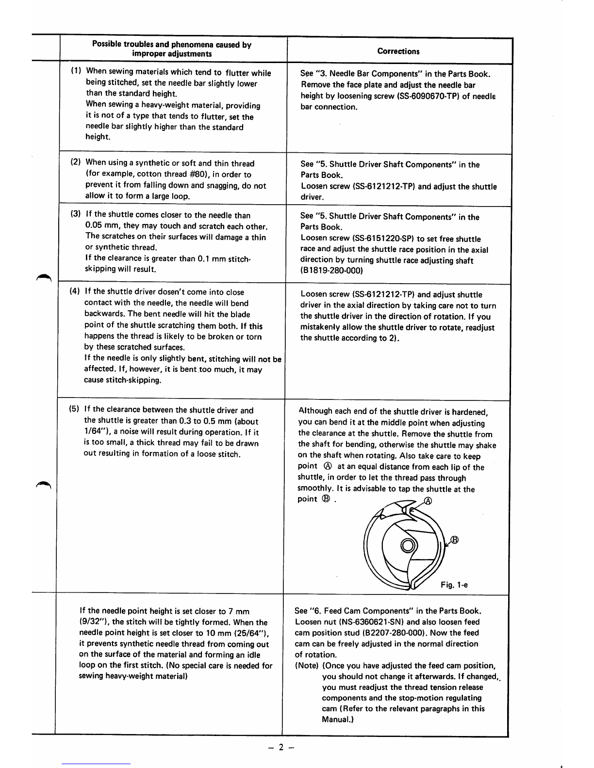
(5) If
the
clearance between
the
shuttle
driver and
the shuttle isgreater than 0.3 to 0.5 mm (about
1/64"), a noisewill result during operation. If it
is
too
small, a thick thread may fail to be drawn
out
resulting
in
formation
of
a
loose
stitch.
If
the
needle
point
height is set closer to 7 mm
(9/32"), the stitch will be tightly formed. Whenthe
needle point height is set closer to 10 mm
(25/64"),
it prevents synthetic needle thread from coming
out
on
the
surface of
the
material and forming an idle
loop on
the
first stitch. (No special care is needed for
sewing heavy-weight material)
Corrections
See
"3.
Needle Bar
Components"
in
the
Parts Book.
Remove
the
face plate and adjust
the
needle bar
height
by
loosening
screw
(SS-6090670-TP)
of
needle
bar
connection.
See
"5.
Shuttle
Driver
Shaft
Components" in
the
Parts
Book.
Loosen screw (SS-6121212-TP) and adjust
the
shuttle
driver.
See "5. Shuttle
Driver
Shaft Components" in the
Parts
Book.
Loosen screw (SS-6151220-SP)
to
set free
shuttle
race and adjust
the
shuttle race position in
the
axial
direction by turning shuttle raceadjustingshaft
(B1819-280-000)
Loosen screw (SS-6121212-TP) and adjust shuttle
driver in
the
axial direction by taking care not to
turn
the shuttle driver in
the
direction of rotation. If you
mistakenly allow the shuttle driver to rotate, readjust
the
shuttle
according
to
2).
Although
eachend of the shuttledriverishardened,
you can bend it at the middle point when adjusting
the
clearance
at
the
shuttle.
Remove
the
shuttle
from
the shaft for
bending,
otherwise the shuttle mayshake
on the shaft when rotating. Alsotake care to keep
point
(3)
at an
equal
distancefrom each lipof the
shuttle, in order to let the thread passthrough
smoothly. It is advisable
to
tap
the
shuttle
at
the
point © .
Fig. 1-e
See
"6.
Feed
Cam
Components"
in
the
Parts
Book.
Loosen
nut
(NS-6360621-SN)
and
also
loosen
feed
cam
position
stud
(B2207-280-000).
Now
the
feed
cam
can
be
freely
adjusted
in
the
normal
direction
of
rotation.
(Note)
(Once
you
have
adjusted
the
feed
cam
position,
you
should
not
change
it
afterwards.
If
changed,
you
must
readjust
the
thread
tension
release
components
and
the
stop-motion
regulating
cam
(Refer
to
the
relevant
paragraphs
in
this
Manual.)
- 2 -