JUKI HZL-NX7 User manual

SERVICE MANUAL
HZL-NX7
COMPUTER SEWING MACHINE

Be sure to observe the following to protect against a re, electrical shock, injury or damaged components.
* Be sure to unplug the machine before disassembly, assembly or adjustment of the machine.
* Be sure to carefully prevent electric cords from being caught, coated surfaces from being damaged
as well as wrong wiring during assembly.
* Be sure to use the proper genuine parts when changing any of the machine parts.
CAUTION:
CONTENTS
[1] Specications of HZL-NX7 ...................................................................................1
[2] Search by trouble (related to mechanical components) ...................................3
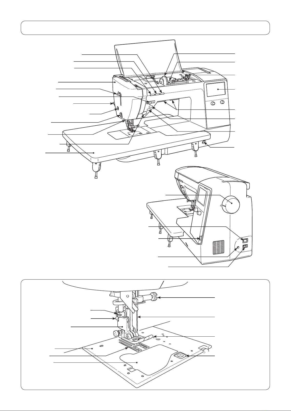
[3] Principal parts .......................................................................................................4
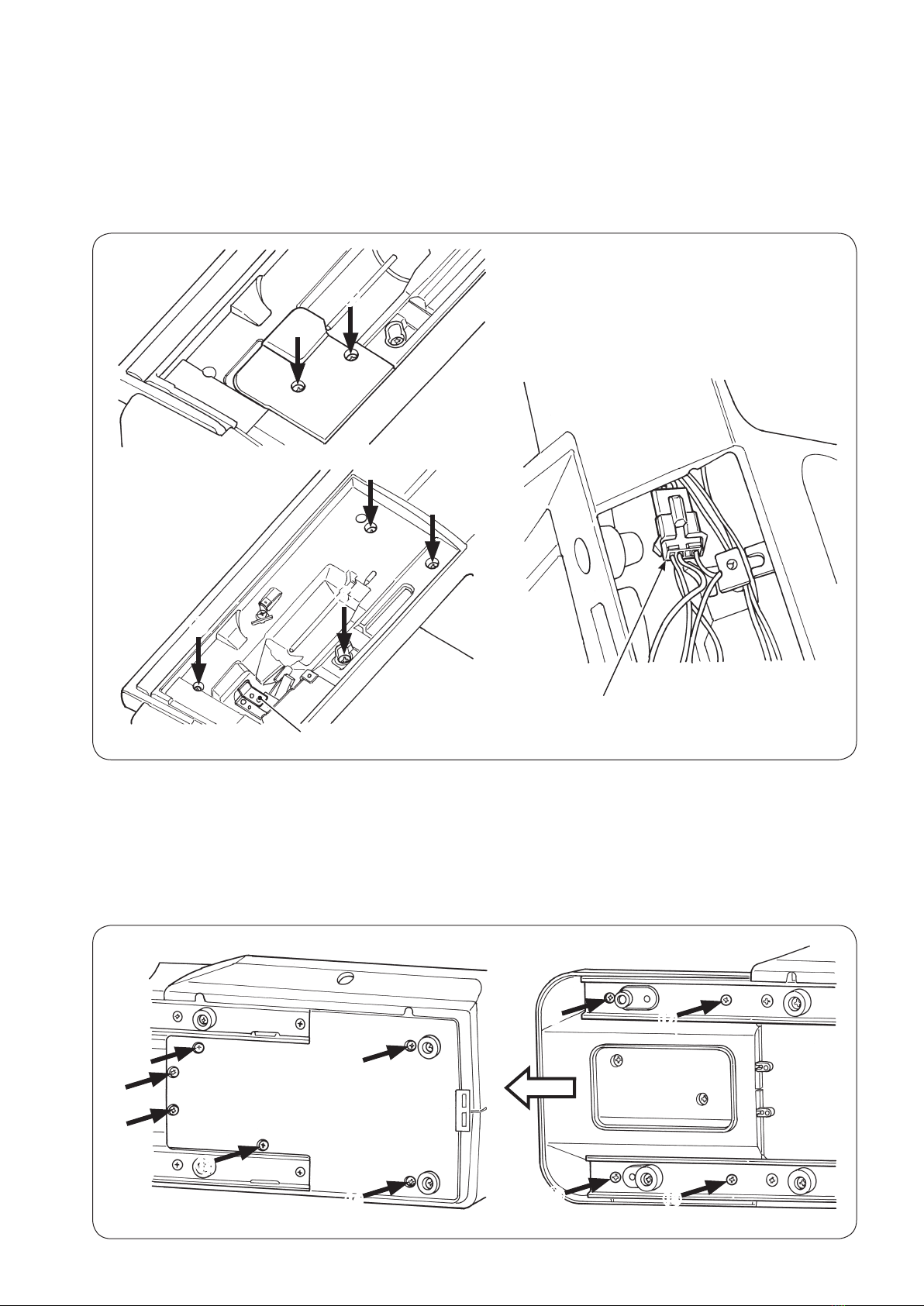
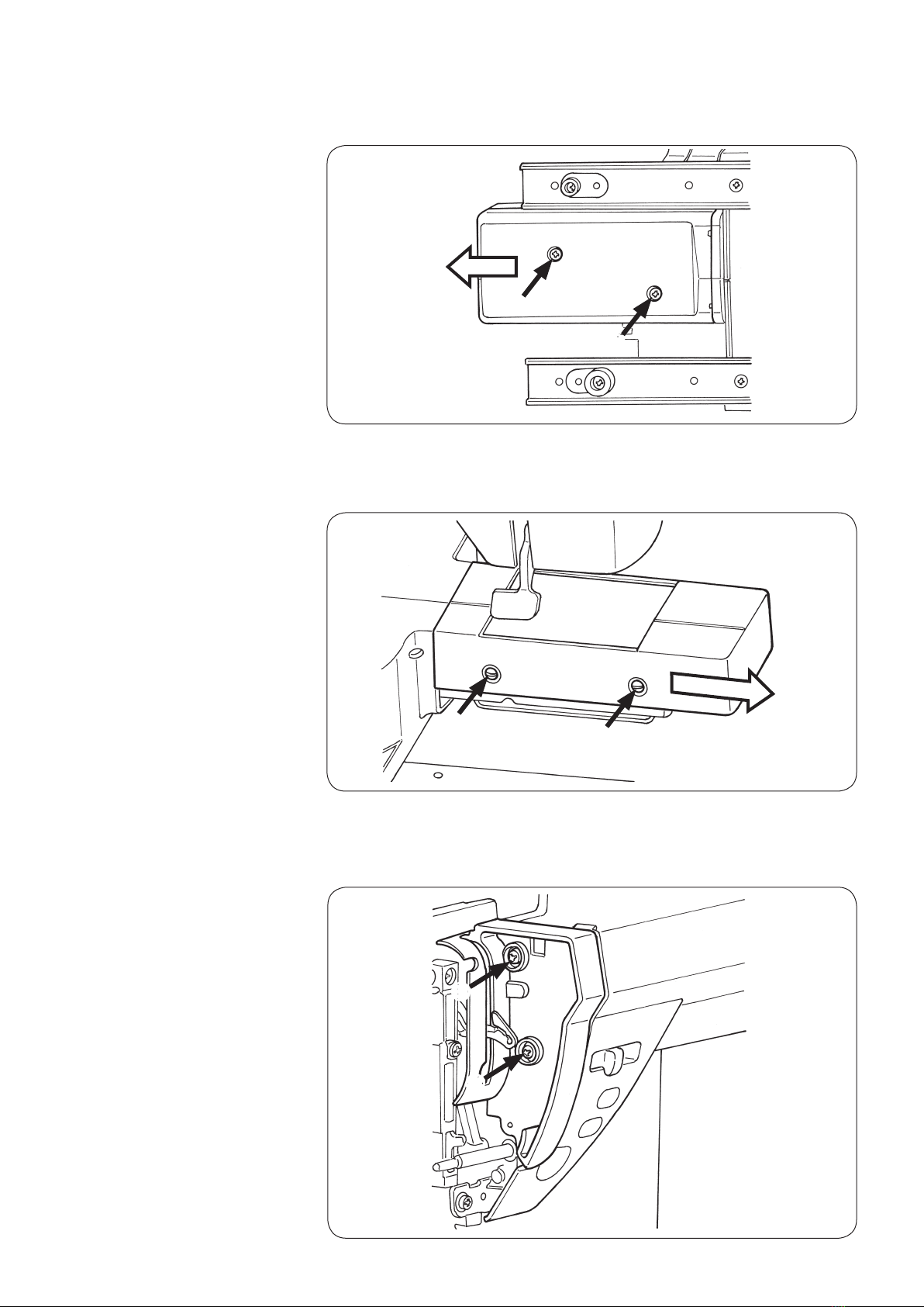
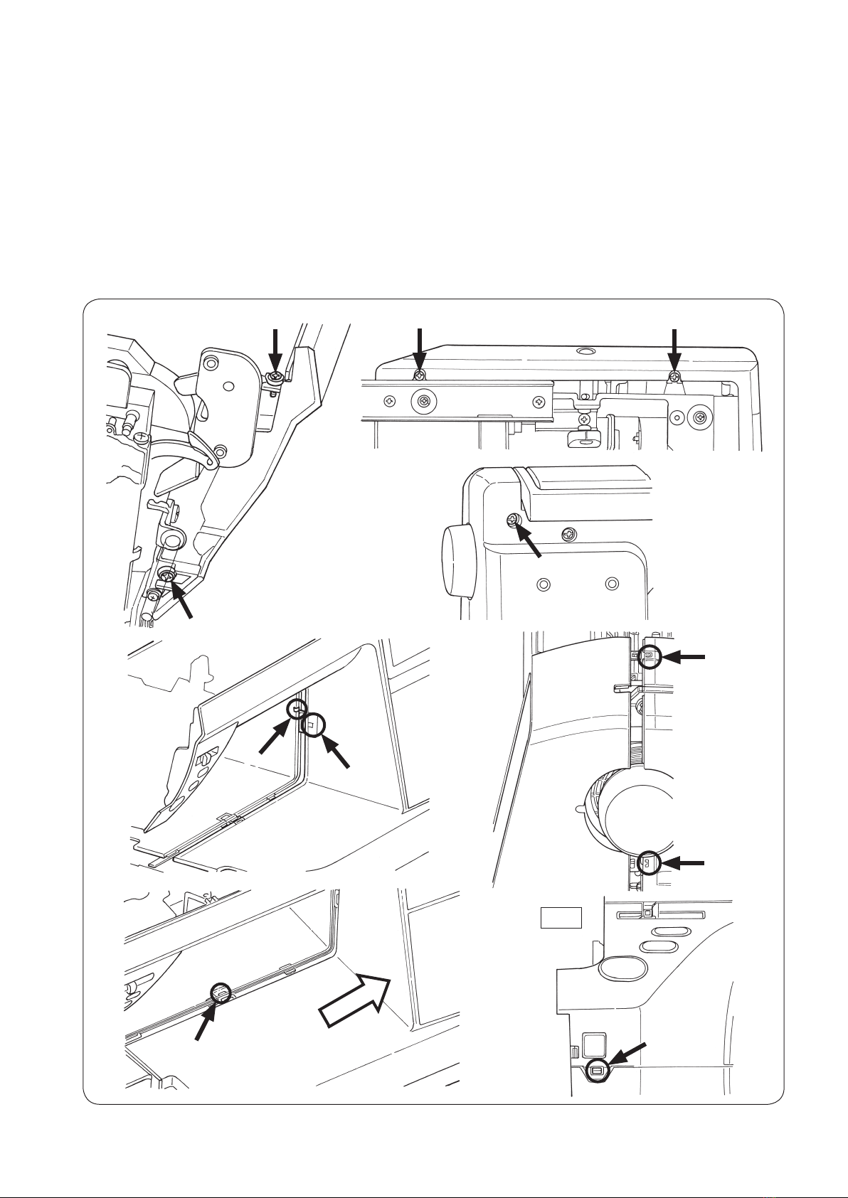
[4] Disassembling the machine covers ....................................................................5
[5] PCB connection diagram ...................................................................................10
[6] Adjustment ..........................................................................................................14
6-1 Adjusting the needle bar height ................................................................14
6-2 Adjusting the needle entry point ...............................................................15
6-3 Feed dog height ..........................................................................................16
6-4 Timing belt ...................................................................................................17
6-5 Feed timing ..................................................................................................17
6-6 Adjusting the shield ....................................................................................18
6-7 Hook driving shaft coupling and the lateral timing of the hook driving
shaft .............................................................................................................19
6-8 Timing between the needle and the hook .................................................20
6-9 Clearance between the needle and the blade point of hook ...................21
6-10 Position of the hook rotation stopper plate ...........................................22
6-11 Adjusting the bobbin thread tension .......................................................22
6-12 Adjusting the needle thread tension .......................................................23
6-13 Vertical position of the needle threading hook ......................................24
6-14 Adjusting the auxiliary hook height ........................................................25
6-15 Adjusting the opening amount of auxiliary hook ...................................26
6-16 Adjusting the presser bar height .............................................................26
6-17 Motor belt ...................................................................................................27
6-18 Longitudinal feed ......................................................................................28
6-19 Presser foot lifting ....................................................................................29
6-19-1 Position of the presser foot lifting motor .......................................29
6-19-2 Adjusting the height of the auto-lifter .............................................30
6-20 Thread trimming ........................................................................................31
6-20-1 Attaching/removing the thread trimmer unit ..................................31
6-20-2 Adjusting the thread trimming switch .............................................32
6-21 Attaching/removing the top feed dog .....................................................33
6-22 Position of the automatic DF motor ........................................................34
6-23 Service mode .............................................................................................35
6-23-1 Service mode screen ........................................................................35
6-23-2 Service-mode items and descriptions ............................................35

– 1 –
(1) Power switch
• 220-240V AC common to 50/60 Hz
• 120V AC common to 60 Hz
(2) Power consumption
• 85 W
(3) Dimensions and weight
• Dimensions Main unit: 575 (width) × 240 (depth) × 310 (height) (mm)
• Weight Main unit: 14.8 kg
(4) Revolution control
• Slide style speed control
Straight stitch 80 to 1,050 sti/min (SPM)
Pattern stitch 80 to 750 sti/min (SPM)
Reverse stitch 80 to 1,050 sti/min (SPM)
(Sewingspeedotherthanthespeciedrangecanbesetoptionally.)
80 to 1,050 sti/min (SPM) (when the speed controller is used.)
Bobbinwinding 1,500to3,000sti/min(SPM)
Low-speed start 80 to 110 sti/min (SPM) (approx. 1 second only when the power switch is turned ON.)
• Foot controller
Evenwhenthefootcontrollerisused,thespeedcontrolfunctionbymeansoftheslideriseffective.
Tostopthemachine,eitherreleasethefootcontrollerorpressstart/stopbutton.
Thenumberofrevolutionsiscontrolledinthewaysamewiththecaseoftheslidespeedcontrol.
Toe-uppedalingfunctioncanbesetoptionally.
• Safety control
When the motor shaft of the sewing machine is accidentally constrained, the power supply to the motor is
stopped within two seconds.
Whenthemotorisoverheated,thebuiltinthermalswitchstopsthepowertothemotor.
Notethatthemachinecanberestartedoncethemotorspontaneouslycoolsdown.
(5) Stop position
•Uponnishingsewing,themachinestopsaccordingtothepresetneedlestopposition(withitsneedleupor
down).
•Uponnishingreversestitching,themachinestopswithitsneedledown.
• Needle moves down when the machine has preset so that the needle stops at its up position and needle up/
downbuttonispressed.
• Needle moves up when the machine has preset so that the needle stops at its down position and needle up/
downbuttonispressed.
• In the case of fault, the machine stops immediately (stop position varies).
(6) Zigzag width
• Max. 7 mm depending on the pattern selected
(7) Amount of feed
•Theamountoffeedischangedinincrementsof0.2mmbythestitchlengthadjustingdial(orbutton).
(Fortheparallelpartsofabuttonholeandsatinstitches,theamountfeedischangedinincrementsof0.1mm.)
Default setting: 2.4 mm (for straight stitching)
[1] Specications of HZL-NX7

– 2 –
(8) Pattern selection
• Selection is made on the touch panel
(9) Number of patterns that can be selected
• Max. 70 patterns
(10) Number of patterns
• 351
(11) Automatic threading device
•Thehooksectionmakesaturnbyloweringthethreadinglever,andautomaticallyreturnstoitsoriginalposition
after completion of threading.
(12) Automatic lock stitch
WhenthebacktackingswitchisturnedON:
• Straight stitch: Three stitches are sewn in normal direction and three stitches are sewn in reverse direction at
thebeginningandend(thereverseswitchisturnedON)ofsewing.
Amount of feed: Same with the preset amount of feed
• Other patterns: Zero-feed is inserted and one each stitch is sewn in the normal and reverse directions at the
beginningandend(thereverseswitchisturnedON)ofsewing.
Amount of feed: Fixed at 0.4 mm
(13) Buttonholing
Auto-returntypefullautomaticbuttonholing
Buttonholing size detection
(14) Save and call patterns
Selectedpatternsandpatternsettingscanbestoredinmemory.
Inaddition,thepatterncanbecalledupfrommemoryforsewing.
Numberofpatternsthatcanbestoredinmemory:10(folders)
(15) Helpful messages
• Presser foot lifting lever
• Buttonholing foot
• Display of pattern storage limitation
• Pattern clear prompt
• Memory storage
• Acceptance of setting change
• 2-needle setting
• Motor lock
• Straight stitch selection
• Throat plate has come off
• Top feed

– 3 –
[2] Search by trouble (related to mechanical components)
Phenomenon Itemtobechecked
Faulty thread tension 6-10: Position of the hook rotation stopper plate
6-11:Adjustingthebobbinthreadtension
6-12:Adjustingtheneedlethreadtension
Stitch skipping 6-1:Adjustingtheneedlebarheight
6-2:Adjustingtheneedleentrypoint
6-5: Feed timing
6-8:Timingbetweentheneedleandthehook
6-9:Clearancebetweentheneedleandthebladepointofhook
Threadbreakage 6-1:Adjustingtheneedlebarheight
6-8:Timingbetweentheneedleandthehook
6-10: Position of the hook rotation stopper plate
Hitch stitch 6-2:Adjustingtheneedleentrypoint
Faulty material feed 6-3: Feed dog height
6-16:Adjustingthepresserbarheight
6-22: Position of the automatic DF motor
Contactbetweenneedleandthroatplate
or hook
6-2:Adjustingtheneedleentrypoint
6-5: Feed timing
6-8:Timingbetweentheneedleandthehook
Faulty pattern shape 6-3: Feed dog height
6-18: Longitudinal feed
Faulty automatic thread trimming 6-6:Adjustingtheshield
6-20-1: Attaching/removing the thread trimmer unit
6-20-2:Adjustingthethreadtrimmingswitch
Faulty operating noise 6-4:Timingbelt
6-17:Motorbelt
Needle threader 6-13: Vertical position of the needle threading hook
Fails to start sewing 6-19-2:Adjustingtheheightoftheauto-lifter
Faulty automatic presser foot lifting height 6-19-2:Adjustingtheheightoftheauto-lifter

– 4 –
[3] Principal parts
Spool cap (large)
Spool pin
LCD Screen
Face plate cover
Threading lever
Start/stopbutton
Presser foot lifting lever
Needle setscrew
Needle
Presser foot
Sensorpinholeforbuttonholing
Presserfootreleasingbutton
Feed dog
Throat plate
Hook cover
Bobbinwinding
shaft
Hook cover release
button
Presser foot holder
Threadtrimmingbutton
Widetable
Thread cutter Lockstitchbut-
ton
Speed controller
Needleup/downbutton
Knee lifting lever
hole
Light under arm
Reverse stitch
button
Presserfootautoliftbutton
Hand wheel (pulley)
Power switch
Machine-socket-inlet
Foot-controller-jack
USB insertion slot
Cloth puller top
feed device
Presser foot holder setscrew

– 5 –
○Toremovethetopcover,bowthehingesectionoftherightsideofthecover.
○Remove setscrews 1and 2from the face cover.
Then, remove the face cover.
○Fittingaat-bladescrewdriver(T-shape)inthenearestslotinthethroatplate,
push up the throat plate with the screwdriver until it comes off.
Then remove the throat plate.
[4] Disassembling the machine covers
1) Top cover
2) Face cover
3) Throat plate
T-shape
❶❷

– 6 –
❺
❻
❼
❽
❸
❹
○Remove setscrews 4and 5from the thread tension cover.
Remove the thread tension cover.
○Remove setscrews 6to !0 from the spool cover.
○Removethebobbinwindingmotorjunctioncablefromthejunctionconnector.
○Remove the spool cover from the main unit of the machine, paying attention to
thebasetension.
4) Spool cover
Base tension
○Remove setscrews ❾to ofthebottomcoverB(onthehandwheelside)to
detachthebottomcoverB.
○Remove setscrews to ofthebottomcoverA(ontheframeside).Draw
outthebottomcoverAinthedirectionofthearrowwhilepushingupthetipof
the cover.
5) Bottom cover
Junction connector
❾

– 7 –
○Removefree-armlowerbottomcoversetscrewsand .Pulloutthebot-
tom cover of the free arm in the direction of the arrow.
6) Bottom cover of the
free arm
○Remove free-arm upper cover setscrews and . Pull out the upper cover
of the free arm in the direction of the arrow.
7) Upper cover of the
free arm
○Remove setscrews and from the face plate cover.
Remove the face plate cover.
8) Face plate cover

– 8 –
AB
F
D
C
EG
9) Front panel ○Remove setscrews to from the front panel.
○Put a thin screwdriver in the notch Ain the rising section under the arm and
pry off the front panel and hook Bof the rear panel. (Fig 1)
○Detach clinch nails (Cand D) of the front panel and rear panel, while pushing
down the front panel.
○Opening the right side of the front panel in the direction of the arrow, tap E
section with your hand to remove hook Flocatedatthebedsurface.
○Lastly, remove hook Glocatedatthelowersideofthemachinejaw.
○If needed, remove the switch/slide VR connector (CN17) and panel I/F con-
nector (CN19) from the main PCB. Then, remove the LED1 connector (CN208).
Fig.1

– 9 –
10) Rear panel ○Remove setscrews to from the rear panel.
Remove the rear panel with the presser foot lifting lever raised.
Main PCB
Panel I/F
(CN19)
SW/slide
volume PCB
(CN17)
LED1
(CN208)
Panel PCB

– 10 –
[5] PCB connection diagram
• Main PCB Connec-
tor No. Destination Termi-
nal No.
CN13 Presser-lifter
STM
1A
4.0Ω
2 A
3 B
4.0Ω
4B
CN14 Top feed STM 1 A
4.0Ω
2 A
3 B
4.0Ω
4B
CN15 Thread tension
STM
1A
4.0Ω
2 A
3 B
4.0Ω
4B
5 GND
6 Origin detection signal
7 5V
CN16 BH sensor 1 GND
2 BHR SW
3 BHS SW
4 3.3V
CN17 SW/slide vol-
ume PCB
1 LED G
2 LED R
3 Reverse stitch switch
4 S/S switch
5Thread trimming switch
6Needle up/down switch
7 Auto-lifter switch
8 Lock stitch switch
9 GND
10 Speedcontrolvariable
resistor
11 GND
12 3.3V
CN18 Reserve
(Unused)
2 GND
4 GND
CN19 PanelI/Fcable
asm.
1 5V
2 5V
3 GND
4 GND
5 RXD
6 TXD
7 S.STATE
8 UDET
9 Reset
10 5V
11 5V
12 Panel detection signal
13 GND
14 GND
15 NC
CN17
CN6
CN31
CN3
CN15
CN13
CN20
CN5
CN14
CN4
CN29
CN25
CN30
CN9
CN19
CN27
CN28
CN26 CN16 CN2 CN18 CN34 CN1
Connec-
tor No. Destination Termi-
nal No.
CN1 Debug
(Unused)
1 3.3V
6 GND
CN2 Flash memory
interface
1 5V
5 GND
CN3 Needle throwing
STM
1A5.0Ω
2 A
3 B 5.0Ω
4B
CN4 Feed STM 1 A4.0Ω
2 A
3 B 4.0Ω
4B
CN5 Thread trimming
STM
1A4.0Ω
2 A
3 B 4.0Ω
4B
5 GND
6 Origin detection signal
CN6 Potentiometer
cableasm.
1 3.3V
2 Position detection
signal
3 GND
CN9 Throat plate
switch PCB
1 Throat plate switch 1
2 Throat plate switch 2
3 GND

– 11 –
• Power PCB
Connector No. Destination Check
CN1 Power SW AC input
CN2 Power supply relay lead wire 1-2PIN 29V, 4-5PIN GND (FG)
CN1
CN2
Connec-
tor No. Destination Termi-
nal No.
CN20 Automatic DF
STM
1A
4.0Ω
2 A
3 B
4.0Ω
4B
CN25 Main shaft de-
tection PCB
1 5V
2 Motor pulse
3 S1
4 S2
5 S3
6 GND
CN26 Bobbinwinding
motor
1Bobbinwinderswitch
2 GND
3Bobbinwindermotor(+)(29V)
4Bobbinwindermotor(-)
CN27 Controller socket 1 GND
2 Controller
CN28 Power supply
relay lead wire
1 29V
2 29V
3 NC
4 GND
5 GND
CN29 MotorlterPCB 1Mainmotor(+)(29V)
2 Main motor (-)
3 FG
Connec-
tor No. Destination Termi-
nal No.
CN30 Knee lifter slide
VR PCB
1 3.3V
2 Knee lifter position detec-
tion signal
3 GND
CN31 Presser foot lifting
switchcableasm.
1 Presser foot lifting switch
2 GND
CN34 Top feed detection
PCB
1 3.3V
2 Top feed detection signal
3 GND

– 12 –
• Panel PCB
Connec-
tor No. Destination Terminal
No.
CN200 PanelI/Fcable
(asm.)
1 5V
2 5V
3 GND
4 GND
5 TXD
6 RXD
7 S.STATE
8 UDET
9 Reset
10 5V
11 5V
12 Panel detection signal
13 GND
14 GND
15 NC
CN202 Touch panel 1 3.3V
2 - 5 Touch panel signal
6 GND
CN203 LCD 1 - 4 NC
5 GND
6 NC
7 - 36 LCD signal
37 3.3V
38 GND
39 Backlight(+)
40 Backlight (-)
CN204 USB 1 5V
2 - 3 USB signal
4 GND
Connec-
tor No. Destination Terminal No.
CN205 Reserve (Unused) 1 5V
5 GND
CN206 Write 10 GND
11 3.3V
12 - 14 GND
CN207 For external power
supply
1 5V
2 GND
CN208 On hand LED PCB 1 1 5V
CN209 On hand LED PCB 2 1 5V
CN210 Under arm LED PCB 1 5V
CN211 Under arm LED PCB 1 5V
CN212 Reserve (Unused) 5,8,22 - 24 3.3V
16,19 GND
CN207
CN203
CN202
CN211
CN210
CN209
CN208
CN206
CN212
CN205
CN200
CN204

– 13 –
• Connection block diagram
CN18
CN25
Bobbin
winding motor
4P
Unused
BH sensor
Main shaft
detection PCB
6P
Throat plate
switch PCB
CN31
CN6
2P
3P
Potentiometer cable asm.
Thread tension
origin detection PCB
CN3
4P
CN15
CN13
7P
4P
CN20
4P
Needle
throwing STM
Feed STM
CN29
3P
Main motor
CN9
CN19
3P
3P
15P
CN27
CN28
2P
5P
Power supply relay
lead wire
Power SW Power cord
Controller socket Foot controller
CN200
40P
CN205
Unused
LCD
480×272
Panel PCB
Touch panel
Main PCB
Motor filter
PCB
BLACK
WHITE
6P
6P
Top feed
STM
4P
4P
CN1
Top feed detection PCB
4P
Flash memory
interface
CN4
CN14
CN5
GREEN
CN17
SW/slide volume PCB
CN204
USB
Write
CN206
CN207
(For
external
power
supply)
GREEN
Thread trimmer
origin detection SW
CN30
Knee lifter slide
VR PCB
BLACK
12P
3P
15P
CN212
Unused
Presser foot lifting switch
cable asm.
Thread
tension STM
Presser-lifter
STM
Automatic
DF STM
Thread
trimming STM
BLUE
WHITE
RED
Power
PCB
CN2
CN1
Panel I/F cable asm.
Under arm
LED PCB 2
On hand LED
PCB 1
CN208
CN209
CN210
CN211
2P
2P
2P
2P
Unused
CN202 CN203
CN26 CN16 CN2 CN34
On hand LED
PCB 2
Under arm
LED PCB 1
RED

– 14 –
[6] Adjustment
6-1 Adjusting the needle bar height
○Remove the face cover.
Adjustmentvalue:
・
Distancefromthebottomendofthepininsideneedlebarsurfacetothetopsurfaceofthethroatplate:
19 mm
・
Whentheneedleismounted,theneedleeyetiltsrightwardby2degrees.
Adjustmentprocedure1.
1.Selectthestraightstitchusingthepatternselectingbutton.Choosecenterneedleposition.
2.MakeagaugeneedlebycuttingahouseholdneedleHA×1todimensionA.Fitthegaugeneedleintothe
needlebar.
3. Prepare an appropriate metal plate of thickness B. (A = 19 mm - B)
4.Bringtheneedlebartoitslowestdeadpoint.Slightlyloosenneedlebarconnectingstudsetscrew❶as
long as the needle does not slip off from the connecting stud.
5.Placethemetalplateonthethroatplate.Movetheneedlebarupanddownbyhandtoadjustsothatthe
cutsurfaceofthegaugeneedlealignswiththetopsurfaceofthemetalplate.Then,turntheneedlebarby
twodegreesofanangleasillustratedinthesketchbelow.
6.Temporarilytightenneedlebarconnectingstudsetscrew❶andreconrmthattheneedlebariscorrectly
adjusted.Then,securelytightenthesetscrew.
Adjustmentprocedure2.
1.AssembleahouseholdHA×1needle#14intotheneedlebar,bringtheneedlebartoitshighestdead
point.Movetheneedlebarinthesamewayasdescribedinprocedure1toadjusttheneedlebarheightso
that the needle tip is spaced 15.5 mm from the top surface of the throat plate.
19 mm
Metal plate
Throat plate
2°
[Lowest dead point]
A
B
Gauge needle
15.5 mm
[Highest dead point]
HA×1 #14
❶

– 15 –
6-2 Adjusting the needle entry point
○Remove the face cover.
Adjustmentprocedure
1.Selectthestraightstitchusingthepatternselectingbutton.Choosecenterneedleposition.
2.Assembleaneedle#14intotheneedlebar,loosenthesetscrewintheeccentriccollarandadjustthefeed
bareccentriccollarsothattheneedlemeetsthecenteroftheneedleslotinthethroatplatewhenitreach-
esthetopsurfaceofthethroatplatebyturningthehandwheel.
Setscrew
Feed bar eccentric collar

– 16 –
6-3 Feed dog height
○Removethethroatplate,thebottomcoverofthefreearmandtheuppercoverofthefreearm.
Adjustmentprocedure
1. Attach the throat plate after you have removed the cover. (Fig. 1)
2. Set the feed to "0" (zero).
3.Turnthehandwheeltobringthefeeddogtoitshighestpoint.
4.Adjustthefrontendofthefeeddogbyturningtheadjustmentshaft,withathinatbladescrewdriver,from
thetopsurfaceofthethroatplate.(Fig.2)Toadjusttherearendofthefeeddog,loosenthesetscrew,and
adjusttheheightofthefeeddog,withaatbladescrewdriverorthelike,byinsertingthescrewdriverinto
theadjustmenthole.Aftertheadjustment,tightenthesetscrew.(Fig.3)
5.Adjustthefeeddogheightbothatitsfrontandrearendssothatitjutsoutfromthetopsurfaceofthe
throatplateby1.0±0.1mm.(Fig.4)
1.0 ± 0.1 mm
1.0 ± 0.1 mm
Adjustment shaft hole
Front end of feed dog
Read end of feed dog
Adjustment shaft
Setscrew
Flat blade
screwdriver
or the like
Fig.1 Fig.2
Fig.3
Fig.4
Adjustment
hole
Adjustment
hole
Feed dog height
decreases
Feed dog height
increases

– 17 –
Setscrew No. 2
0.98 ± 0.29 N
Setscrew of the idler
mounting base
6-4 Timing belt
○Remove the front panel and the main PCB.
Adjustmentprocedure
1.Loosenthesetscrewintheidlermountingbaseandloosenthetimingbelt.
2.Turnthehandwheeltobringtheneedlebartoitslowestdeadpoint.
3.Turnthehookdrivingshafttobringthefeeddogtoitslowestdeadpoint.
4.Carefullykeepingtheconditiondescribedinsteps2and3,setthetimingbeltonthehookdrivingshaft
pulley(bytemporarilytighteningthesetscrewintheidlermountingbase)sothatthesetscrewNo.2inthe
pulleyisbroughttojustundersideofthepulley.
5.Applying0.98±0.29Nforcetotheidlerbymeansofaspringscale,securelytightenthesetscrew.
6-5 Feed timing
○Aftercheckingthefeeddogheightandtheneedlebarheight,carryoutadjustmentofthefeedtiming.
Adjustmentprocedure
1.AssembleaHA×1needle#14intotheneedlebar.
2. Loosen setscrew No. 2 in the hook driving shaft pulley.
3.LoosensetscrewNo.1inthehookdrivingshaftpulley.Adjustthepulleysothatthelowerendofthe
needleeyeinthedescendingneedle#14isalignedwiththetopsurfaceofthethroatplatewhenthetop
surfaceofthedescendingfeeddogisalignedwiththetopsurfaceofthethroatplatebyturningthehand
wheeltowardyou.Afteradjustment,tightenthesetscrewNo.2.
4.Turnthemainshaftbyonerevolutiontoconrmthetiming.
Setscrew No. 2
Setscrew No. 1
The lower end of the needle eye in needle
#14 aligns with or is 1 mm or less above
the top surface of the throat plate.
Top surface of the feed dog
aligns with the top surface
of the throat plate.

– 18 –
6-6 Adjusting the shield
○Carryouttheadjustmentoftheshieldafteryouhavecheckedthefeedtiming.
Adjustmentprocedure
1. Loosen the setscrew of the shield collar. (Fig. 1)
2.Turnthehandwheeltobringtheneedlebartoitslowestdeadpoint.
3.Intheaforementionedstate,adjustsothatthemarkingholeintheshieldisbroughttothelowestposition.
Then, tighten the setscrew of the collar. (Fig. 2)
(Caution) After tightening the setscrew, check to make sure that the shield does not come in contact with
the sensor.
If the former comes in contact with the latter, loosen the sensor setscrew and adjust the lateral
position of the sensor.
Fig.1 Fig.2 When the needle bar is brought
to its lower dead point
Turn the marking
hole directly
downward.
Install the shield while eliminating
the lateral backlash by pressing it in
the direction of the arrow.
Setscrew
Sensor Sensor setscrew
Other manuals for HZL-NX7
1
Table of contents
Other JUKI Sewing Machine manuals

JUKI
JUKI DLN-6390 User manual

JUKI
JUKI DU-1181 User manual

JUKI
JUKI MO-613V User manual

JUKI
JUKI DU-1181N User manual

JUKI
JUKI AMS-221EN/IP-420 User manual

JUKI
JUKI MB-1373 User manual

JUKI
JUKI SC-20 Quick start guide

JUKI
JUKI TL-98E User manual

JUKI
JUKI HZL-25Z User manual

JUKI
JUKI LK-1900B series User manual

JUKI
JUKI LK-1900A User manual

JUKI
JUKI LK-1850 Series User manual

JUKI
JUKI MO-6700D Series User manual

JUKI
JUKI LBH-1790A Series User manual

JUKI
JUKI DDL-5530N User manual

JUKI
JUKI MO-104N User manual

JUKI
JUKI AMS-220EN / IP-420 User manual

JUKI
JUKI DDL-9000C-F Series User manual

JUKI
JUKI L-60HR-C User manual

JUKI
JUKI LZ-2280N Series Quick start guide