JUKI IP-100A Quick start guide

ENGINEER’S MANUAL
40011067
No.E355-01
Computer-controlled, Direct-drive, High-speed, 1-needle,
Lockstitch, Zigzag Stitching Machine
LZ-2290A Series
IP-100A / SC-915
IP-100D / SC-916
R

PREFACE
This Engineer’s Manual is written for the technical personnel who are responsible for the service and maintenance
of the machines.
The Instruction Manual for these machines intended for the maintenance personnel and operators at an apparel
factory contains operating instructions in detail. And this manual describes “Standard Adjustment”, “Adjustment
Procedures”, Results of Improper Adjustment”, and other important information which are not covered by the
Instruction Manual.
It is advisable to use the relevant Instruction Manuals and Parts Lists for LZ-2290A and LZ-2290A-SR together
with this Engineer’s Manual.
This manual gives the “Standard Adjustment” on the former page under which the most basic adjustmenr value
is described, and on the latter page “Results of Improper Adjustment” under which stitching errors and troubles
arising from mechanical failures are described together with the “Adjustment Procedures”.

CONTENTS
1. SPECIFICATIONS .......................................................................................................... 1
(1) Specifications of the machine head...................................................................................................... 1
(2) Stitch pattern table................................................................................................................................ 2
(3) Function list .......................................................................................................................................... 3
(4) Cautions in operation............................................................................................................................ 4
2. NAME OF EACH COMPONENT .................................................................................... 4
3. STANDARD ADJUSTMENT .......................................................................................... 6
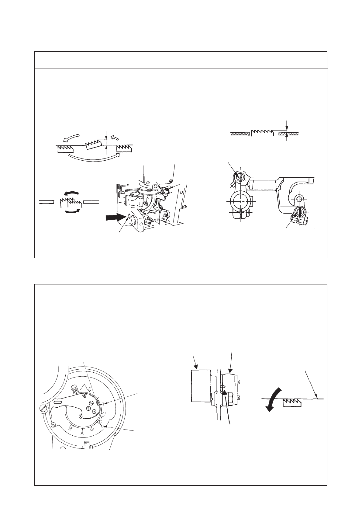
(1) Height and inclination of the feed dog .................................................................................................. 6
(2) Adjusting the feed timing ...................................................................................................................... 6
1) Adjusting the feed timing (Excluding A-SR).................................................................................... 6
2) Adjusting the feed timing (for A-SR only) ....................................................................................... 8
(3) Adjusting the feed amount.................................................................................................................. 10
1) Adjusting the feed amount (Excluding A-SR) ............................................................................... 10
2) Adjusting the feed amount (A-SR only) ........................................................................................12
(4) Position of the feed dog...................................................................................................................... 14
(5) Adjusting the slippage of materials (For A-SU and A-DU).................................................................. 16
(6) Adjusting the origin of the needle rocking motor ................................................................................ 18
(7) Adjusting the needle entry position (In terms of needle rocking direction) ......................................... 20
(8) Adjusting the needle entry position (In terms of longitudinal direction) .............................................. 20
(9) Adjusting the longitudinal play at the needle bar ................................................................................ 20
(10) Position of the needle bar connection guide..................................................................................... 22
(11) Height of the needle bar ................................................................................................................... 22
(12) Adjusting the needle-to-hook timing and the needle guard .............................................................. 24
(13) Position of the bobbin case stopper ................................................................................................. 26
(14) Orientation of the needle bar thread holder...................................................................................... 26
(15) Position of the thread tension ........................................................................................................... 28
(16) Position of the pre-tension................................................................................................................ 28
(17) Position of the thread take-up spring guard...................................................................................... 30
(18) Installing the thread take-up thread guide B..................................................................................... 30
(19) Installing the thread take-up ............................................................................................................. 30
(20) Installation of the presser foot .......................................................................................................... 32
(21) Installing and adjusting the bobbin winder unit................................................................................. 32
(22) Adjusting the amount of oil in the hook (A-SS/-7, A-SU/-7, A-SR) ................................................... 34
(23) Adjusting the thread trimming unit (Thread trimmer type only)......................................................... 36
(24) Initial position of the moving knife (Thread trimmer type only) ......................................................... 36
(25) Timing of the thread trimming cam (Thread trimmer type only)........................................................ 38
(26) Installing/removing the knife unit (Thread trimmer type only)........................................................... 38
(27) Stop position of the needle after thread trimming (Needle UP stop) ................................................ 38
(28) Clearance provided between the main shaft handwheel and the stator........................................... 40
(29) Position of the automatic reverse stitching magnet (Excluding A-SR) ............................................. 40
(30) Adjusting the thread tension releasing solenoid (Thread trimmer type only).................................... 40
(31) Adjusting the stitch length dial (Excluding A-SR) ............................................................................. 42
(32) Adjusting the lubrication mechanism (A-SS and A-SU, A-SR only) ................................................. 44
(33) Adjusting the position of the thread draw-out wire
(For the machine with thread trimmer only) ......................................................................................44
(34) Adjusting the stroke of the thread draw-out wire
(For the machine with thread trimmer only) ......................................................................................46
(35) Installing the wiper base (WB type only) .......................................................................................... 46
(36) Adjusting the wiper solenoid (WB type only) .................................................................................... 48
(37) Position of the wiper ......................................................................................................................... 48
1) WB type ........................................................................................................................................ 48
2) CB type......................................................................................................................................... 50

4. PROCEDURES OF DISASSEMBING/ASSEMBLING AND CAUTIONS .................... 52
(1) Adjusting and assembling of the gear box (large) .............................................................................. 52
(2) Replacing the motor ........................................................................................................................... 54
(3) Replacing the timing belt .................................................................................................................... 56
(4) Removing/installing the gear box cover.............................................................................................. 58
(5) Disassembling/assembling the needle bar support base shaft (asm.) ............................................... 58
(6) Adjusting/assembling the reverse feed control lever (A-SR only) ...................................................... 70
5. MAINTENANCE............................................................................................................ 76
(1) Changing procedure between single phase 100 to 120V and 3-phase 200 to 240V ......................... 76
(2) Replacing procedure of the printed circuit board................................................................................ 77
(3) Maintenance of the hook lubricating pipe oil filter............................................................................... 78
(4) Cleaning the cooling fan ..................................................................................................................... 79
(5) Applying the exclusive grease ............................................................................................................ 80
(6) Hook shaft gear .................................................................................................................................. 84
(7) Adjusting the needle rocking link ........................................................................................................ 85
(8) Lubricating to face plate section (A-SS and A-SU, A-SR only) .......................................................... 86
(9) Protruding amount of the hook shaft .................................................................................................. 88
(10) Adjusting the feed stepping motor unit (A-SR only).......................................................................... 88
(11) Draining of CB type .......................................................................................................................... 89
(12) Cleaning the dust bag of CB type..................................................................................................... 89
6. OPERATION PANEL.................................................................................................... 90
(1) Names of the respective sections....................................................................................................... 90
(2) Information.......................................................................................................................................... 92
(3) Matters that demand special attention regarding the operation panel, IP-100 ................................. 106
7. SPECIFICATIONS OF SC-915/916............................................................................ 107
8. FUNCTION SETTING PROCEDURE OF SC-915/916............................................... 107
(1) How to change over to the function setting mode ............................................................................ 107
9. FUNCTION SETTING LIST ........................................................................................ 111
10. DETAILED EXPLANATION OF SELECTION OF FUNCTIONS.............................. 115
11. EXTERNAL OUTPUT/INPUT CONNECTORS......................................................... 121
(1) Connector connection diagram......................................................................................................... 121
12. ERROR DISPLAY..................................................................................................... 122
(1) ERROR DISPLAY ............................................................................................................................ 122
(2) Error code list (Error display in panel) .............................................................................................. 123
(3) Warning list....................................................................................................................................... 126
13. SCREWS FOR ATTACHMENTS ............................................................................. 127
14. SPARE PARTS......................................................................................................... 127
15. OPTIONAL CORD .................................................................................................... 128
(1) Relay cord A asm. for standing machine (Part No. M9701351AA0) ................................................ 128
(2) Relay cord A asm. for DC24V (Part No. M9703351AA0) ................................................................. 129
16.TROUBLES AND CORRECTIVE MEASURES......................................................... 130
(1) With regard to lubrication.................................................................................................................. 130
(2) With regard to sewing....................................................................................................................... 132
(3) With regard to mechanical components ........................................................................................... 137
17. CONFIRMATION ...................................................................................................... 144
18. BLOCK DIAGRAM ................................................................................................... 145
(1) Block diagram A (for SC-915)........................................................................................................... 145
(2) Block diagram B (for SC-916)........................................................................................................... 146
(3) Operation panel block diagram......................................................................................................... 147
19. DRAWING OF TABLE.............................................................................................. 148
CUSTOM PATTERN NEEDLE ENTRY POSITION DATA SHEET ....................................................... 149

−1−
LZ-2290A-SU / -7
4,500 rpm (*1)
2.5mm/2.5 mm (*3)
(Stepless fine adjustment)
1.4mm
LZ-2290A-SS / -7
5,000 rpm (*1)
5 mm/4 mm (*3)
(Stepless fine adjustment)
1.2 mm
LZ-2290A-DS / -7
5mm/4 mm (*3)
(Stepless fine adjustment)
1.2 mm
Light- to medium-weight materials
10 mm (*2)
8 kinds 14 patterns
(Custom pattern : 500 stitches, 20 kinds can be stored.)
SCHMETZ 438, ORGAN DPX5 : #65 to #90
178 mmX517 mm
4,000 rpm (Excluding a certain territory of export)
33.4 mm
Built-in in the upper face of machine head type (with bobbin thread retaining plate)
Electromagnetic front-wiping system (WB), electromagnetic side-wiping system (CB)
Built-in electromagnetic system
5.5 mm
10 mm
6 to 6.5 mm
Direct drive system (compact AC servo motor)
Timing belt system
Rated output 450W
3-phase 200 to 240V, Single phase 100 to 120V
DC34V
Presser foot micro-lifting screw is provided as standard.
1. AK-121 (Auto-lifter : Part No. : GAKA21000B0)
2. Exclusive grease tube for maintenance 10g (JUKI grease A Part No. : 40006323)
3. Exclusive grease can for maintenance 500g (Part No. : 23640204)
4. Touch-back kit asm. (Part No. ; 40010795) ... Other than WB, CB, OB, A-SR)
5. Optional switch kit (Part No. ; 40003640)
LZ-2290A-DU / -7
2.5mm/2.5 mm (*3)
(Stepless fine adjustment)
1.4mm
1. SPECIFICATIONS
* 1 : The sewing speed is regulated in accordance with zigzag width (A-SR : zigzag width and feed amount).
* 2 :Zigzag width is regulated to 8 mm at the time of delivery. (Max. zigzag width of all machines is 10 mm.)
* 3 : Normal and reverse feed amounts are regulated to 2 mm at the time of delivery.
Model
Application
Max. sewing speed
Max. zigzag width
Max. feed amount
(Normal/reverse)
Stitch pattern
Needle
Dimension of the bed
Number of revolution
of resistor pack
Needle bar stroke
Bobbin winder
Wiper
Automatic reverse
stitching device
Lubrication
Lift of the presser foot
(by hand lifter)
Lift of the presser foot
(by knee lifter)
Lift of the presser foot
(by AK auto-lifter)
Kind of the hook
(Part No.)
Bobbin case (asm.)
Heightofthefeed dog (standard)
Lubricationoftheface
plate section
Drive system
Transmissionfunction
Motor output
Operating power
Solenoid drive power
Additional function
Major optional
devices
1
2
3
4
5
6
7
8
9
10
11
12
13
14
15
16
17
18
19
20
21
22
23
24
25
26
27
Lubrication system to oil tank for hook
lubrication
JUKI New Defrix Oil No. 1 is used.
(Equivalent to ISO VG7)
Plunger pump is employed.
22525877
40003598 (with idle-prevention spring)
Minute quantity lubrication by oil wick
Full non-lubrication
23557259 (Non-lubrication hook)
Non-lubrication
4,000 rpm (*1)
LZ-2290A-SR-7
5,000rpm (*1)
5mm/5 mm
(0.1 adjustment by electronic control)
14 kinds 20 patterns
Stepping motor
control
Lubrication system to
oil tank for hook
lubrication
JUKI New Defrix Oil
No. 1 is used.
(Equivalent to ISO
VG7)
Plunger pump is
employed.
22525877
40003598
(with idle-
prevention spring)
1.2 mm
Minute quantity
lubrication by oil wick
(1) Specifications of the machine head
40003609 (with idle-prevention spring)

−2−
(2) Stitch pattern table
Name of pattern Stitch
pattern
Blind stitch (right)
Blind stitch (left)
Custom pattern
T stitch (left)
T stitch (right)
Pattern 1
Pattern 2 (fagoting)
Pattern 3
Pattern 4
Standard
scallop
Crescent
scallop
Equal-width
scallop
Equal-width
scallop
Standard
scallop
Crescent
scallop
Equal-width
scallop
Equal-width
scallop
Number of stitches
for pattern
Max.zigzag
width Remarks
1
2
4
6
24
12
24
12
2 + a
――
3
6
a
{
a
{
Straight stitch
Standard zigzag stitch
2-step zigzag stitch
3-step zigzag stitch
Scallop
(right)
Scallop
(left)
10
――
500

−3−
(3) Function list
Sewing
Straight stitch
Standard
2-step
3-step
Blind stitch
Scallop
Custom
T stitch
Pattern 1
Pattern 2
(fagoting)
Pattern 3
Pattern 4
Free
Overlapped
Program
Pattern
Continuous
Cycle
Max. number
of steps
Max. number
of stitches in each step
Max. number of registers
that can be performed
Max. number
of stitches
Free
stitching Overlapped
stitching Program
stitching Conden-
sation Conden-
sation
custom
Custom
pattern
(Internal
memory)
Custom
pattern
(Smart
media)
Zigzag
width and
stitch base
line setting
Pattern
register Continuous
stitching
register
Cycle
stitching
register
9
19
20
500
10,000
64
Start 20
End 20
500
20
10,000
500
999
499,500
99
20
500
10
10,000
20
500
10
10,000

−4−
2. NAME OF EACH COMPONENT
1 Needle thread draw-out device
(Thread trimmer type only)
2 Wiper switch (WB/CB type)
3 Thread take-up cover
4 Finger guard
5 Thread tension controller
6 Control box
(4) Cautions in operation
1) Be sure to drain oil in the oil tank and attach the air vent cap (red rubber cap) supplied with the machine to the air
vent (golden bushing) located on the side face of the machine bed when transporting the sewing machine.
2) In the case where placing A-SS or A-SU, A-SR type machine on a stand or the like before setting the machine to the
machine table, to protect the oil tank from damage, take car if there is any protruding object under the stand or the like.
3)
Be sure to securely set the connector of the safety switch to the control box to prevent accidents at the time of maintenance.
4) Oil is kept in the gear box for lubrication. It is not necessary to replace the oil. Do not remove the gear box cover
except when it is necessary.
* When the box cover has been removed, it is necessary to replace the packing.
5) Be sure to operate the sewing machine with the bobbin case removed when making the sewing machine run idle.
If the bobbin thread is in the bobbin case, the thread protrudes from the bobbin case and is entangled in the hook
race or the hook shaft. As a result, the trouble will be caused.
1
2
3
4
5
6
7
8
9
!0
!1
!22
!3
!5
!6
!77
!88
@0
!9
!4
!44 Bobbin winder
!5 Tension controller No. 1
!6 Thread stand
!77 Oiling inlet
(Excluding dry-head type)
!88 Reverse feed stitching lever
!9 Mirror switch
@0 Handwheel
7 Pedal
8 Knee lifter lever
9 Power switch
!0 TB switch
!11 Stitchlengthdial(Excluding A-SRtype)
!22 Condensationdial(ExcludingA-SRtype)
!33 Operation panel

−5−
1Needle thread draw-out device (Thread trimmer type only)
This device draws out needle thread at the time of thread trimming.
2Wiper switch (WB/CB type)
This switch is used to wipe needle thread after thread trimming from the cloth by means of the wiper
signal which is output from the PSC box.
3Thread take-up cover
This is a cover to protect the human body from the contact with the thread take-up.
4Finger guard
This is a guard to protect the human body (mainly fingers) from the contact with needle.
5Thread tension controller
6Control box
This box contains circuit to control sewing machine and motor, output circuits to activate respective
outputs (thread trimming solenoid, reverse feed stitching solenoid, etc.), pedal sensor to detect pedal
action, and power circuit to activate respective functions.
7Pedal
This pedal performs sewing machine speed control, thread trimming action, presser lifting action (for
AK121 only), etc. by operation of depressing the front part of pedal or the back part of pedal.
8Knee lifter lever
9Power switch
This is the power switch for motor, PSC, operation panel, etc.
!0 TB switch
This is an operation switch to perform reverse feed stitching by means of the TB switch.
!1 Stitch length dial (Excluding A-SR type)
This is a dial to adjust normal feed amount.
!2 Condensation dial (Excluding A-SR type)
This is a dial to adjust reverse feed amount.)
!3 Operation panel
This panel is used for setting automatic reverse feed stitching, pattern stitching, zigzag width, etc.
!4 Bobbin winder
This is a bobbin winder which is built in the machine head.
!5 Tension controller No. 1
!6 Thread stand
!7 Oiling inlet (For A-SS, A-SU and A-SR only)
This is the oiling inlet for hook lubrication. (For A-SS and A-SU, A-SR only)
!8 Reverse feed stitching lever
!9 Mirror switch
This is an operation switch to inverse scallop pattern or custom pattern by means of the mirror switch.
@0 Handwheel

−6−
3. STANDARD ADJUSTMENT
(1) Height and inclination of the feed dog
Standard Adjustment
Standard Adjustment
A B
Standard height : 1.2 mm : LZ-2290A-SS,
LZ-229A-DS, LZ-2290A-SR
: 1.4 mm : LZ-2290A-SU, LZ-2290A-DU
Inclination : The feed dog should be almost leveled
when the top surface of the ascending feed
dog is flush with the top surface of the
throat plate. (A-SS, A-DS, A-SR)
Reference for the height and inclination of the
feed dog
™When the respective marker dots are
leveled, the height is 1.2 mm and the
inclination is leveled. (A-SS, A-DS, A-SR)
Timing mark J
engraved on
face plate
Feed rocker
cam
Feed
rocker rod
Alignment of
timing marks
Timing mark I
engraved on
face plate
Marker line
engraved on
thread take-
up
1.2 mm
Throat plate
Feed dog
Hole for
screwdriver
Top suface of
throat plate
Comes down.
1.2 mm
LeveledLeveled
Operator’s
side Position of marker dot
(Inclination)
Position of marker dot
(Height)
1
2
3
A
(2) Adjusting the feed timing
1) Adjusting the feed timing (Excluding A-SR)

−7−
Adjustment Procedures Results of Improper Adjustment
1) Set the feed amount to 0 mm. (Feed amount of the machines other
than A-SR type is regulated to max. 2 mm at the time of delivery.)
2) Adjusting the height of the feed dog
Loosen screw 1and adjust the height of the feed dog by turning feed
driving link shaft 2.
3) Adjusting the inclination of the feed dog
Loosen screw 3. Put a screwdriver through the hole for the screwdriver
and adjust the inclination of the feed dog by turning the feed rocker
shaft with the screwdriver.
(Caution) 1. If the feed rocker shaft is not pressed in the direction A
(a) during the adjustment procedure, there will be a
play at the feed bar or washer will come off. So, be sure
to adjust the feed dog with the feed rocker shaft pressed
in the direction A (a).
2. Check to be sure that the feed dog is leveled with the
feed amount currently used when the top surface of
the ascending feed dog is flush with the top surface of
the throat plate.
3. For the adjustment of slippage of materials for A-SU
and A-DU, refer to (5) Adjusting the slippage of materials
and adjusting the feed timing.
™Perform the adjustment of the
inclination of the feed dog according
to the sewing process.
(Example)
™When the feed force is required in
such a process of tape attaching or
the like :
Adjust so that this side of the feed
dog is raised.
™When using the slippery material in
such a process of attaching a facing
of girdle :
Adjust so that the feed dog should
be leveled.
A. Adjusting procedure by removing the gear box cover (A-SS,A-DS)
1) Remove the gear box cover. (Refer to the item 4-(1).)
2) Adjust the marker line engraved on the thread take-up to the timing
mark I engraved on the face plate.
3) Set the feed amount to 0 mm.
4) In the aforementioned state, loosen the setscrew in the hook driving
shaft sprocket and adjust the timing mark engraved on the feed rocker
cam to the timing mark engraved on the feed rocker rod.
(Caution) In this case, the hook timing (thread trimming timing for the
machine equipped with a thread trimmer) changes. Be sure to perform
re-adjustment.)
B. Adjusting procedure with the gear box cover attached (For fine
adjustment) (A-SS,A-DS)
1) Set the feed amount to "0" mm.
2) Adjust the marker line engraved on the thread take-up to marker line
J engraved on the face plate.
3) In the aforementioned state, loosen the setscrew in the hook driving
shaft sprocket. Now, turn the hook driving shaft to adjust so that the
feed dog comes down. Adjust so that the top surface of the feed dog is
aligned with the top surface of the throat plate when the feed dog comes
down.
*There is a slight inclination at the feed dog. Adjust the feed dog so that
“0” to 6 teeth come out from the top surface of the throat plate.
(Caution) After the aforementioned adjustment, “hook timing” and
further “thread trimming cam timing” for the machine equipped with a
thread trimmer will change. Be sure to re-adjust them properly.
™For the adjustment of A-DU and A-
SU, refer to (5) Adjusting the
slippage of materials and adjusting
the feed timing.
™For the adjustment of A-SR, refer to
2) Adjusting the feed timing.

−8−
2) Adjusting the feed timing (for A-SR only)
Standard Adjustment
1
2
3
4
5
6
7
Mark on feed
adjustor
8
3
5
5
Engraved marker
dot on bed
Feed rocker
cam
Feed
rocker rod
Alignment of
timing marks
Top suface of
throat plate
Comes down.
A
B
Timing mark on
face plate G
I
Engraved marker line
on thread take-up
Timing mark on
face plate F

−9−
Adjustment Procedures Results of Improper Adjustment
A. Procedure by removing the gear box large lid (Standard
adjustment) (A-SR)
1) Remove the gear box large lid. (Refer to 4-(1).)
2) Adjust the engraved marker line on the thread take-up to timing
mark G on the face plate.
3) Align the timing mark on the feed adjustor with the engraved
marker dot on the machine bed.
<<Confirmation of the standard timing>>
4) Timing mark of the feed rocker cam aligns with that of the feed
rocker rod. ... Standard state
Standard assembling adjustment is described below.
5) When they do not align with each other, loosen two setscrews
8in the hook driving shaft sprocket, and it is necessary to
align the timing mark of the feed rocker cam with that of the
feed rocker rod.
6) Tilt the machine head, remove feed stepping motor connector
1, and remove feed lever spring 2from the spring bracket.
* When removing feed lever spring 2, perform the work using the
radio pincers or the like.
7) Loosen two setscrews 3in the feed stepping motor link C and
draw out feed link shaft 4to the right-hand side.
8) Remove three setscrews 5in the feed stepping motor unit.
9) When removing the feed stepping motor unit, remove oil pipe
7from oil pipe guide 6.
10) In the state of 3), loosen two setscrews 8in the hook driving
shaft sprocket, and adjust the timing mark on the feed rocker
cam to that on the feed rocker rod.
11) When re-assembling the feed stepping motor unit, refer to 3-
(3)-2) Adjusting the feed amount.
B. Procedure with the gear box large lid installed (For fine
adjustment) (A-SR)
It is possible to check standard timing without opening the gear
box large lid.
1) Adjust the engraved marker line on the thread take-up to timing
mark F on the face plate.
2) It is the standard timing that the top surface of feed dog almost
aligns with the top surface of throat plate when the feed dog
sinks. However, the height of feed dog is 1.2 mm at the time of
standard delivery.
3) Align the timing mark on the feed adjustor with the engraved
marker dot on the machine bed. (When feed amount is “0”)
4) When they do not align with each other, loosen two setscrews
8in the hook driving shaft sprocket and adjust the timing.
(For the adjustment procedure, refer to the aforementioned
items 1) through 6).
* Adjusting the feed timing (Common to A. and B.)
By performing the feed timing adjustment, stitch tightness
changes and sewing quality is improved according to the
process.
™When oil pipe guide6is forcibly
drawn, the oil pipe comes off or
damaged. As a result, oil
leakage will be caused.
™When changing the feed timing
other than the standard one, it
is easy to adjust when the
standard state is made a basis.
* When changing the feed timing
other than the standard one, and
sewing patterns that perform
normal/reverse feed motion (T
stitch, custom pattern, etc.),
needle may bend according to
the feed amount (needle snaps).
In this case, change the feed
timing from the panel and
compensate.
™Timing mark on the feed adjustor
is the inside mark. (Common to
A. and B.)

−10 −
(3) Adjusting the feed amount
Standard Adjustment
LZ-2290A-SS, A-DS
Feed crank stud Timing mark
Normal feed amount
regulation metal fitting Feed spring hook
Feed converting
arm A (asm.)
Feed adjusting link
Reverse feed amount
regulation metal fitting
1
2
3
1) Adjusting the feed amount (Excluding A-SR)
LZ-2290A-SU, A-DU

−11 −
Adjustment Procedures Results of Improper Adjustment
[Feed “0” adjustment]
1) Set the stitch length dial at “0”.
2) Loosen screw 1, and align the timing mark on the feed crank stud
with that on the feed crank stud support.
(The position of the timing mark differs with models.)Insert a sheet of
paper between the throat plate and the presser foot, turn the
handwheel by hand and check that the needle entry points are the
same. If the points are not the same, perform again fine adjustment.
(Fine adjustment is necessary since the marks are standard.)
3) When loosening screw 1, confirm that there is no axial play at the
feed converting arm A (asm.) and tighten screw 1.
[Normal feed adjustment]
4) Set the stitch length dial at the maximum value of the gauge to be
used.
* Normal feed is regulated to 2 mm at the time of delivery.
5) Loosen screw 2, make the feed adjusting link come in contact with
the screw and tighten screw 2.
[Reverse feed adjustment]
6) Loosen screw 3, pushing the feed lever down to make the sewing
machine enter the reverse feed stitching mode, press reverse feed
amount regulation metal fitting against the projecting section of the
reverse feed adjusting link B. Now, tighten screw 3. (Set the
condensation stitch length adjusting dial to the maximum value on
the scale.)
* Reverse feed is regulated to 2 mm at the time of delivery.
7) To decrease the reverse feed stitching length for fastening stitching,
use the condensation stitching function. (Refer to “Adjusting the
condensation stitching mechanism” in the Instruction Manual for the
LZ-2290A Series.)
8) When the ratio of sewing length (as many as 10 stitches) of normal
and reverse feed is approximately 90% in case of straight stitch feed
amount of 2 mm, the adjustment is OK.
™If the timing marks are not aligned
with each other, the actual feed
amount will be different from the
feed amount specified on the stitch
length dial.
™If the timing marks greatly separate
from each other, the normal or
reverse feed amount will be
increased causing the feed dog to
come in contact with thread
trimming counter knife. (In case of
thread trimming)
Max. normal feed amount
of the mechanism LZ-2290A-SS, A-DS=5 mm
LZ-2290A-SU, A-DU=2.5 mm
Max. reverse feed amount
of the mechanism LZ-2290A-SS, A-DS=4 mm
LZ-2290A-SU, A-DU=2.5 mm
Normal feed →large
Reverse feed →small
Nomal feed →small
Reverse feed →large

−12 −
2) Adjusting the feed amount (A-SR only)
Standard Adjustment
4
4
4
5
Normal feed amount : 0
Extreme left end
of speed variable
resistor
Straight stitching
12
3
1
3
2
Feed stepping motor unit
To smoothly rotate
6
Less
than
700g by
spring
balancer
is the
srandard.

−13 −
[Feed 0 adjustment]
For the adjustment of feed 0 position, perform fine adjustment of the
direction of rotation of feed adjustor 1.
1) Tilt the machine head and loosen two setscrews 2in the stepping
motor link C.
2) Adjust feed link shaft 3to the slippage amount of feed using a slotted
screwdriver and temporarily tighten two setscrews 2in the stepping
motor link C.
* Feed link shaft 3consists of eccenric pin.
3) Return the machine head to the home position, turn ON the power, set
the operation panel to straight stitching, and set normal feed amount
to “0”.
* Set the speed variable resistor of operation panel to the extreme left
end and set the sewing speed to 200 rpm.
4) Insert a sheet of paper under the presser foot and depress the pedal
to operate the sewing machine.
At this time, check the needle entry on the paper to check that feed
amount becomes “0”.
5) When feed amount is “0”, tilt the sewing machine head after turning
OFF the power and securely tighten two setscrews 2in the stepping
motor link C.
After securely tightening the setscrews, check that feed adjustor 1
smoothly moves with the presser foot lifted.
When the feed amount does not become “0”, turn OFF the power
again and repeat the work of steps 1) and 2).
[Feed 0 adjustment] : When feed amount does not become “0” by
adjusting feed link shaft 3only.
1) Loosen three fixing screws 4in the feed stepping motor unit and
perform the vertical adjustment of feed stepping motor unit 5.
2) After the adjustment, check that feed adjustor link 6smoothly moves
with the presser foot lifted.
3) The standard that feed adjustor link 6smoothly moves is the feed
mechanism torque (less than 700g by the spring balancer) before
setting the feed stepping motor unit. (Be sure to perform the centering
work so that the torque is less than 1,000g.)
[Normal/reverse feed amount control]
1) Input max. feed amount limitation value of normal/reverse feed with
the information of operation panel
* For the information operation, refer to Instruction Manual.
* Normal/reverse feed amount has been factory-set to the standard
adjustment value of JUKI standard delivery gauge (Part No. 40018430
... max. feed amount of normal/reverse stitching is 5 mm).
There are cases where the feed amount varies from the actual input
value in accordance with the material used or kind of gauge. Then
perform the input compensation.
Adjustment Procedures Results of Improper Adjustment
™Start the work of the feed amount
“0” adjustment after performing 3-
(2)-2) Adjusting the feed timing (A-
SR only).
™When there is a torque, one-sided
worn-out of feed link or step-out of
feed stepping motor 5will be
caused.
™When there is a torque, one-sided
worn-out of feed link or step-out of
feed stepping motor 5will be
caused.
Normal feed
small
Reverse feed
large
Normal feed
large
Reverse feed
small

−14 −
(4) Position of the feed dog
Standard Adjustment
Condition : Feed amount : maximum
Feed bar
AB
12
1
A=B

−15 −
Adjustment Procedures Results of Improper Adjustment
™When feed amount is not regulated
by the position of feed dog or normal
feed amount regulation metal fitting,
feed dog and throat plate interferes
with each other.
™When feed amount is not regulated
by the position of feed dog or
information input, feed dog and
throat plate interferes with each
other.
[A-SS/-7, A-SU/-7, A-DS/-7, A-DU/-7]
1) Adjust the stitch length dial to the maximum feed amount the feed
dog to be used.
*Feed amount of both normal feed and reverse feed is regulated to 2
mm at the time of delivery from the factory.
The maximum feed amount of the feed dog at the time of delivery is 2
mm. (Feed dog part No. : 22581508)
[A-SR only]
1) Adjust the stitch length dial to the maximum feed amount the feed
dog to be used.
* Feed amount of normal/reverse feed has been factory-adjusted to 5
mm at the time of delivery from the factory. (Feed dog Part No. :
40018430)
[Common to A-SS/-7, A-SU/-7, A-DS/-7, A-DU/-7 and A-SR]
2) Turn the handwheel, and fix the feed dog so that the clearances in
front and rear are the same at the position where the feed dog does
not come in contact with the throat plate. (A = B)
3) In the case where the gear box (large) cover is not opened, loosen
setscrews 1in the feed bar crank to adjust the position.
4) In the case where the gear box (large) cover is opened, loosen
setscrew 2in the feed rocker shaft crank to adjust the position.

−16 −
(5) Adjusting the slippage of materials (For A-SU and A-DU)
Standard Adjustment
1.4mm
θ
1.4 mm
θ
θ
Standard state of engraved marker
dot of vertical feed link shaft
Standard height of feed dog
Operator’s
side
Sewing direction
Upper material
Lower material
Minus slippage
of material
Upper material
Lower material
Upper material
Lower material
“0” slippage
of material
Plus slippage
of material
Standard position
1
23
23
3
3
3
Engraved marker line
on thread take-up Timing mark on
face plate G
Horizontal feed cam Horizontal feed rod
Alignment of timing marks
I
This manual suits for next models
4
Table of contents
Other JUKI Sewing Machine manuals

JUKI
JUKI LU-1510N-7 Quick start guide

JUKI
JUKI DU-1481 Series User manual

JUKI
JUKI MO-735 User manual

JUKI
JUKI SC-920 User manual

JUKI
JUKI DLM-5200N User manual

JUKI
JUKI HZL-E61 User manual

JUKI
JUKI LU-2810-6 User manual

JUKI
JUKI DDL-9000B User manual

JUKI
JUKI DLN-9010A-SH User manual

JUKI
JUKI LU-2210N-7 User manual

JUKI
JUKI AMS-210EN/IP-420 User manual

JUKI
JUKI TL-98Q User manual

JUKI
JUKI HZL-27Z User manual

JUKI
JUKI TSU-471 Quick start guide

JUKI
JUKI LU-2810-6 User manual

JUKI
JUKI MCS-1500 User manual

JUKI
JUKI LZ-271 User manual

JUKI
JUKI MF-7000 Series Quick start guide

JUKI
JUKI LK-1900A Quick start guide

JUKI
JUKI LK-1900S Series User manual