JUKI LU-1520N-7 User manual

– 1 –
No.
1
2
3
4
5
6
7
8
9
10
11
12
13
14
15
16
17
18
19
20
21
22
23
24
25
26
1. SPECIFICATIONS
Item
Model
Model name
Application
Sewing speed
Needle
Thread possible to be
sewn
Thread possible to be
trimmed
Stitch length
Presser foot lift
Stitch length adjusting
mechanism
Reverse stitch adjusting
method
Thread take-up
Needle bar stroke
Alternate foot stroke
Hook
Feed mechanism
Top and bottom feed
actuation mechanism
Thread trimming
mechanism
Needle thread roll-in
mechanism
Automatic presser foot
lifter mechanism
Lubrication
Lubricating oil
Cylinder bed diameter
Free space for sewing
Size of handwheel
Motor
Specifications
LU-1520N-7
1-needle, unison feed, lockstitch machine with automatic thread trimmer
(Needle thread roll-in and shorter-thread remaining type)
For heavy-weight materials
Max. 3,000 rpm
SCHMETZ 135 X 17 Nm 125 to 180 Standard : Nm 160
#30 to #5
#30 to #5
Max. 9 mm (normal/reverse feed)
Hand lifter : 9 mm Knee lifter : 16 mm
By dial
Air cylinder type (with touch-back switch)
Slide thread take-up
36 mm
1 mm to 6.5 mm Alternate foot stroke adjusted by dial
Full-rotary vertical-axis 2-fold hook (Latch type)
Ellipse feed
Timing belt
Air cylinder + cam-driven scissors type
Threading by air cylinder + thread presser type
Air cylinder type
Automatic lubrication (partially by manual)
JUKI New Defrix Oil No. 2
517 mm x 178 mm
255 mm x 99 mm
V belt effective diameter : ø93.3 mm Outer diameter : ø160 mm
SC-380

– 2 –
Model DimennsionA
LU-1520N-7 9±0.1mm
A
A
aa’
Standard Adjustment
Standard Adjustment
(2) Longitudinal position of the feed dog
2. STANDARD ADJUSTMENT
(1) Needle entry position
1
2
3
2
60 mm
Top surface of
throat plate
Conditions
• Needle bar at lowest dead point
• Feed amount : 0 mm
Conditions
• Needle bar at lowest dead point
• Feed amount : 0 mm
A = Clearance between the feed dog and the throat plate
when the feed amount is maximum and the feed dog
travels fully to the front
1
3
a=a’ A=1.8mm

– 3 –
Adjustment Procedures Results of Improper Adjustment
1. Set the stitch dial to “0”.
2. Turn the handwheel to bring the needle bar to the lowest dead
point of its stroke.
3. Loosen clamping screw 1in the needle bar rocking rear arm.
4. In the state that the presser foot is raised, adjust the clearance
between presser bar 2and walking bar 3to dimension A at
the position where the distance from the top surface of the
throat plate to the presser foot is 60 mm. Then securely tighten
clamping screw 1in the needle bar rocking rear arm.
(Caution) Tighten the screw so that the needle bar rocking
shaft has no thrust play.
™Stitch skipping or needle
breakage will result.
™Poorly tensed stitches will result.
™The throat plate comes in
contact with the feed dog and
contacting noise occurs and the
throat plate or the feed dog may
be damaged.
™Irregular stitches may result.
1. Set the stitch dial to “0 ”.
2. Turn the handwheel to bring the needle bar to the lowest dead
point of its stroke.
3. Loosen clamping screw 3in the feed rocker.
4. Move the feed base and adjust so that needle 1enters the
center of the needle hole in feed dog 2. Then securely tighten
clamping screw 3in the feed rocker. (a = a’)
Checking method
1. Set the stitch dial to the maximum.
2. Turn the handwheel and ckeck that clearance A in terms of the
groove of the throat plate is 1.8 mm when feed dog 2travels
fully to the front.
In addition, make sure that feed dog 2does not come in contact
with the throat plate at the position where the feed dog travels
fully to the rear.
(Standard)
When the feed amount is maximum, A = approximately 1.8
mm.

– 4 –
Standard Adjustment
Standard Adjustment
(4) Height of the feed dog
(3) Lateral position of the feed dog
1
2
1
2
34
aa’
AB
A
Conditions
• Needle bar at lowest dead point
• Feed amount : 0 mm
Conditions
• Feed amount : 0 mm
• Height of feed dog is maximum.
Model Dimension A
LU-1520N-7 0.4 to 0.5 mm
Adjust the position to almost A = B.
3
a=a’

– 5 –
Adjustment Procedures Results of Improper Adjustment
1. Set the stitch dial to “0”.
2. Turn the handwheel to bring the needle bar to the lowest dead
point of its stroke.
3. Loosen clamping screw 3in the feed rocker.
4. Move the feed base and adjust so that needle 1enters the
center of the needle hole in feed dog 2. Then securely tighten
clamping screw 3in the feed rocker. (a = a')
In addition, adjust the lateral clearances of feed dog 2in terms
of the window of throat plate to almost equal values. (A = B)
When the height of the feed dog is
higher than the specified value :
™Stitch pitch becomes larger than
the scale of the feed dial.
™Balloon stitches will result.
™Return of sewing product will
occur.
™Feed dog comes in contact with
the knife, and the knife and the
feed dog may be damaged.
When the height of the feed dog is
lower than the specified value :
™Stitch pitch becomes smaller
than the scale of the feed dial.
™Feed force will be deteriorated.
™Stitch skipping or thread
breakage will result.
™Poorlytensedstitcheswillresult.
™Needle breakage will result.
1. Set the stitch dial to “0”.
2. Turn the handwheel to bring the height of the feed dog to the
maximum.
(Bring the needle bar to the lowest dead point of its stroke.)
3. Loosen setscrew 1in the feed bar slide fork, move feed bar
slide fork 2up or dowm and adjust feed dog 3from top surface
4of the throat plate (center section) to the dimension A. Then
securely tighten setscrew 1in the feed bar slide fork.

– 6 –
Standard Adjustment
Standard Adjustment
(6) Adjusting the inner hook guide
(5) Height of the hook
Conditions : When the inner hook guide travels to its back end.
: Press the inner hook stopper to the groove in the throat plate.
1
2
3
4
3
0.1 to 0.2 mm
B
Hook stopper section
4
1±0.1 mm
1
2
3
To come in close contact
with each other

– 7 –
Adjustment Procedures Results of Improper Adjustment
1. Loosen two setscrews 1in the screw gear (small).
2. Draw out hook 2in the direction of the arrow. (At this time,
bring No. 1 screw of setscrews 1to the front of the operator.)
3. Replace thrust plate 3and adjust so that a clearance of
1±0.1mm is provided between throat plate 4and the top
surface of hook stopper section of hook 2.
(For the kind of thrust plate 3, refer to “5. Selective parts and
consumable parts”.)
4. Assemble hook 2so that the notched section of the shaft of
hook2comes to the front of the operator and tighten setscrews
1. (The notched section should align with No. 1 screw of
setscrews 1.)
When the clearance is larger than
the specified value :
™Loose stitches or thread
breakage will result.
When the clrarance is smaller than
the specified value :
™Inner hook or inner hook guide
may be damaged.
™Stitch skipping or thread
breakage will result.
™Needle breakage will result.
™Irregular stitches will result.
1. Turn the handwheel to bring inner hook guide 1to its back
end position.
2. Turn inner hook 2in the reverse direction of rotation of the
hook (in the direction of arrow mark A) and fit the inner hook
stopper to the inner hook stopping section in throat plate 3.
3. Loosen setscrew 4in the inner hook guide arm and adjust the
clearance between inner hook guide 1and the protruding
section of inner hook 2to 0.1 to 0.2 mm.
4. After the adjustment, securely tighten setscrew 4in the inner
hook guide arm.

– 8 –
Standard Adjustment
(7) Needle-to-hook timing
1
2
Model Dimension A
LU-1520N-7 58.7 mm
Conditions : Feed amount : 0 mm
: Needle bar rises from the lowest dead point
of its stroke.
6
Model Dimension B Dimension C Dimension D
LU-1520N-7 2.3±0.2 mm 1.5±0.2 mm 0.05 to 0.1 mm
A
4
4
8
3
5
6
7
5
Standard of dimension B : Engraved marker line on the lower side of needle bar
BC
D
0.1 to 0.2 mm
Standard : Engraved marker line on the upper
side of needle bar

– 9 –
Adjustment Procedures Results of Improper Adjustment
™Stitch skipping or thread
breakage will result.
™Loose stitches will result.
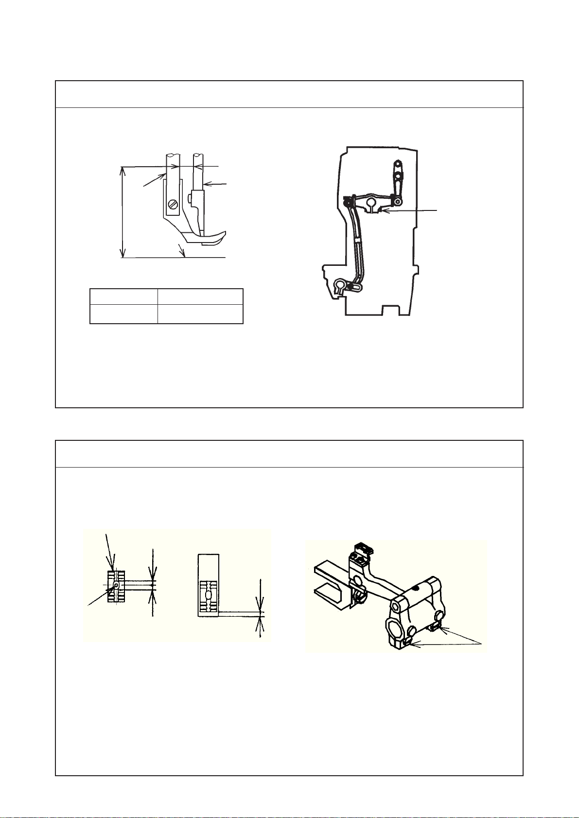
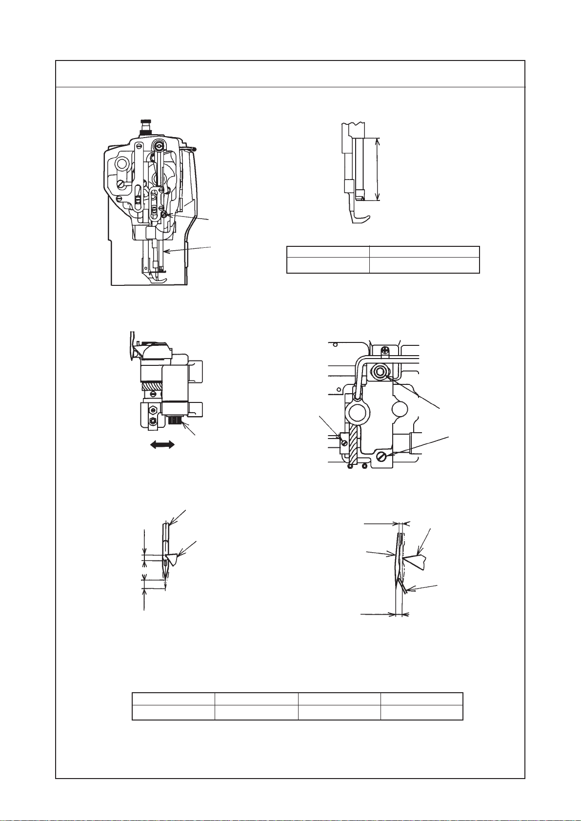
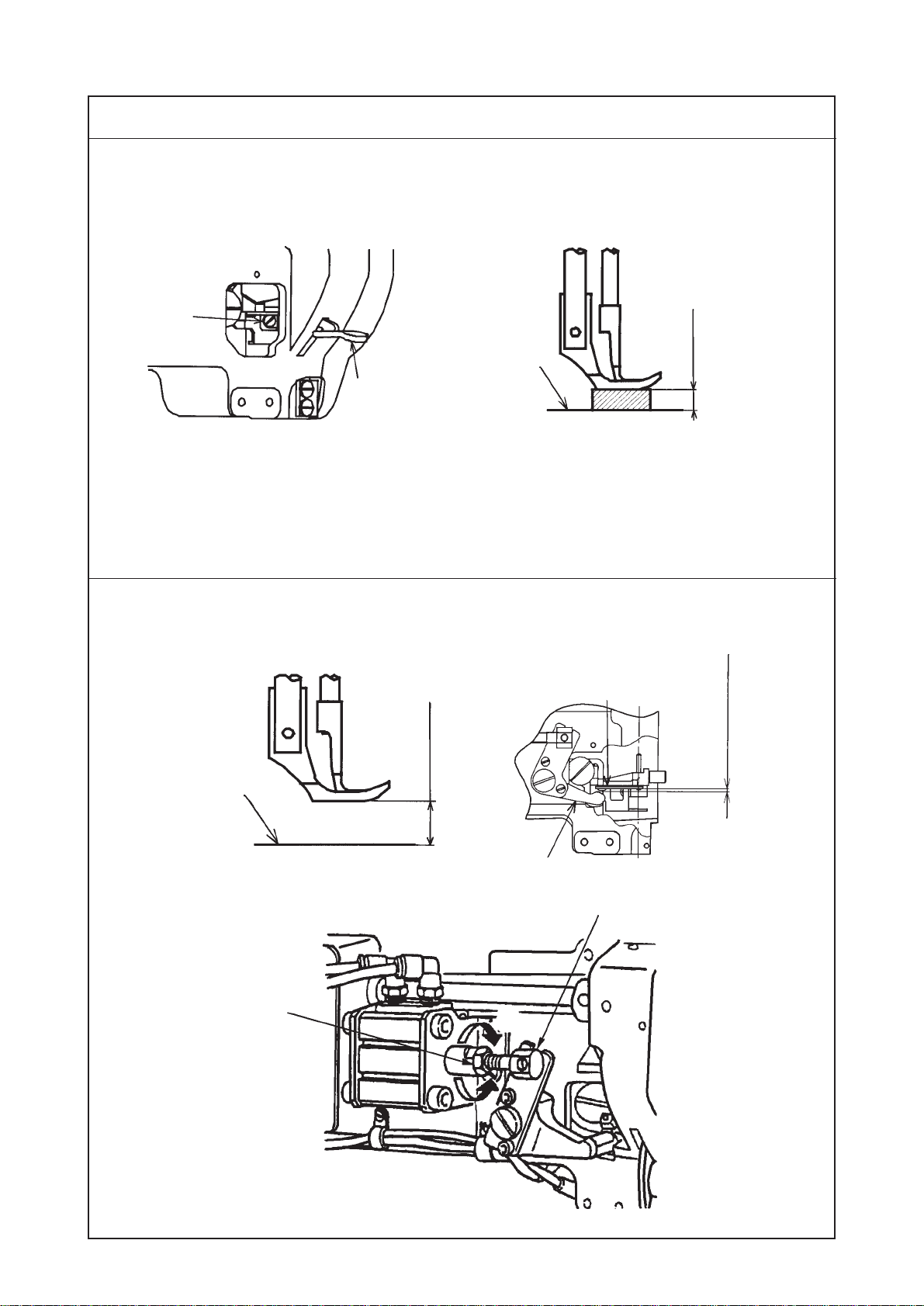
1) Standard of the lowest dead point of the needle bar
1. Set the stitch dial to “0”.
2. Turn the handwheel to bring needle bar 1to the lowest dead
point of its stroke.
3. Loosen the setscrew in the face plate to remove the face plate.
4. Loosen clamping screw 2in the needle bar holder. At this
time, loosen the screw to such an extent that needle bar 1
moves up and down by hand since needle bar 1drops if the
screw is fully loosened.
5. Adjust the distance from the lower end of needle bar frame to
the lower end of the needle bar to dimension A. Then tighten
clamping screw 2in the needle bar holder.
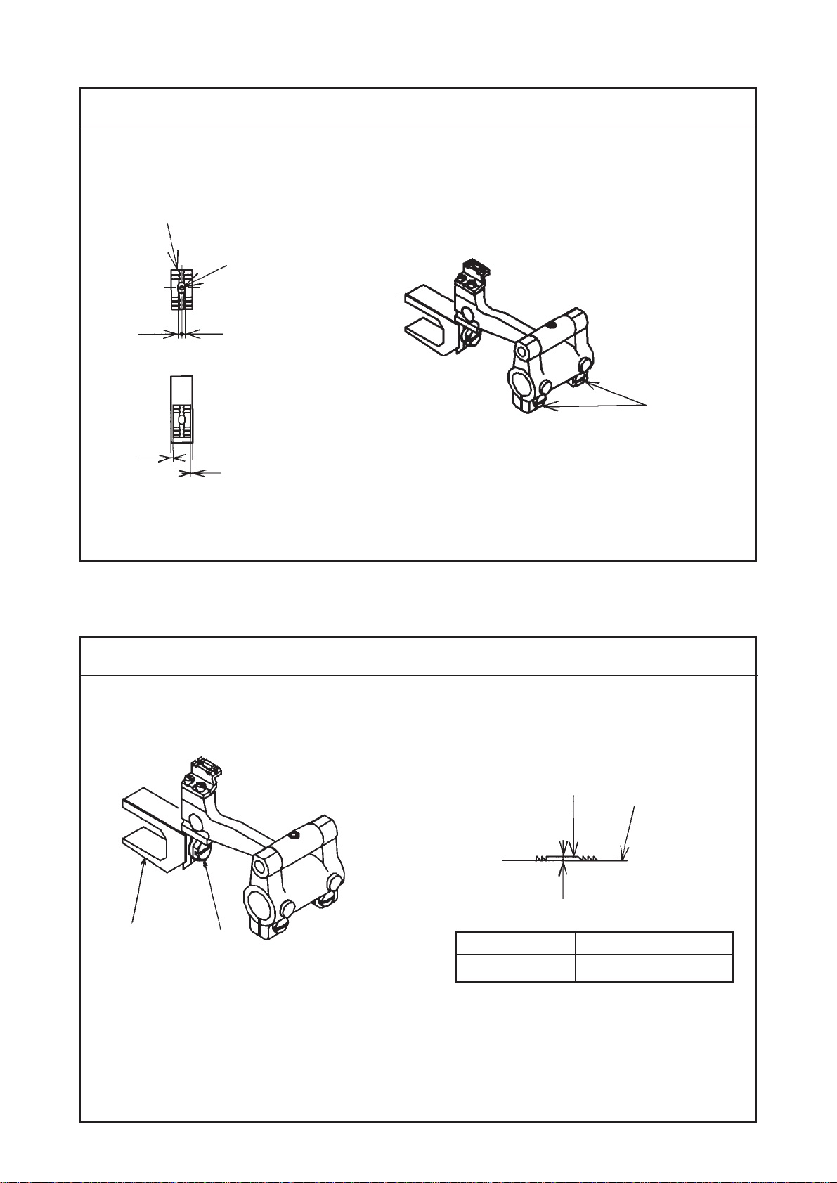
2) Needle-to-blade point of hook timing
1. Set the stitch dial to “0”.
2. Loosen two setcrews 3in the screw gear (large).
3. Turn the handwheel and when dimensions B and C are
approximately obtained, loosen setscrew A 4and setscrew B
8 in the hook shaft driving saddle. Then move the hook driving
shaft saddle to the right or left to adjust the cearance between
needle 5and blade point 6of the hook to dimension D. Then
securely tighten setscrew A 4and setscrew B 8.
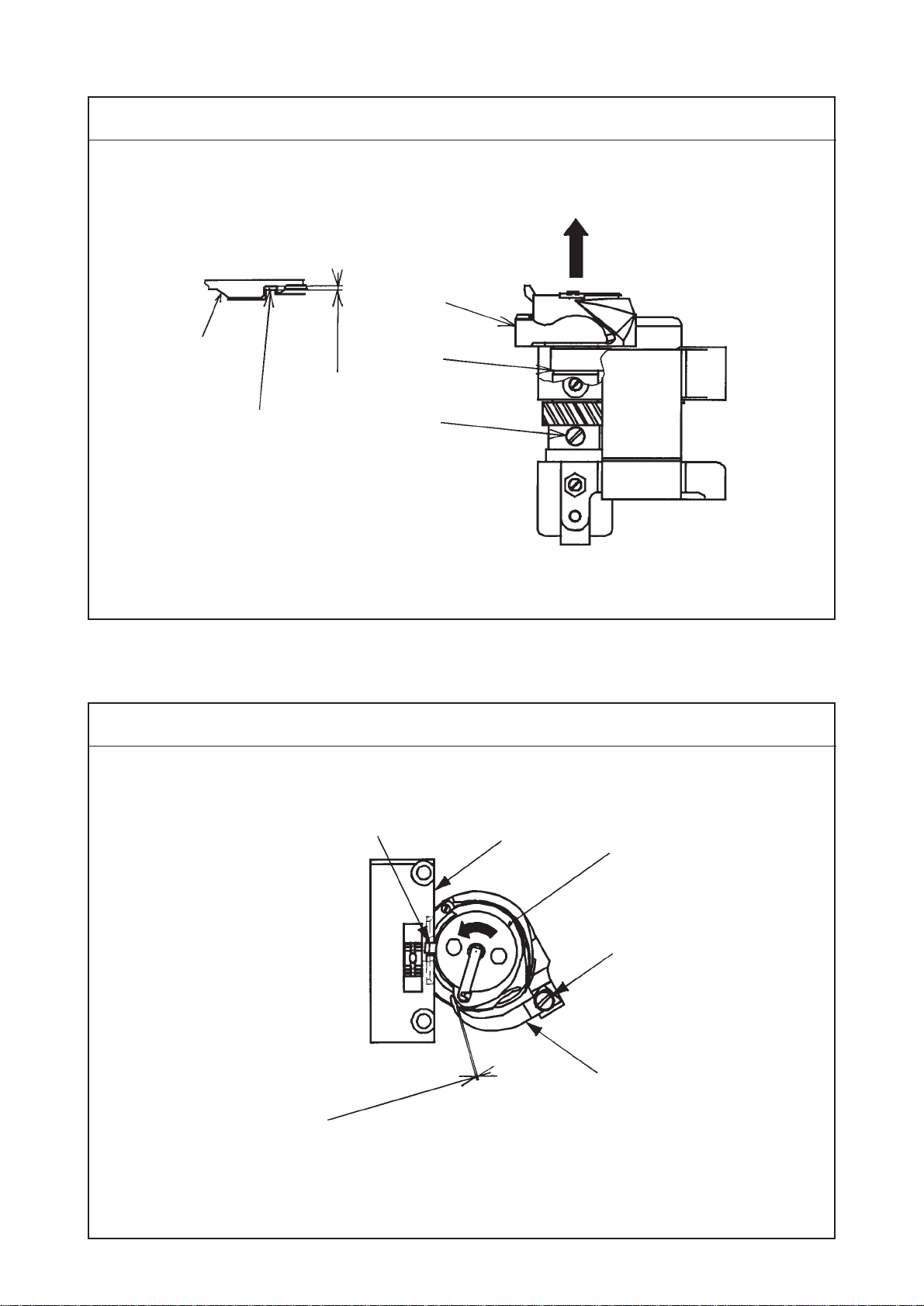
4. Turn the handwheel and move the screw gear (large) to the
right or left so that needle 5aligns with blade point 6of the
hook when needle bar 1is raised from the lowest dead point
of its stroke to dimension B. Then tighten two setscrews 3.
5. Turn the handwheel and loosen clamping screw 2in the needle
bar holder to adjust so that the distance from the top end of the
eyelet of needle 5to blade point 6of the hook becomes
dimension C when needle bar 1is raised from the lowest dead
point of its stroke to dimension B. Then tighten again the
clamping screw.
6. Set the stitch dial to the maximum and check that needle 5
does not come in contact with blade point 6of the hook.
3) Adjusting the needle guard of the hook
1. Bend needle guard 7and adjust so that the needle guard 7
comes in contact 0.1 to 0.2 mm with the needle.
(Caution) 1. After tightening the hook shaft screw gear,
check that the hook shaft has no thrust play.
2. Check that the hook shaft screw gear has
backlash.

– 10 –
(8) Lift of the presser foot
1) Hand lifter
1
2
9±0.3 mm
Top surface of
throat plate
Condition
• State that the hand lifter is raised
Standard Adjustment
2) Automatic presser foot lifter
16±0.5 mm
Top surface of
throat plate
1
2
3
4
0.5 to 1.5 mm
B
A

– 11 –
1) Hand lifter
1. Loosen clamping screw 1in the presser bar bracket to set the
hand lifter 2to the raised state.
2. Adjust the lifting amount to 9 ±0.3 mm. At this time, the
adjustment can be easily performed when inserting a thing of
9 mm thick between the top surface of the throat plate and the
bottom face of the presser foot.
3. Tighten clamping screw 1in the presser bar bracket. Move
the presser foot to the left or the right and tighten the screw in
the state that the presser foot does not interfere with the walking
foot.
Adjustment Procedures Results of Improper Adjustment
When the lifting amount is higher
than the specified value :
™The presser foot is held raised
from the top surface of the throat
plate even when the hand lifter
is returned to its home position.
When the lifting amount is lower
than the specified value :
™The presser foot is not sufficiently
raised and the working property
may be deteriorated.
2) Automatic presser foot lifter
1. Loosen cylinder nut 1and adjust the screwing amount of
cylinder connecting screw 2so that the height from the top
surface of the throat plate to the bottom surface of the presser
foot becomes 16±0.5 mm.
™Turn in the direction A/Lifting amount is increased.
™Turn in the direction B/Lifting amount is decreased.
After the adjustment, check that there is a clearance of 0.5 to
1.5 mm between automatic presser foot lifter lever A 3and
thread tension release plate 4when the presser foot is
lowered.
When the lifting amount is higher
than the specified value :
™The top end of the needle bar
interferes with the walking foot
and the walking foot may be
damaged when the presser foot
is raised.
When the lifting amount is lower
than the specified value :
™The presser foot is not sufficiently
raised and the working property
may be deteriorated.

– 12 –
Standard Adjustment
Standard Adjustment
(10) Feed cam timing
(9) Timing between the upper shaft and the lower shaft
1) Horizontal feed cam timing
1
2
3
4
1
2
3
To be level
Conditions
• Feed amount : 0 mm
• Needle bar at lowest dead point
Screw No. 1 Main shaft Conditions
• Feed amount : maximum
• Needle bat at lowest dead point

– 13 –
Adjustment Procedures Results of Improper Adjustment
1. Set the stitch dial to “0”.
2. Remove timing belt 3.
3. Turn the handwheel to bring the needle bar to the lowest dead
point of its stroke.
4. Turn screw No. 2 1so that it is level to top surface 2of the
machine bed.
5. Fit timing belt 3to lower sprocket 4.
(Caution) Theillustrationisasobserved from thehandwheel side.
™Pitch error at high or low speed
will be deteriorated.
™Thread tension will vary.
™Stitch tightness at normal and
reverse feed will vary.
™Stitches wil be poorly tensed.
™Feed timing and needle to hook
timing will vary.
1) Horizontal feed cam timing
1. Set the stitch dial to the maximum.
2. Loosen two setscrews 1in the horizontal feed eccentric cam.
3. Turn the handwheel to bring the needle bar to the lowest dead
point of its stroke.
4. Turn feed eccentric cam 2and adjust the timing so that the
feed dog no longer moves even when the reverse feed control
lever is moved.
5. Securely tighten two setscrews 1in the horizontal feed
eccentric cam.
(Standard) The setscrew No. 1 in the horizontal feed eccentric
cam faces almost right above at the lowest dead point of
the needle bar.
(Caution)
1. If the cam slips in the axial direction at the time of
adjustment, torque becomes heavy. So, be careful.
2. Adjust the horizontal feed rod so that it comes almost
in the center between the edge of horizontal feed cam
lid 3and that of horizontal feed eccentric cam.
3. After adjusting the horizontal feed timing, re-adjust the
vertical feed timing.

– 14 –
2) Top feed cam timing
™When DL device is not provided ™When DL device is provided
Standard Adjustment
13
4
5
Main shaft
Top feed cam rod
To align
Conditions
• Feed amount : 6 mm
• When needle and walking foot are lowered.
Top feed cam rod
2
Top feed cam rod Screw No.1
Screw No.1

– 15 –
Adjustment Procedures Results of Improper Adjustment
2) Top feed cam timing
1. Set the stitch dial to “6”.
2. Set the alternate vertical dial to "3".
3. Remove the window plate setscrew and remove the window
plate and the window plate packing.
4. Loosen two setscrews 1in the top feed cam.
5. Turn top feed cam 5to the position where three points of top
end 2of the needle eyelet, top surface 3of the throat plate
and walking foot 4(pressing face) are aligned with one another
on condition that the amount of alternate vertical movement of
both the walking foot and the presser foot is equal.
6. Securely tighten two setscrews 1in the top feed cam.
(Standard) Screw No. 2 of top feed cam 5faces just above
and screw No. 1 of top feed cam 5faces to the direction of
the arrow when needle tip 2and walking foot 4align with
top surface 3of the throat plate at the time of their going
up.
(Adjust the timing at the position where three points are
aligned with one another when top end 2of the needle
and walking foot 4are coming down.)
™Pitch error at high or low speed
will be deteriorated.

– 16 –
Standard Adjustment
(11) Feed motion
1) Amount of alternate vertical movement (position of the vertical adjusting arm)
1
2
2) Alternate momentum
12
3
A
B
Top surface of
feed dog
Top surface of
throat plate Top surface of
throiat plate
Conditions
• Feed amount : 0 mm
• Amount of alternate vertical movement : standard
1
4
3
73 to 74 mm
Operator’s
side
Edge of
machine arm
To align
with edge
73 to 74 mm

– 17 –
Adjustment Procedures Results of Improper Adjustment
1) Amount of alternate vertical movement
1. Remove the top cover.
2. Loosen setscrew 4in the vertical adjusting arm.
3. Adjust the position of vertical adjusting arm 1to 73 to 74 mm
from edge 2of the machine arm and assemble it so that it
aligns with the edge of vertical change base 3in the lateral
direction.
4. Securely tighten setscrew 4in the vertical adjusting arm.
5. Set the alternate vertical dial to the minimum and attach the
top cover.
6. Turn the alternate vertical dial and check to be sure that the
scale of dial and the amount of alternate vertical movement
are correct.
Increase the vertical stroke of the
walking foot in accordance with the
sewing products.
™Sewing sponge material or the
like
™Sewingmaterialwithoverlapped
sections
2) Alternate momentum
1. Set the stitch dial to “0”.
2. Turn the handwheel to make sure that the amount of alternate
vertical movement of walking foot 1and presser foot 2is
almost equal.
3. When the amount is not equal, loosen setscrew 3in the top
feed rear arm and adjust so that the amount should be equal.
Adjust the amount almost to A = B.
™When the amount of alternate vertical movement of the walking
foot is larger than that of the presser foot :
1) Loosen setscrew 3in the top feed rear arm in the state that
walking foot 1is raised a little, press walking foot 1to the
feed dog.
2) Re-tighten setscrew 3in the top feed rear arm and turn the
handwheel to make sure of the amount of alternate vertical
movement.
Adjust the vertical stroke of the
walking foot so that it is larger than
thatofthepresserfootin accordance
with the sewing products.
™Sewing sponge material or the
like
™Sewingmaterialwithoverlapped
sections
When the alternative vertical
strokes of the walking foot and
presser foot are considerably
different
™The stitch pitch is different from
the value set by the dial.
™Decreasethe number of revolution
of the motor a little since the feed
efficiency is decreased.

– 18 –
Standard Adjustment
(12) Needle sway (Adjusting the bottom feed amount)
12
3
20±0.5 mm
Horizontal feed shaft
Engraved marker line
Standard Adjustment
(13) Stitch length of normal/reverse feed
1
2
A
B
Feed adjusting base
Notch Feed adjusting rod
Conditions
• Feed amount : 6 mm

– 19 –
Adjustment Procedures Results of Improper Adjustment
™Needle breakage or stitch
skipping will result.
1. Loosen hinge screw nut 1in the horizontal feed rear arm.
2. Move horizontal feed connecting rod 2so that the distance
from the center of the horizontal feed shaft to that of the hinge
screw is 20 ±0.5 mm and tighten the nut 1.
3. Turn the handwheel to check the needle sway.
(Standard) 1. The engraved marker line on horizontal feed
rear arm 3aligns with the center of the hinge
screw.
2. When the distance is lengthened more than the
standard adjustment value, the bottom feed
amount is decreased.
(Caution) When you desire to change the bottom feed amount,
re-adjust the needle entry position since the needle entry
position changes.
Adjustment Procedures Results of Improper Adjustment
1. Set the stitch dial to “6”.
2. Loosen two setscrews 1in the feed adjusting eccentric pin.
3. Turn feed adjusting eccentric pin 2to adjust the stitch
™length.Direction A /reverse feed pitch is increased.
™Direction B /normal feed pitch is increased.
4. After the adjustment, securely tighten two setscrews 1in the
feed adjusting eccentric pin.
(Standard) When the direction of the notch of feed adjusting
eccentric pin 2is set to the right sideway as shown in the
illustration, the feed amounts of normal and reverse feeds
are nearly the same.
™Respective stitch lengths of
normal and reverse feeds do not
match.

– 20 –
Standard Adjustment
(14) Position of the reverse feed control lever
1
2
3
1±0.5 mm
3
Feed
regulator Reverse feed lever shaft
Standard Adjustment
(15) Safety clutch
1
2
A
B
4
1
* Standard of release pressure
3
13
2
24.5N•m 9.8N•m
5.9N•m
Other manuals for LU-1520N-7
1
Table of contents
Other JUKI Sewing Machine manuals

JUKI
JUKI LK-1910 User manual

JUKI
JUKI HZL-12Z User manual

JUKI
JUKI AMS-210EN Series User manual

JUKI
JUKI MO-655N User manual

JUKI
JUKI NA-35UT Guide

JUKI
JUKI HZL-T100 User manual

JUKI
JUKI MF-7000 Series Quick start guide

JUKI
JUKI MF-7900 Series User manual

JUKI
JUKI MO-1000 User manual

JUKI
JUKI LZH-1290 User manual

JUKI
JUKI SC-920 User manual

JUKI
JUKI TL-2000Qi User manual

JUKI
JUKI IT-100D User manual

JUKI
JUKI MO-2000QVP User manual

JUKI
JUKI AMS-210EN-SS1306 User manual

JUKI
JUKI AMS-210D User manual

JUKI
JUKI MO-634DEV User manual

JUKI
JUKI K-1E User manual

JUKI
JUKI LU-2810-7 Series User manual

JUKI
JUKI HZL-27Z User manual