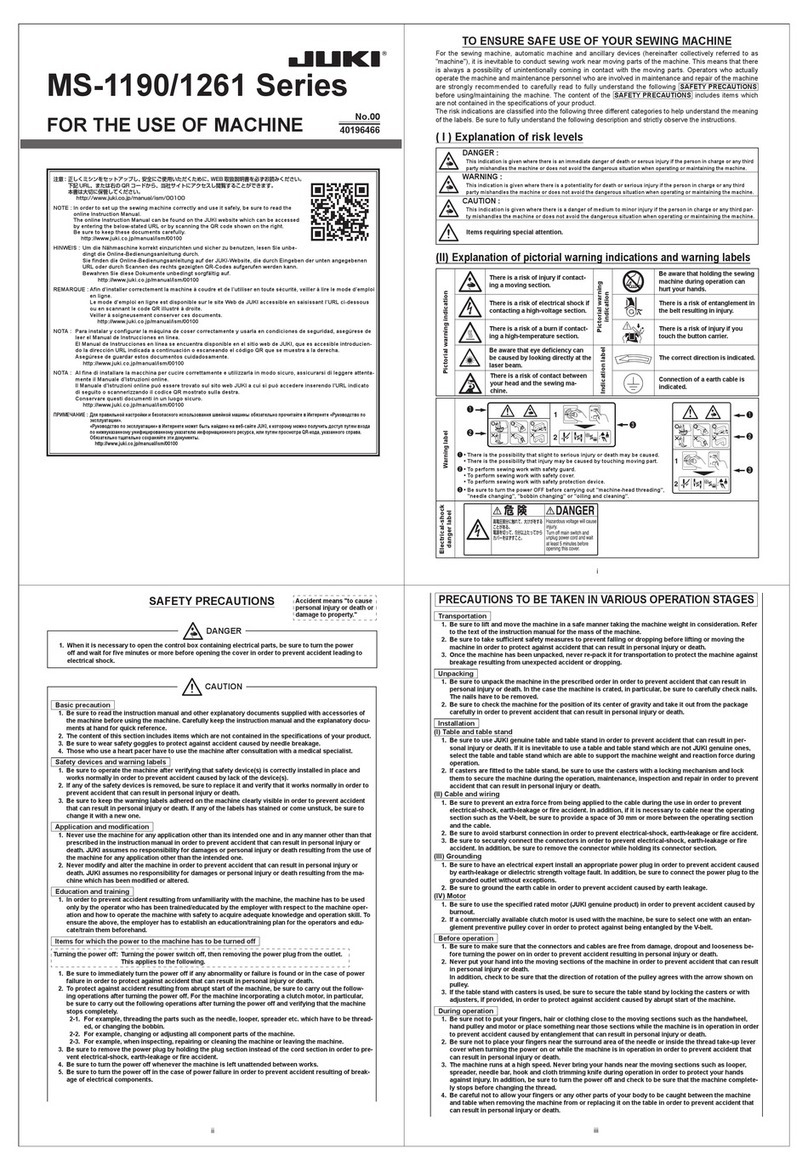
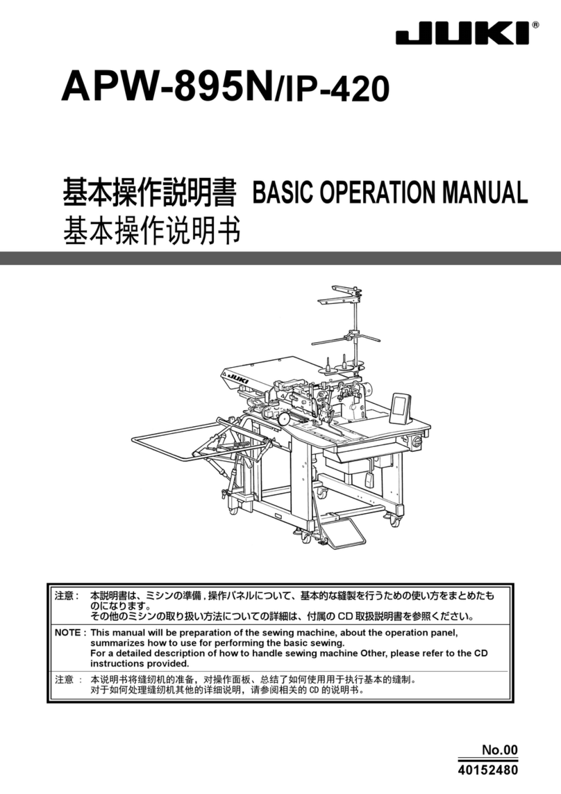
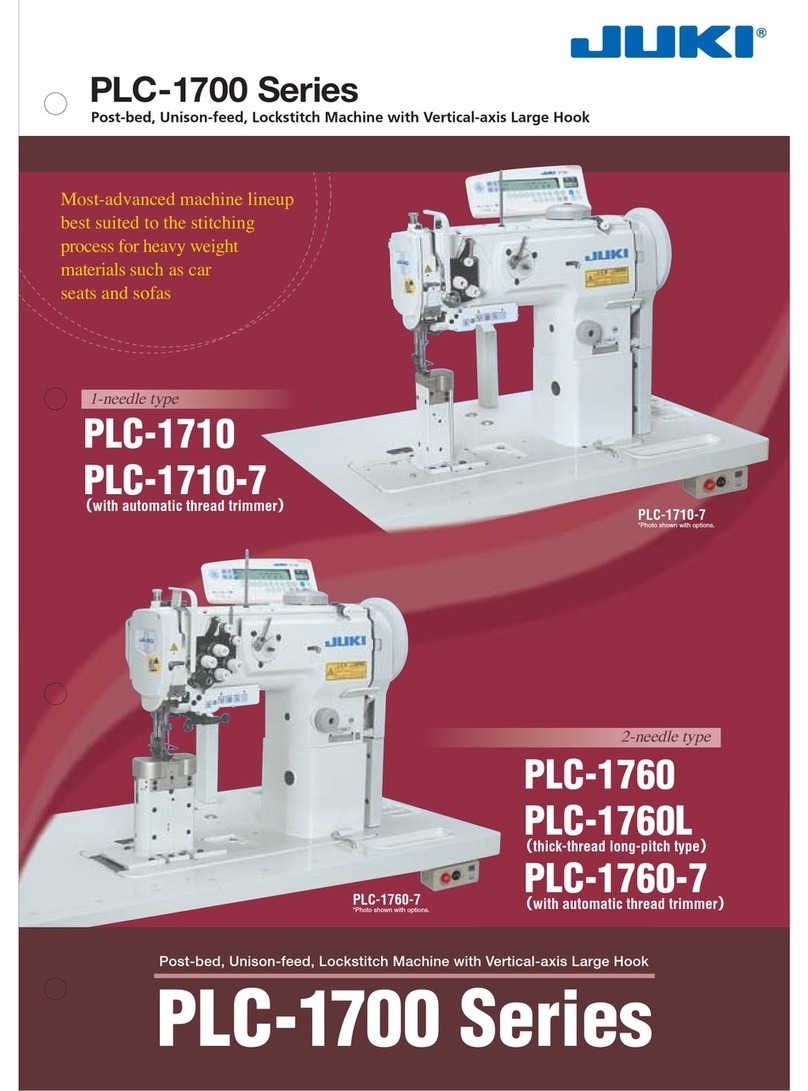
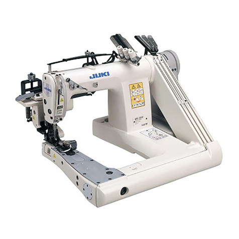
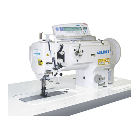
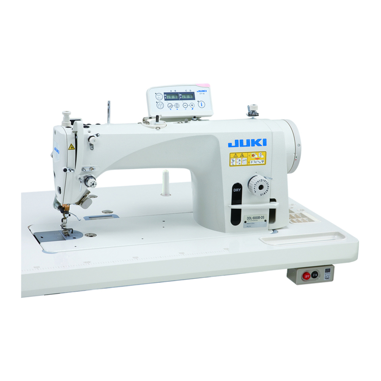
JUKI PLC-2710N-7 User manual

PLC-2710N-7,2760N,2760N-7,2760NL
INSTRUCTION MANUAL

ii
CONTENTS
1. Specications ................................................................................................................. 1
2. Threading the machine head......................................................................................... 3
3. Setting the pneumatic center guide (PLC-2760N,2760N-7,2760NL)........................... 5
3-1. Selection of the optional input function .............................................................. 5
3-2. Selection of the optional output function............................................................ 6
3-3. Setting the ancillary device (PLC-2760N,2760NL) .............................................. 7
3-4. Piping of the air (PLC-2760N,2760NL) ................................................................. 8
CAUTION
This Instruction Manual for the PLC-2710N-7,2760N,2760N-7,2760NL only describes their dif-
ferences from the standard models (PLC-2710-7,2760,2760-7,2760L).
For safety-related information, carefully read and fully understand "Safety precautions"
described in the Instruction Manual for the standard models before using your sewing ma-
chine.

– 1 –
1. Specications
No. Item Application
1 Model PLC-2760N PLC-2760NL
2 Model name Post-bed, 2-needle, unison-feed,
lockstitch machine with vertical-axis
large Hook
Post-bed, 2-needle, unison-feed,
lockstitch machine (for thick thread)
3 Application Medium- to heavy-weight materials, car
seat, furniture
Heavy-weight materials, car seat,
furniture
4 Sewing speed Max. 2,500 sti/min
(Refer to "6. SEWING SPEED TABLE"
in the Instruction Manual for the
standard model.)
Max. 2,000 sti/min
(Refer to "6. SEWING SPEED TABLE"
in the Instruction Manual for the
standard model.)
5 Needle GROZ-BECKERT 135 x 17 (Nm 100 to
Nm 180) (Standard : Nm 140)
GROZ-BECKERT 135 x 17
(Nm 140 to Nm 200)
(Standard : Nm 200)
6 Applicable thread size for
sewing #30 to #5 #8 to #0
7 Applicable thread size to
be cut
8 Stitch length Max. 12 mm (forward/reverse feed)
9 Stitch length dial 1-pitch dial
10 Presser foot lift Hand lifter : 10 mm
Knee lifter : 20 mm
11 Stitch length adjusting
mechanism
By dial
12 Reverse stitch adjusting
method
By lever
13 Thread take-up Link thread take-up
14 Needle bar stroke 40 mm
15 Amount of the alternate
vertical movement
1 mm to 9 mm (Alternate vertical dial adjustment type)
16 Hook Vertical-axis 2-fold hook (Latch type)
17 Feed mechanism Box feed
18 Top and bottom feed
actuation mechanism
Timing belt
19 Thread trimming method
20 Lubrication Automatic lubrication by oil tank (with oil gauge)
21 Lubricating oil JUKI New Defrix Oil No. 1 (equivalent to ISO standard VG7)
or JUKI MACHINE OIL No. 7
22 Bed size 643 mm × 178 mm
23 Space under the arm 347 mm × 298 mm
24 Hand wheel size V-belt eective diameter : ø76.0 mm
Outer diameter : ø140 mm
25 Motor/Control box M51N 750W / SC-922A
26 Machine head weight 79 kg
27 Noise - Equivalent continuous emission
sound pressure level (LpA) at the
workstation:
A-weighted value of 84.0 dB;
(Includes KpA = 2.5 dB); according to
ISO 10821- C.6.2 - ISO 11204 GR2
at 2,500 sti/min.
-Sound power level (LWA);
A-weighted value of 86.0 dB;
(Includes KWA = 2.5 dB); according to
ISO 10821- C.6.2 - ISO 3744 GR2 at
2,500 sti/min.
-Equivalent continuous emission
sound pressure level (LpA) at the
workstation:
A-weighted value of 88.0 dB;
(Includes KpA = 2.5 dB); according to
ISO 10821- C.6.2 - ISO 11204 GR2
at 2,000 sti/min.
-Sound power level (LWA);
A-weighted value of 93.5 dB;
(Includes KWA = 2.5 dB); according to
ISO 10821- C.6.2 - ISO 3744 GR2 at
2,000 sti/min.

– 2 –
No. Item Application
1 Model PLC-2710N-7 PLC-2760N-7
2 Model name Post-bed, 1-needle, unison-feed,
lockstitch machine with vertical-axis
large hook, with thread trimmer
Post-bed, 2-needle, unison-feed,
lockstitch machine with vertical-axis
large hook, with thread trimmer
3 Application Medium- to heavy-weight materials, car seat, furniture
4 Sewing speed Max. 2,500 sti/min
(Refer to "6. SEWING SPEED TABLE"
in the Instruction Manual for the standard model.) *1
5 Needle GROZ-BECKERT 135 x 17 (Nm 100 to Nm 180) (Standard : Nm 140)
6 Applicable thread size for
sewing
#30 to #5
7 Applicable thread size to
be cut
#30 to #5
8 Stitch length Max. 12 mm (forward/reverse feed)
9 Stitch length dial 2-pitch dial
10 Presser foot lift Hand lifter : 10 mm
Automatic presser foot lifter : 20 mm
11 Stitch length adjusting
mechanism
By dial
12 Reverse stitch adjusting
method
Air cylinder type (with touch-back switch)
13 Thread take-up Link thread take-up
14 Needle bar stroke 40 mm
15 Amount of the alternate
vertical movement
1 mm to 9 mm (Alternate vertical dial adjustment type)
16 Hook Vertical-axis 2-fold hook (Latch type)
17 Feed mechanism Box feed
18 Top and bottom feed
actuation mechanism
Timing belt
19 Thread trimming method Cam-driven scissors type
20 Lubrication Automatic lubrication by oil tank (with oil gauge)
21 Lubricating oil JUKI New Defrix Oil No. 1 (equivalent to ISO standard VG7)
or JUKI MACHINE OIL No. 7
22 Bed size 643 mm × 178 mm
23 Space under the arm 347 mm × 298 mm
24 Hand wheel size Outer diameter : ø123 mm
25 Motor/Control box SC-922B
26 Machine head weight 81 kg 84 kg
27 Rated power consumption 193VA
28 Noise -Equivalent continuous emission
sound pressure level (LpA) at the
workstation:
A-weighted value of 79.5 dB;
(Includes KpA = 2.5 dB); according to
ISO 10821- C.6.2 - ISO 11204 GR2
at 2,500 sti/min.
-Equivalent continuous emission
sound pressure level (LpA) at the
workstation:
A-weighted value of 84.0 dB;
(Includes KpA = 2.5 dB); according to
ISO 10821- C.6.2 - ISO 11204 GR2
at 2,500 sti/min.
-Sound power level (LWA);
A-weighted value of 86.0 dB;
(Includes KWA = 2.5 dB); according to
ISO 10821- C.6.2 - ISO 3744 GR2 at
2,500 sti/min.
*1 The speed setting according to the amount of the alternating vertical movement of the walking
foot and presser foot is automatically carried out.

– 3 –
[PLC-2710N-7]
Thread the machine head following the
order as illustrated in the gure.
WARNING :
To protect against possible personal injury due to abrupt start of the machine, be sure to start the
following work after turning the power o and ascertaining that the motor is at rest.
* Pass thread through the right
side of thread guide .
2. Threading the machine head
❼
❹
❺
❻
❾
❸
❺
❼
❻
❶
❷
❹
❽
❽

– 4 –
❶❶
❾
❸
❺
❼
❷
❽
❹
❻
❻
❺
❹
❸
❻
❺
❹
❸
❼
[PLC-2760N, 2760N-7, 2760NL]
Thread the machine head following the
order as illustrated in the gure.
WARNING :
To protect against possible personal injury due to abrupt start of the machine, be sure to start the
following work after turning the power o and ascertaining that the motor is at rest.
Right-hand
needle thread
Left-hand
needle thread
PLC-2760N-7 PLC-2760N, 2760NL

– 5 –
❻
❺❹❸
❶
❷ ❼
ⒷⒶ
0i 6 on P
1 2 TPo_
2L 9
0i 6 UGCd
0i 6 2L 9
2H 9
0i 7 on P
nEd
_ni _
TPo_
in
TPo_
3. Setting the pneumatic center guide (PLC-2760N,2760N-7,2760NL)
3-1. Selection of the optional input function
1. While holding down switch ❼, turn the power ON. (The display items that have been changed
in the previous operation will be displayed.)
* If the screen display does not change, start over the operation again from the beginning.
2. Press switch ❹to advance the setting number to select
the function No. 12. If you want to return the setting number,
press switch ❸to return it.
(Caution) When you advance (return) the setting number,
the previous (or next) content is confirmed. It is
necessary, therefore, to be very careful when you have
changed the content (i.e., touched the switch).
3. Select the item of "in" with keys ❺and ❻.
4. Select i06 with key ❹.
5. Select the "CGUd" center guide switch input function with keys
❺and ❻.
6. Determine the "CGUd" center guide switch input function with
key ❹.
7. Set the ACTIVE of the signal with keys ❺and ❻.
Set the display to "L" if the operation is carried out when the
signal is "Low". Set the display to "H" if the operation is carried
out when the signal is "High".
8. Determine the aforementioned function with key ❹.
9. Finish the optional input with key ❹.
10.
Select the item of "End" with keys ❺and ❻to return to the function
setting mode.
Lighting alternately

– 6 –
3-2. Selection of the optional output function
1 2 TPo_
3L 3
3H 3
nEd
TUo_
TPo_
on P
1o5
UGCd
1o5
3L 3
1o5
on P
1o6
TUo_
TPo_
*1 Item to be selected diers with the model.
o13:PLC-2760N,2760NL
o15:PLC-2760N-7
1. Select the function No. 12 with the operating procedure of the
optional input setting procedures 1 and 2.
2. Select the item of "oUT" with keys ❺and ❻.
3. Select o13/o15 with key ❹. *1
4. Select the "CGUd" center guide switch input function with keys
❺and ❻.
5. Determine the "CGUd" center guide switch input function with
key ❹.
6. Set the ACTIVE of the signal with keys ❺and ❻.
Set the display to "L" if the operation is carried out when the
signal is "Low". Set the display to "H" if the operation is carried
out when the signal is "High".
7. Determine the aforementioned function with key ❹.
8. Finish the optional output with key ❹.
9.
Select the item of "End" with keys ❺and ❻to return to the function
setting mode.
Lighting alternately

– 7 –
❻
❺❹❸
❶
❷ ❼
ⒷⒶ
3-3. Setting the ancillary device (PLC-2760N,2760NL)
41 1 nUF _
nE_ d
nUF _
1TU _
2TU _
*** *
1U 0
*** *
**
U*
0GC 1
0
0
0
G
G
G
C
C
C
2
3
4
1. While holding down switch ❼, turn the power ON.
If you keep the switch held pressed for three seconds or more, the buzzer will sound to allow you to
set the functions that are available under the Service mode.
2. Select the function No.141 with keys ❸and ❹.
3. Select the items of "_End", "UT1_", and "UT2_" with keys ❺and ❻.
4. If you have selected the UT1 or UT2, "U1 0" or "U2 0" will be displayed
on display unit Ⓐ. Then, specify the ancillary device setting item num-
ber with key ❸and ❹.
5. Select the parameter you want to set from the following with keys ❺
and ❻and input it.
PLC center guide
(Interlocked with the
BT/DL/Initialization of
the FL)
PLC center guide
(Interlocked with the
BT/DL/FL)
PLC center guide
(Interlocked with the
BT)
PLC center guide
(Interlocked with the
BT/FL)

– 8 –
3-4. Piping of the air (PLC-2760N,2760NL)
CN151
CN152 CN154
CN155
CN153
Center guide
(With no wire mark)
AK
(Wire mark ⑩)
BT
(Wire mark ⑧)
DL
(Wire mark ⑥)
Plug
(PX950013000)
Connect the air hose coming from the machine head to the position shown above while matching the
number of the air hose and the number of the port.
Insert the plug into the half union of the CN154.
This manual suits for next models
3
Table of contents
Other JUKI Sewing Machine manuals

JUKI
JUKI MO-103N User manual

JUKI
JUKI LBH-1790 Series User manual

JUKI
JUKI Union Special 36200 CLASS Series Setup guide

JUKI
JUKI LBH-772NV-1 User manual

JUKI
JUKI LU-1560N User manual

JUKI
JUKI LK1903B/BSS302 User manual

JUKI
JUKI AMS-21 OD User manual

JUKI
JUKI LK-1900BN User manual

JUKI
JUKI HZL-G220 User manual

JUKI
JUKI MH-380 Owner's manual