JUKI SC-921 Manual

– 1-1 –
SUPPLEMENTARY SETUP INSTRUCTIONS
ERGÄNZENDE EINRICHTUNGSANLEITUNG
CONSIGNES D’INSTALLATION SUPPLÉMENTAIRES
INSTRUCCIONES SUPLEMENTARIAS PARA LA INSTALACIÓN
ISTRUZIONI SUPPLEMENTARI DI INSTALLAZIONE
安装设置补充说明书
TAMAMLAYICI KURULUM TALIMATLARI
ДОПОЛНИТЕЛЬНЫЕ УСТАНОВОЧНЫЕ ИНСТРУКЦИИ
SC-921
No.02
40105997
1) 窓板止めねじを窓板より取り外します。
1) Remove side plate setscrews from the side plate.
1) Die Befestigungsschrauben von der Seitenplatte entfernen.
1) Oterlesvisdexationdeplaquelatéraledelaplaquelatérale.
1) Retiredelaplacalaterallostornillosdejaciónde la placa lateral.
Installing the control panel /
Installieren der steueratafel / Installation du panneau de commande /
Modo de instalar el panel de control /
Installazione del pannello di comando / 控制盘的安装 /
Kontrolpanelininkurulmasi/Установка панели управления
WARNING :
Topreventpersonalinjurycausedbyabruptstartofthesewingmachine,carryoutthework
after turning OFF the power switch and ascertaining that the motor has completely stopped.
WARNUNG :
Schalten Sie vor Beginn der Arbeit die Stromversorgung aus, um durch plötzliches Anlaufen
der Nahmaschineverursachte Unfälle zu verhüten.
AVERTISSEMENT :
Pour ne pas risquer des blessures causées par une brusque mise en marche de la machine,
toujours placer l'interrupteur d'alimentation sur arrêt et s'assurer que le moteur est complè-
tement arrêté avant d'effectuer cette opération.
ADVERTENCIA :
Desconecte la corriente eléctrica y asegúrese que el motor se haya detenido completamente
antes de comenzar el trabajo para evitar accidentes causados por un arranque brusco de la
máquina de coser.
AVVERTIMENTO :
Prima di effettuare le seguenti operazioni assicurarsi di spegnere l’interruttore dell’alimenta-
zionealnedievitareincidenticausatidall’avvioimprovvisodellamacchinapercucire.
警告 :
为了防止突然起动造成人身事故,请关掉电源,确认马达确实停止转动后再进行操作。
UYARI :
Dikişmakinesininanidençalışarakyaralanmalarasebepvermemesiiçin,güçşalteriniKAPA-
LIkonumagetiripmotoruntamamendurduğundaneminolduktansonraçalışmayabaşlayın.
ПРЕДУПРЕЖДЕНИЕ :
Чтобы предотвратить травмы, вызванные внезапным запуском швейной машины, производите действия
после того, как отключите выключатель электропитания и убедитесь, электромотор полностью остановился.

– 1-2 –
2) コントロールパネルを、パネル付属のねじ・平座金・
およびゴム座を使用して頭部に取り付けます。
2) Install control panel on the machine head using screws ,
atwashersand rubber seat supplied with the control
panel as the accessories.
(Caution) 1. DDL-9000B (Not provided with AK) is given as an
example of installing procedure.
2. Screw to install the panel changes according to
the machine head used. Refer to Table 1 (p.1-3)
andconrmthekindofscrew.
2) Die Steuertafel mit den im Lieferumfang enthaltenen Schrauben , den Unterlegscheiben und dem
Gummisitz installieren.
(Vorsicht) 1. Das Modell DDL-9000B(AK nicht vorhanden) dient als Beispiel für das Installationsverfahren.
2.DieBefestigungsschraubenderTafelhängenvomverwendetenMaschinenkopfab.DieSchrau-
benart ist aus Tabelle 1 (S.1-4) ersichtlich.
2) Poser le panneau de commande sur la tête de la machine à l'aide des vis , des rondelles plates et du
siège en caoutchouc fournis comme accessoires avec le panneau de commande.
(Attention) 1. La DDL-9000B (Non disponible sur l’AK) est donnée comme un exemple de la procédure d'instal-
lation.
2. La vis de montage du panneau diffère selon la tête de machine utilisée. Voir le type de vis dans le
tableau 1 (p.1-4).
2) Instale el panel de control enelcabezaldelamáquinautilizandolostornillos, arandelas planas y
asiento de goma quesesuministranconelpaneldecontrolcomoaccesorios.
(Precaución) 1. Se utiliza el DDL-9000B(Sin AK) como ejemplo del procedimiento de instalación.
2. El tornillo para instalar el panel varía de acuerdo con el cabezal de máquina que se utilice. Con-
sulte la Tabla 1 (p.1-5)paraconrmareltipodetornillo.
2) Installare il pannello di comando sulla testa della macchina usando le viti , le rondelle piane e il tampo-
ne di gomma in dotazione con il pannello di comando.
(Attenzione) 1. La DDL-9000B(Non dotata del AK) è indicata come un esempio di procedura di installazione.
2. La vite per installare il pannello varia secondo la testa della macchina utilizzata. Consultare la
tabella 1 (p.1-5) e controllare il genere di vite.
2)请使用控制盘附属螺丝、平垫片以及橡胶座把控制盘安装到机头上。
( 注意 ) 1. 安装方法是以 DDL-9000B( 没有安装 AK) 为例说明。
2. 机头不同控制盘安装螺丝也不同。请参照表 1 (p.1-6),确认螺丝的种类。
2) Kontrolpaneliylebirlikteaksesuarolarakteminedilenvidaları,düzpullarıvelastikcontayıkullanarak,
kontrol panelini makinekafasınamonteedin.
(DİKKAT) 1.MontajprosedürüneörnekolarakDDL-9000B(AKilebirlikteteminedilmez)verilmiştir.
2.Panelinmontajındakullanılanvida,kullanılanmakinekafasınagöredeğişir.Tablo1(S.1-6)’i incele-
yerekvidatipinidoğrulayın.
2) Установитепанельуправлениянашпиндельнойголовке,используявинты,плоскиешайбыирезиновое
уплотнение,которыепоставляютсяспанельюуправлениявкачествепринадлежностей.
(Предocтережение) 1. DDL-9000B (Поставляется без AK) приводится в качестве примера процедуры установки.
2. Установочные винты для установки панели меняются в зависимости от используемой шпин-
дельной головки. Справляйтесь в Таблице 1 (c.1-7) и уточняйте виды винтов.
1) Rimuoverelevitidissaggiodellapiastralateraledalla piastra laterale.
1)从窗板上卸下窗板固定螺丝。
1) Yanplakadakitespitvidalarınıçıkarın.
1) Открутитевинты,удерживающиебоковуюпластину.

– 1-3 –
< The relation between the respective machine heads and the positions of installing hole of the
bracketareasdescribedinthetable.>
取付穴 ねじ
DDL-9000B -AK 付きM5 × 14 窓板ねじ
AK なしM5 × 12
LH-3500A -M5 × 14 窓板ねじ
DLN-9010 -3/16-28L=12 パネル付属ねじ
DDL-8700 系 -3/16-28L=12 パネル付属ねじ
DDL-5500 系※1 -3/16-28L=12 パネル付属ねじ
LZ-2280 系※1 -11/64-40L=7.8 頭部付属ねじ
表1
Table 1
Installing hole
Screw
DDL-9000B -
(Provided with AK)
M5 × 14 Side plate setscrew
(Not provided with AK)
M5 × 12
LH-3500A -M5 × 14 Side plate setscrew
DLN-9010 -3/16-28 L=12 Screw supplied with panel as
accessories
DDL-8700 series -3/16-28 L=12 Screw supplied with panel as
accessories
DDL-5500 series *1 -3/16-28 L=12 Screw supplied with panel as
accessories
LZ-2280 series *1 -11/64-40 L=7.8 Screws supplied with machine
head
※1
DDL-5556、LZ-228* は、パネル取り付け用補助ブラケットを頭部に
付属しています。取り付けにあたっては、頭部側の取扱説明書を確認の上、
セットアップ願います
*1 For the DDL-5556 and LZ-228*,
the machine head is supplied
withanauxiliarybracketfor
mounting the control panel as
an accessory. Be sure to install
the bracket while referring to
the instruction manual for the
machine head.
(Caution) 1. Screws to be used for installing the panel differ with the machine head, i.e., screws supplied with
the panel as accessories and the side plate setscrews. Select appropriate screws/setscrews refer-
ring to Table 1.
2. If the screw type is not correct, the tapped hole can be collapsed.
3. If you want to install the panel on the DDL-8700, be aware that the method to install it on the ma-
chine head differs depending on whether or not the machine head is provided with the AK device.
Machine head with the AK device :
InstallthepanelontheheadbracketsuppliedwiththeAK.(Theauxiliarybracketshouldbe
xedwiththesideplatesetscrews.)
Machine head without the AK device :
Remove the side plate setscrews and install the panel on the side plate using the screws sup-
plied with panel as accessories.
4. If you want to use the panel with the machine head for heavy-weight materials, install it referring to
the "Supplementary Instructions" for the machine head.

– 1-4 –
<DieBeziehungzwischendemjeweiligenMaschinenkopfunddenMontageloch-Positionendes
HaltersistausderTabelleersichtlich.>
<Letableausuivantindiquelespositionsdesoricesdemontagedelaplatinedexationàutili-
serpourlesdifférentestêtesdemachine.>
Tabelle 1
Montageloch
Schraube
DDL-9000B -
(AK vorhanden)
M5 × 14 Seitenplatten-Befestigungsschraube
(AK nicht vorhanden)
M5 × 12
LH-3500A - M5 × 14 Seitenplatten-Befestigungsschraube
DLN-9010 -3/16-28 L=12 Mit der Tafel gelieferte Schrauben
Serie DDL-8700 -3/16-28 L=12 Mit der Tafel gelieferte Schrauben
Serie DDL-5500 *1 -3/16-28 L=12 Mit der Tafel gelieferte Schrauben
Serie LZ-2280 *1 -11/64-40 L=7,8 Mit dem Maschinenkopf gelieferte
Schrauben
Oricede
montage Vis
DDL-9000B -
(Disponible sur l’AK)
M5 × 14 Visdexationdeplaquelatérale
(Non disponible sur l’AK)
M5 × 12
LH-3500A - M5 × 14 Visdexationdeplaquelatérale
DLN-9010 -3/16-28 L=12 Vis fournie comme accessoire avec
le panneau
Modèles DDL-8700 -3/16-28 L=12 Vis fournie comme accessoire avec
le panneau
Modèles DDL-5500 *1 -3/16-28 L=12 Vis fournie comme accessoire avec
le panneau
Modèles LZ-2280 *1 -11/64-40 L=7,8 Vis fournies avec la tête de
machine
Tableau 1
*1 Bei den Modellen DDL-
5556 und LZ-228* ist
der Maschinenkopf mit
einem Zusatzhalter für die
Montage der Steuertafel
als Zubehör ausgestattet.
Montieren Sie den Halter
gemäß den Angaben in
der Bedienungsanleitung
des Maschinenkopfes.
(Vorsicht)1.DiefürdieMontagederTafelzuverwendendenSchraubensindjenachdemMaschinenkopfun-
terschiedlich, d. h. mit der Tafel gelieferte Schrauben und Seitenplatten-Befestigungsschrauben.
Wählen Sie die geeigneten Schrauben/Befestigungsschrauben gemäß Tabelle 1 aus.
2.FallsderSchraubentypnichtkorrektist,kanndieGewindebohrungzerstörtwerden.
3. Wenn Sie die Tafel am Modell DDL-8700 montieren wollen, beachten Sie, dass die Montagemethode
amMaschinenkopfunterschiedlichist,jenachdem,obderMaschinenkopfmitderAK-Vorrichtung
ausgestattet ist oder nicht.
MaschinenkopfmitAK-Vorrichtung:
DieTafelandemmitderAK-VorrichtunggeliefertenMaschinenkopfhalterinstallieren.(DerZu-
satzhalter ist mit den Seitenplatten-Befestigungsschrauben anzubringen.)
MaschinenkopfohneAK-Vorrichtung:
Die Seitenplatten-Befestigungsschrauben entfernen, und die Tafel mit den mitgelieferten Schrau-
ben an der Seitenplatte installieren.
4.WennSiedieTafelmiteinemMaschinenkopffürschwereStoffeverwendenwollen,installierenSie
diesegemäßder"Zusatz-Bedienungsanleitung"fürdenMaschinenkopf.
*1 Pour les modèles DDL-
5556 et LZ-228*, la tête
demachineestdotéed’un
supportauxiliairepour
le montage du panneau
de commande comme
accessoire. Pour installer
le support, vous devez
vous reporter au mode
d’emploi de la tête de
machine.
(Attention)1.Lesvisàutiliserpourinstallerlepanneau,c’est-à-direlesvisfourniesaveclepanneaucommeac-
cessoiresetlesvisdexationdeplaquelatérale,varientsuivantlatêtedemachine.Sélectionner
lesvisetvisdexationappropriéesenvousreportantauTableau1.
2.Silavisn’estpasdubontype,lesletsdutroutaraudérisquentdefoirer.
3.Sil’oninstallelepanneausurlaDDL-8700,nepasoublierquelafaçondel’installersurlatêtede
machine varie selon que la tête de machine est dotée ou non du dispositif AK.
Tête de machine dotée du dispositif AK :
Installerlepanneausurlesupportdetêtefourniavecl’AK.(Lesupportauxiliairedoitêtrexéà
l’aidedesvisdexationdeplaquelatérale.)
Tête de machine sans dispositif AK :
Retirerlesvisdexationdeplaquelatéraleetinstallerlepanneausurlaplaquelatéraleàl’aide
des vis fournies avec le panneau comme accessoires.
4. Pour utiliser le panneau avec la tête de machine pour matériaux très lourds, l’installer en se repor-
tant aux « Instructions supplémentaires » de la tête de machine.

– 1-5 –
< La relazione tra le rispettive teste della macchina e le posizioni del foro di montaggio del su-
pportoèdescrittanellatabella>
Foro di
montaggio Vite
DDL-9000B - (Dotata del AK) M5 × 14 Vitedissaggiodellapiastralaterale
(Non dotata del AK) M5 × 12
LH-3500A - M5 × 14 Vitedissaggiodellapiastralaterale
DLN-9010 - 3/16-28 L=12 Vite in dotazione con il pannello
Serie DDL-8700 - 3/16-28 L=12 Vite in dotazione con il pannello
Serie DDL-5500 *1 - 3/16-28 L=12 Vite in dotazione con il pannello
Serie LZ-2280 *1 - 11/64-40 L=7,8 Viti in dotazione con la testa della
macchina
Tabella 1
Tabla 1
< La relación entre las posiciones de los agujeros de insta-
lación de la ménsula y respectivos cabezales de máquina
escomoseindicaenlasiguientetabla.>
Agujerode
instalación Tornillo
DDL-9000B - (Con AK) M5 × 14 Tornillodejacióndeplaca
lateral
(Sin AK) M5 × 12
LH-3500A - M5 × 14 Tornillodejacióndeplaca
lateral
DLN-9010 - 3/16-28 L=12 Tornilloquesesuministra
como accesorio con el panel
Serie DDL-
8700 - 3/16-28 L=12 Tornilloquesesuministra
como accesorio con el panel
Serie DDL-
5500 *1 - 3/16-28 L=12 Tornilloquesesuministra
como accesorio con el panel
Serie LZ-2280
*1 - 11/64-40 L=7,8 Tornillos suministradovs con
elcabezaldemáquina
*1 Para DDL-5556 y LZ-228*, el cabezal de
lamáquinasesuministraconunaménsula
auxiliar,comoaccesorio,paramontajedel
panel de control. Asegúrese de instalar
laménsulaconsultandoelmanualde
instruccionesdelcabezaldelamáquina.
(Precaución)1.Lostornillosautilizarparainstalarelpaneldierensegúnelcabezaldemáquina,esdecir,los
tornillos suministrados con el panel como accesorios y los tornillos de sujeción de la placa lat-
eral.Porlotanto,seleccionelostornillos/tornillosdejaciónconsultandolaTabla1.
2. Si el tipo de tornillo no es el correcto, el agujero para roscar se puede dañar.
3. Si desea instalar el panel en DDL-8700, tenga en cuenta que el método para instalarlo en el
cabezaldemáquinadieredependiendodesielcabezaldemáquinaestáequipadoonoconel
dispositivo AK.
Cabezal de máquina con dispositivo AK :
Instale el panel sobre la ménsula de cabezal que se suministra con el dispositivo AK. (La
ménsulaauxiliardebejarseconlostornillosdejacióndelaplacalateral.)
Cabezal de máquina sin dispositivo AK :
Retirelostornillosdejacióndelaplacalateraleinstaleelpanelsobrelaplacalateralutili-
zando los tornillos suministrados con el panel como accesorios.
4. Si desea utilizar el panel con el cabezal de máquina para materiales pesados, instálelo con-
sultando las “Instrucciones suplementarias” para el cabezal de máquina.
*1 Per la DDL-5556
e LZ-228*, una
staffa ausiliaria per
il montaggio del
pannello di comando
è in dotazione con la
testa della macchina.
Assicurarsi di
installare la staffa
facendo riferimento al
manuale d'istruzioni
per la testa della
macchina.
(
Attenzione) 1. Le viti da utilizzare per l'installazione del pannello variano a seconda della testa della macchina,
cioè,levitiindotazioneconilpannelloelevitidissaggiodellapiastralaterale.Selezionarele
viti/vitidissaggioappropriatefacendoriferimentoallaTabella1.
2.Seiltipodivitenonècorretto,ilforolettatopuòessererovinato.
3. Se si desidera installare il pannello sulla DDL-8700, tenere presente che il metodo per installarlo
sulla testa della macchina si differenzia a seconda se la testa della macchina è dotata del dispos-
itivo AK.
Testa della macchina con il dispositivo AK :
Installare il pannello sulla staffa della testa in dotazione con il AK. (La staffa ausiliaria deve
esseressataconlevitidissaggiodellapiastralaterale.)
Testa della macchina senza il dispositivo AK :
Rimuoverelevitidissaggiodellapiastralateraleeinstallareilpannellosullapiastralaterale
tramite le viti in dotazione con con il pannello.
4. Se si desidera utilizzare il pannello con la testa della macchina per materiali pesanti, installarlo
facendo riferimento alle "Istruzioni supplementari" per la testa della macchina.

– 1-6 –
<机头部和支架安装孔位置>
<Farklımakinekafalarıylabraketmontajdeliğininkonumlarıarasındakiilişkitablodaverilmiştir.>
表1
Tablo 1
安装孔 螺丝
DDL-9000B - 安装 AKM5×14 窗板螺丝
没有安装 AKM5×12
LH-3500A - M5×14 窗板螺丝
DLN-9010 - 3/16-28 L=12 操作盘附属螺丝
DDL-8700 系 - 3/16-28 L=12 操作盘附属螺丝
DDL-5500 系 ※1 - 3/16-28 L=12 操作盘附属螺丝
LZ-2280 系 ※1 - 11/64-40L=7.8 机头附属螺丝
( 注意 ) 1. 有的机头的附属螺丝、窗板螺丝是共用的。请确认了一览表之后再选择螺丝。
2. 螺丝的规格不正确的话,有弄坏螺丝孔的危险。
3. 在 DDL-8700 上安装时,有带 AK 和不带 AK 的不同安装方法。
带 AK :请安装到 AK 附属的机头支架上。( 辅助支架请用窗板螺丝进行固定 )
不带 AK :请卸下窗板固定螺丝,换成附属螺丝,安装到窗板上。
4. 使用于厚料规格的机头时,请按照机头的「补充说明书」进行安装。
※1 DDL-5556、LZ-228※ 的操作盘是用
安装辅助支架附属在机头上的。安装
时,请确认了机头的使用说明书之后
再进行安装。
Montaj
deliği Vida
DDL-9000B - (Disponible sur l’AK) M5 × 14 Yanplakatespitvidası
(Non disponible sur l’AK) M5 × 12
LH-3500A - M5 × 14 Yanplakatespitvidası
DLN-9010 - 3/16-28 L=12 Panelle birlikte aksesuar
olarak temin edilen vida
DDL-8700 serisi - 3/16-28 L=12 Panelle birlikte aksesuar
olarak temin edilen vida
DDL-5500 serisi *1 - 3/16-28 L=12 Panelle birlikte aksesuar
olarak temin edilen vida
LZ-2280 serisi *1 - 11/64-40 L=7,8 Makinekafasıylabirlikte
temin edilen vidalar
*1 DDL-5556 ve LZ-228*
modellerinde, kontrol panelini
monteetmekiçinkullanılan
yardımcıbirbraket,makine
kafasıylabirlikteaksesuar
olarak temin edilmektedir.
Makinekafasımontajıiçin
kullanımkılavuzunabaşvurun
vebraketimutlakatakın.
(Dikkat)1. Panelmontajındakullanılanvidalar,yanipanellebirlikteaksesuarolarakteminedilenvidalarveyan
plakatespitvidalarımakinekafasınabağlıolarakfarklıdır.Uygunvidaları/tespitvidalarınıTablo1’den
seçin.
2. Vidatipidoğrudeğilse,dişçekilmişdelikgöçebilir.
3. PaneliDDL-8700üzerinetakmakistiyorsanız,makinekafasıylabirlikteAKcihazınınteminedilipedil-
mediğinebağlıolarakpanelimakinekafasınatakmayönteminindeğiştiğiniunutmayın.
MakinekafasındaAKcihazıvarsa:
Paneli,AKcihazıylabirlikteteminedilenmakinekafasıbraketinetakın.(Yardımcıbraket,yanplaka
tespitvidalarıylasabitlenmelidir.)
MakinekafasındaAKcihazıyoksa:
Yanplakatespitvidalarınıçıkarınvepanellebirlikteaksesuarolarakteminedilenvidalarıkulla-
narakpaneliyanplakayamonteedin.
4. Paneliağırmalzemeleriçinmakinekafasındakullanmakistiyorsanız,makinekafasının“EkTalimat-
lar”ınagöretakın.

– 2-1 –
2)Temporarilytightenconvexwasher, spring washer and nut on the side where two bolts are attached.
3)Hangthemotorunittothewasherwhichhasbeentemporarilytightened,andattachconvexwasher,spring
washer and nut to the other bolt on the opposite side.
4)Afteradjustingtheinstallingpositionofthemotor,securelytightentherespectivenuts.
/ Installing the motor unit /
Installieren der Motoreinheit / Pose du moteur /
Parainstalarlaunidademotor/Installazionedell'unitàdimotore/
马达装置的安装/Motorünitesinintakılması/Установка электромотора
< Соотношение между соответствующей шпиндельной головкой и
положением монтажного отверстия скобы описано в таблице. >
Монтажное
отверстие Винт
DDL-9000B -
(Поставляетсявместе
сАK)M5×14 Установочныйвинтбоковой
пластины
(ПоставляетсябезAK)
M5×12
LH-3500A - M5×14 Установочныйвинтбоковой
пластины
DLN-9010 - 3/16-28 L=12 Винтпоставляетсяспанелью
вкачествепринадлежности.
СерияDDL-8700 - 3/16-28 L=12 Винтпоставляетсяспанелью
вкачествепринадлежности.
СерияDDL-5500*1 - 3/16-28 L=12 Винтпоставляетсяспанелью
вкачествепринадлежности.
СерияDDL-2280*1 - 11/64-40L=7,8 Винтыпоставляютсясголов-
коймашины
Таблица1
*1 ДляDDL-5556иLZ-228*,головкамашины
поставляетсясовспомогательнойскобой
дляустановкипультауправлениявкачестве
дополнительногооборудования.Убедитесь,что
установилискобу,используяинструкциюдля
головкимашины.
(Внимание) 1. В зависимости от головки машины, винты, которые используются для установки панели с окошком и для
головки машины могут отличаться или быть одинаковыми. Выберите соответствующие винты /установоч-
ные винты, используя таблицу 1.
2. Если будете использовать винты неправильного типа, винтовые отверстия могут быть повреждены.
3. В случае установки пульта управления на DDL-8700, убедитесь в том, что способ установки на головку
машины не отличается в зависимости от наличия AK устройства.
Головка машины с AK устройством :
Установите пульт управления на скобу головки машины, поставляемую вместе с AK устройством. (Вспо-
могательная скоба должна быть установлена с помощью установочных винтов панели с окошком.)
Головка машины без AK устройства :
Удалите установочные винты панели с окошком и установите пластину с окошком, используя винты,
поставляемые как принадлежности.
4. Если Вы хотите использовать панель на головке машины для толстого материала, установите ее в соот-
ветствии с "Дополнительной инструкцией" для головки машины.
– 1-7 –
付属の取付ボルト組にてテーブルにモータユニットを取り付けま
す。この時、しっかりと固定できるように付属のナット・座金は
図の通りに挿入してください。
1)テーブルのモータ吊りボルト穴に付属ボルト 3 本を圧入し
固定します。
2)ボルトが 2 本付いている側に付属の凸型座金・ばね座金、
ナットを仮止めします。
3)モータユニットを先程仮止めした座金に引っ掛けて、逆側のも
う 1 本のボルトに凸型座金、ばね座金、ナットを取り付けます。
4)モータの取り付け位置を調整後、各ナットをしっかり締め付け
てください。
Installthemotorunitonthetablewiththettingboltasm.supplied
with the unit as accessories. At this time, insert the nuts and wash-
erssuppliedwiththeunitasaccessoriesasshowninthegureso
thatthemotorunitcanbesecurelyxedonthetable.
1) Press three bolts supplied with the unit as accessories into
themotorhangingboltholeinthetableandxthem.

– 2-2 –
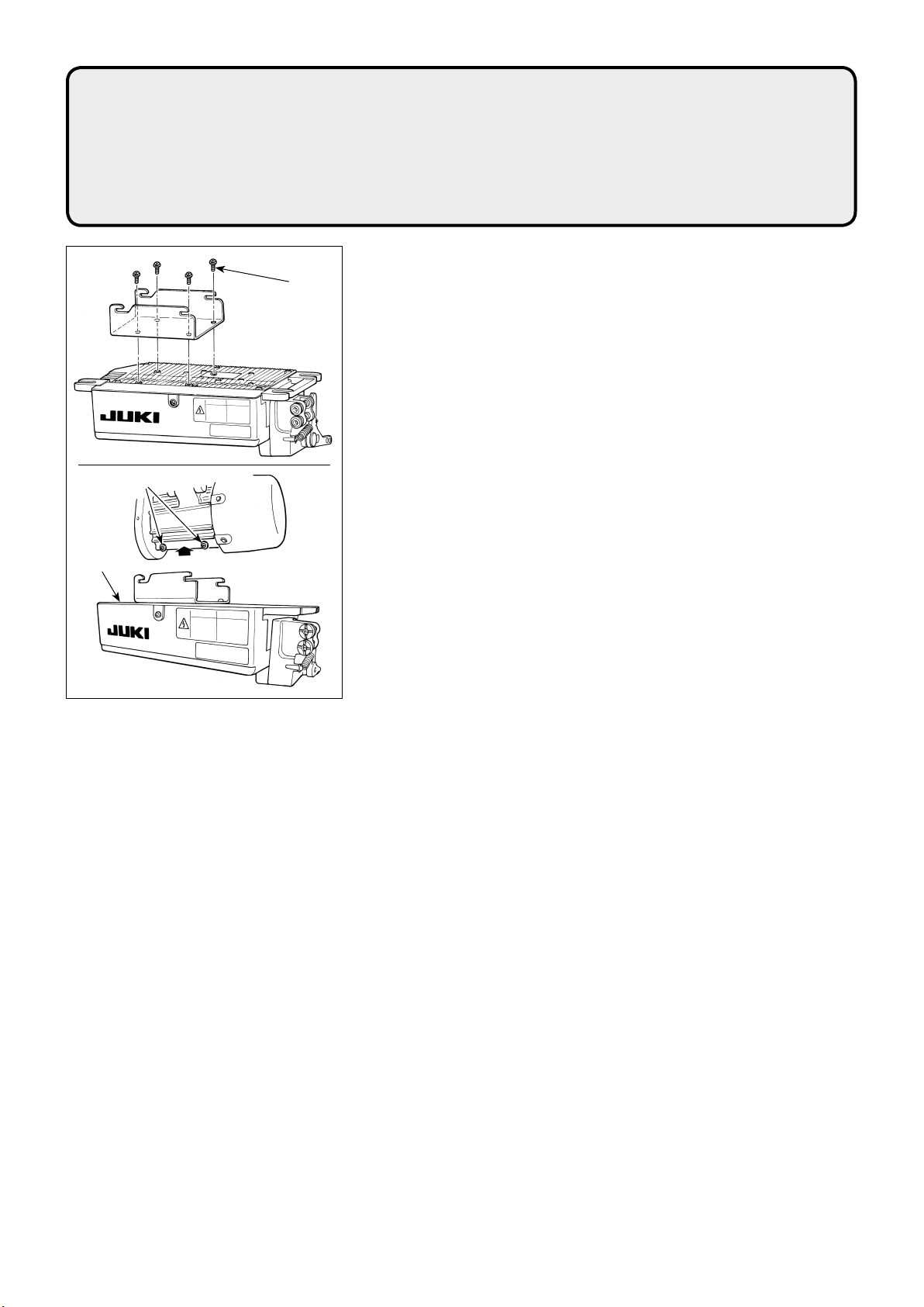
Installare l'unità di motore sul tavolo con il bullone di
montaggio asm. fornito con l'unità come accessori. Al-
lora, inserire i dadi e le rondelle forniti con l'unità come
accessoricomemostratonellagurainmodochel'unità
dimotorepossaesseressatasaldamentesultavolo.
1) Premere i tre bullon forniti con l'unità come
accessori nel foro per bullone di sospensione del
motoreneltavoloessarli.
2) Stringere temporaneamente la rondella convessa ,
la rondella elastica ed il dado sul lato in cui
due bulloni sono attaccati.
3) Sospendere l'unità di motore alla rondella che è sta-
ta serrata temporaneamente, ed attaccare la rondel-
la convessa, la rondella elastica ed il dado all'altro
bullone sul lato opposto.
4) Dopo aver regolato la posizione di montaggio del
motore, stringere saldamente i rispettivi dadi.
Installieren Sie die Motoreinheit mit den im Lieferum-
fang der Einheit enthaltenen Befestigungsschrauben
(Einh.) am Tisch. Bringen Sie dabei die im Lieferumfang
derEinheitenthaltenenMutternundKonvexscheiben
gemäß der Abbildung an, um die Motoreinheit sicher am
Tisch zu befestigen.
1) Die im Lieferumfang der Einheit enthaltenen drei
Schrauben in die Motoraufhängungs-Schrauben-
bohrungen im Tisch einpressen und festziehen.
2) Die Muttern mitKonvexscheibeund Feder-
scheibe provisorisch auf der Seite anziehen, auf
der die zwei Schrauben angebracht sind.
3) Die Motoreinheit an die provisorisch angezogene
Unterlegscheibehängen,dannKonvexscheibe,Fe-
derscheibe und Mutter an der anderen Schraube auf
der entgegengesetzten Seite anbringen.
4) DiejeweiligenMutternnachderEinstellungder
Montageposition des Motors fest anziehen.
Poserlemoteursurlatableaveclesboulonsdexation
(ensemble) fournis comme accessoires avec le moteur.
Introduirealorslesécrousetrondellesfourniscomme
accessoiresaveclemoteurcommesurlagurede
façonquelemoteurpuisseêtrecorrectementxésurla
table.
1) Enfoncer les trois boulons fournis comme acces-
soiresaveclemoteurdanslesoricesàboulonde
suspensiondumoteurdelatableetlesxer.
2)Serrerprovisoirementlarondelleconvexe, la
rondelle grower etl’écrouducôtéoùlesdeux
boulonsontétéxés.
3) Suspendre le moteur à la rondelle provisoirement
serrée,puisposerlarondelleconvexe,larondelle
groweretl’écrousurl’autreboulonducôtéopposé.
4)Aprèsavoirréglélapositiond’installationdumoteur,
serrerlesécrousrespectifsàfond.
Instalelaunidaddemotorenlamesaconelconjunto
depernosdejaciónquesesuministranconlaunidad
como accesorios. Ahora, inserte las tuercas y arande-
lasquesesuministranconlaunidadcomoaccesorios
comoseilustraenlagurademaneraquelaunidadde
motorsepuedasujetarconseguridadenlamesa.
1)Introduzcaapresiónlostrespernosquesehan
suministrado con la unidad como accesorios en el
agujerodelospernosdelosquecuelgaelmotoren
lamesayfíjelosconseguridad.
2)Aprieteprovisionalmentelaarandelaconvexa,
la arandela de muelle y la tuerca en el lado
donde van montados dos pernos.
3)Cuelgueelmotorenlaarandelaquesehanins-
taladosujetándolaprovisionalmente,ycoloquela
arandelaconvexa,laarandelademuelleylatuerca
en el otro perno en el lado opuesto.
4) Despuésdeajustarlaposicióndeinstalacióndel
motor, apriete con seguridad por separado cada una
de las tuercas.
用附属的安装螺栓组把马达装置安装到机台上。此时 ,
请按照图示插入附属的螺母、垫片并拧紧固定。
1)把附属的 3 根螺栓按进机台的吊马达螺栓孔里 , 并固
定。
2)把附属的凸垫片、弹簧垫、螺母暂时固定到 2
根螺栓侧。
3)把马达装置装到刚才暂时固定的凸垫片 , 然后把垫片、
弹簧垫、螺母安装到另一侧的 1 根螺栓上。
4)调整好马达的安装位置后 , 拧紧各个螺母。
Üniteyle birlikte aksesuar olarak temin edilen tespit
cıvatasıgrubunukullanarakmotorünitesinimasaya
monteedin.Şimdiüniteylebirlikteaksesuarolarak
teminedilensomunlarıvepullarışekildegösterildiğigibi
takarakmotorünitesinisağlambirşekildemasayatespit
edin.
1)Üniteylebirlikteaksesuarolarakteminedilenüçcı-
vatayı,masadakimotoraskıcıvatasıdeliğineitin.
2) Konveks pulu ,yaylıpuluve somunu , iki
cıvatanıntakılıolduğutaraftageçiciolaraksıkın.
3)Motorünitesinigeçiciolaraksıkılmışolanpulaasın;
konvekspulu,yaylıpuluvesomunukarşıtaraftaki
diğersomunatakın.
4)Motorunmontajkonumunuayarladıktansonrailgili
somunlarısıkın.
Установитеэлектромоторнастолеспомощьюустановочногоболта,поставляемогосмашинойвкачествепринадлеж-
ности.Вэтовремявставьтегайкиишайбы,поставляемыесмашинойвкачествепринадлежностей,какпоказанона
рисункетак,чтобыэлектромоторможнобылонадежнозакрепитьнастоле.
1)Вставьтетриболтапоставляемыесмашинойвкачествепринадлежностейвотверстиядляболтов,удерживаю-
щихэлектромоторвподвешенномсостоянии,встолеизатянитеих.
2)Временнозатянитевыпуклуюшайбу,пружиннуюшайбуигайкусостороны,гдеприкрепленыдваболта.
3)Подвесьтеэлектромоторспомощьюшайбы,котораябылавременнозатянута,иприкрепитевыпуклуюшайбу,пру-
жиннуюшайбуигайкукдругомуболтунапротивоположнойстороне.
4)Послерегулировкиположенияустановкиэлектромотора,надежнозатянитесоответствующиегайки.

– 3-1 –
/ Installing the control box /
InstallierendesSchaltkastens/Posedelaboîtedecommande/
Para instalar la caja de control /
Installazione della centralina di controllo /
电气箱的安装 / Kontrol panelinin monte edilmesi /
Установка блока управления
1)付属しているブラケットを付属のねじ(M5×10)4 本にて図
のように取り付けてください。
2)モータユニット付属のねじ4 ヶ所をゆるめて、電装ユニット
をねじに引っ掛けてからねじを締めて電装ユニットを固定して
ください。
1) Attach bracket supplied with the unit using four supplied screws
(M5×10)asshowninthegure.
2) Loosen four screws supplied with the motor unit as accessories,
tighten screws afterhangingcontrolboxunitto the screws,
andxcontrolboxunit.
1) Die mit der Einheit gelieferte Halterung mit vier mitgelieferten
Schrauben (M5 × 10) befestigen, wie in der Abbildung gezeigt.
2) Die im Lieferumfang der Motoreinheit enthaltenen vier Schrauben
lösen, dann die Schrauben anziehen, nachdem die Schaltkasten-
einheit an die Schrauben gehängt worden ist, und die Schaltka-
steneinheit befestigen.
1)Fixerlesupportaccompagnantlamachineàl’aidedesquatrevis
fournies(M5×10)commeindiquésurlagure.
2)Desserrerlesquatrevisfournies comme accessoires avec le mo-
teur, serrer les vis après avoir suspendu la boîte de commande
auxvis,puisxerlaboîtedecommande.
1)Instalelaménsulasuministrada con la unidad, utilizando para ello los cuatro tornillos (M5 × 10) suministra-
dos,talcomosemuestraenlagura.
2)Aojeloscuatrotornillosquesehansuministradoconelmotorcomoaccesorios,aprietebienestostornillos
despuésdecolgarenlostornilloslaunidaddelacajadecontrol,ysujetebienlaunidaddelacajadecon-
trol .
1) Fissare la staffa indotazioneconl'unitàconlequattrovitiindotazione(M5×10)comemostratoingura.
2)Allentarelequattrovitifornite con l'unità di motore come accessori, stringere le viti dopo aver sospeso
l'unità di centralina di controllo alleviti,essarel'unitàdicentralinadicontrollo.
1)请按照图示那样用 4 个附属的螺丝 (M5×10) 把附属的支架安装起来。
2)拧松马达装置附属的螺丝(4 处 ), 把电气箱装到螺丝上之后 , 拧紧螺丝, 然后再固定好电气箱。
1) Üniteyle birlikte temin edilen braketi ,teminedilenvidalarıkullanarak(M5×10)şekildekigibitakın.
2)Motorünitesiylebirlikteaksesuarolarakteminedilendörtvidayıgevşetin,kontrolpaneliünitesinividalara
astıktansonravidalarısıkıpkontrolpaneliünitesinitespit edin.
1)Прикрепитескобу,поставляемуюсустройством,спомощьючетырехприлагаемыхвинтов(M5×10),какпоказа-
нонарисунке.
2) Ослабьтечетыревинта,поставляемыесэлектромоторомкакпринадлежности,затянитевинтыпослеподве-
шиванияблокауправлениянавинтах,изафиксируйтеблокуправления.

– 4-1 –
/ Installing the reactor box /
InstallierendesDrosselkastens/Installationduboîtierdecommande/
Instalación de la caja del reactor / Installazione della centralina reattore /
扼流圈箱的安装 /Reaktörkutusununtakılması/
Установка реакторной коробки
1) SC-921 の電源コードの端子をリアクタボック
ス基板組およびリアクタボックス取付板に取り
付けます。
茶の電線はリアクタボックス基板組上の端子台の
上から1番目に、青の電線は3番目にそれぞれね
じ止めします。緑 / 黄の電線は、アース止めねじ
でリアクタボックス取付板に取り付けます。
2) SC-921 の電源コードにケーブルクリップを取
り付け、ケーブルクリップ止めねじでケーブルク
リップごと電源コードをリアクタボックス取付板
に取り付けます。
3) リアクタボックスの入出力ケーブルにコード
ブッシュを取り付けます。
4) リアクタボックスカバー止めねじ4本で、リアク
タボックスカバーをリアクタボックス取付板に
取り付けます。
この際、入出力ケーブルに取り付けたコード
ブッシュをリアクタボックスカバーの凹部に固
定し、リアクタボックスのすき間ができないよう
にしてください。
WARNING :
Be sure to install the reactor box after turning the power OFF.
WARNUNG :
InstallierenSiedenDrosselkastenunbedingterstnachdemAusschaltenderStromversorgung.
AVERTISSEMENT :
Veillezàcouperl'alimentationavantd'installerleboîtierdecommande.
ADVERTENCIA :
Asegúrese de desconectar la corriente eléctrica antes de instalar la caja del reactor.
AVVERTIMENTO :
Assicurarsidispegnerel'unitàprimadiinstallarelacentralinareattore.
警告 :
安装扼流圈箱时,请必须关闭(OFF)电源之后再进行安装。
UYARI :
ReaktörkutusunugücüKAPALIkonumagetirdiktensonrataktığınızdaneminolun.
ПРЕДУПРЕЖДЕНИЕ :
Убедитесь, что установили реакторную коробку после отключения электропитания.
A
B
C

– 4-2 –
* For the EU-type models, install the reactor box
that is supplied with the sewing machine.
1) Connect the terminals of power cord of the SC-
921toreactor-boxPCBasm.andtoreactorbox
mounting plate .
Connect brown wire Atotherstconnectorand
blue wire Bto the third connector respectively from
thetopofterminalblockonthereactorboxPCB
asm. using screws. Connect green/yellow wire Cto
reactorboxmountingplatewith earth setscrew
.
2) Attach cable clip to the power cord of SC-921.
Attach the power cord together with the cable clip
toreactorboxmountingplatewith cable clip
setscrew .
3) Attach cord bushes to input/output cables and
ofthereactorbox.
4) Attachreactorboxcovertoreactorboxmounting
plate withfourreactor-boxcoversetscrews.
Atthistime,xcordbushesattached to input/
output cables and in the concave section on
reactorboxcoverto eliminate a gap between
reactorboxand cover .
* Für die Modelle des EU-Typs installieren Sie den
mitderNähmaschinegeliefertenDrosselkasten.
1) Schließen Sie die Klemmen des Stromversorgungs-
kabels des SC-921 an die Drosselkasten-Plati-
neneinheit und an die Drosselkasten-Montage-
platte an.
Schließen Sie das braune Kabel Aan die erste
Klemme und das blaue Kabel Ban die dritte Klem-
mevonderOberseitedesKlemmenblocksjeweils
mit Schrauben an der Drosselkasten-Platinenein-
heit an. Schließen Sie das grün/gelbe Kabel Cmit
einer Erdungsklemmschraube an die Drossel-
kasten-Montageplatte an.
2) Bringen Sie den Kabelbinder am Stromversor-
gungskabel des SC-921 an. Befestigen Sie das
Stromversorgungskabel zusammen mit dem Ka-
belbinder mit der Kabelbinder-Befestigungsschrau-
be an der Drosselkasten-Montageplatte .
3) Bringen Sie Kabeltüllen an den Ein-/Ausgangs-
kabeln und des Drosselkastens an.
4) Befestigen Sie die Drosselkastenabdeckung mit
vier Befestigungsschrauben an der Drosselkas-
ten-Montageplatte .
Setzen Sie dabei die an den Ein-/Ausgangskabeln
und angebrachten Kabeltüllen in die Ver-
tiefungen der Drosselkastenabdeckung ein, um
einen Spalt zwischen Drosselkasten und Abde-
ckung zu beseitigen.
*Pourlesmodèlespourl’Europe,installerlaboîte
duréacteuraccompagnantlamachineàcoudre.
1) Raccordez les connecteurs du cordon d'alimenta-
tion delaSC-921àlacartedecircuitimprimédu
boîtier de commande etàlaplatinedexation
du boîtier de commande .
RaccordezlelbrunAau premier connecteur et le
lbleuBau troisième connecteur respectivement
en partant du haut du bornier de la carte de circuit
impriméduboîtierdecommandeàl'aidedevis.
Raccordezlelvert/jauneCàlaplatinedexation
du boîtier de commande à l'aide de la vis de
terre sans tête .
2) Installez l'attache-câble sur le cordon d'alimen-
tationdelaSC-921.Fixezlecordond'alimentation
etl'attache-câbleensemblesurlaplatinedexation
du boîtier de commande avec la vis sans tête
pour attache-câble .
3) Installezlesbaguesd'étanchéitésur les câbles
d'entrée/sortieet du boîtier de commande.
4) Fixezlecouvercleduboîtierdecommandesur
laplatinedexationduboîtierdecommandeà
l'aidedesquatrevisdexationsanstêtepré-
vues à cet effet.
Lorsdecetteétape,placezlesbaguesd'étanchéité
descâblesd'entrée/sortieet dans la partie
concave du couvercle du boîtier de commande
pouréliminerlejeuentreleboîtierdecommande
et le couvercle .
A
B
C

– 4-3 –
* Per i modelli progettati per l'UE, installare la cen-
tralina reattore che viene fornita con la macchina
per cucire.
1) Collegare i terminali del cavo di alimentazione
della SC-921 alla scheda a circuito stampato asm.
della centralina reattore e alla piastra di mon-
taggio della centralina reattore.
CollegareillomarroneA al primo connettore e il
lobluBal terzo connettore rispettivamente dalla
parte superiore della morsettiera sulla scheda a
circuito stampato asm. della centralina reattore
usandoleviti.Collegareilloverde/gialloCalla
piastra di montaggio della centralina reattore con
lavitedissaggiodellamessaaterra.
2) Attaccare il fermacavo al cavo di alimentazione
della SC-921. Fissare il cavo di alimentazione in-
sieme con il fermacavo alla piastra di montaggio
dellacentralinareattoreconlavitedissaggiodel
fermacavo .
3) Attaccare i gommini per cavo ai cavi e di
ingresso/uscita della centralina reattore.
4) Fissare il coperchio della centralina reattore alla
piastra di montaggio della centralina reattore con
lequattrovitidissaggiodelcoperchiodellacentra-
lina reattore .
Inquestomomento,ssarebeneigomminiper
cavo attaccati ai cavi e di ingresso/uscita nel-
la sezione concava sul coperchio della centralina
reattore in modo da eliminare la distanza tra la
centralina reattore e il coperchio .
※ EU 规格时,请安装附属的扼流器箱。
1)把 SC-921 的电源线端子安装到扼流圈箱电路板组
件和扼流圈箱安装板上。
褐色电线 A固定到扼流圈箱电路板组件从上数的第
1 个端子,蓝色电线 B固定到第 3 个端子。绿/黄色
电线 C用地线固定螺丝安装到扼流圈箱安装板上。
2)把电缆线夹安装到 SC-921 电源线,然后用电缆线
夹固定螺丝把各个电缆线夹和电源线安装到扼流圈
箱安装板。
3)把电线套安装到扼流圈箱的输出输入电缆上。
4)用 4 个扼流圈箱护罩固定螺丝把扼流圈箱护罩安
装到扼流圈箱安装板。
此时,应把安装到输出输入电缆的电线套固定
到扼流圈箱护罩的凹部,以便扼流圈箱没有间隙。
*ABtipimodelleriçindikişmakinesiilebirliktever-
ilenreaktörkutusunumonteedin.
1) SC-921'in güç kablosunun terminallerini reaktör
kutusuPCBtertibatınavereaktörkutusumontaj
plakasınabağlayın.
Vidalarıkullanarak,reaktörkutusuPCBtertibatı
üzerindekiterminalbloğununilkkonektörünekah-
verengi Akablosunu, üçüncü konektörüne de mavi
renkli B konektörünebağlayın.Yeşil/sarıCkablo-
sunu,topraklamatespitvidasıylareaktör kutusu
montajplakasınabağlayın.
2) Kablo klipsini SC-921'ingüçkablosunatakın.
Güç kablosunu kablo klipsiyle birlikte, kablo klipsi
tespitvidasıyla,reaktörkutusumontajplakasına
takın.
3) Reaktörkutusunungiriş/çıkışkablolarına(ve )
kablohalkalarınıtakın.
4) Reaktörkutusukapağını, dört adet reaktör kutu-
sukapağıtespitvidasıyla,reaktörkutusumontaj
plakasınatakın.
Buaşamada,reaktörkutusuvekapağı
arasındaboşlukkalmamasıiçinkablohalkalarını
reaktörkutusukapağınıniç bükey bölümü
üzerindekigiriş/çıkışkablolarınave takın.
* Para los modelos tipo UE, instale la caja del reac-
tor que se suministra con la máquina de coser.
1) Conectelosterminalesdelcabledealimentación
deSC-921alcjto.detableroPCBdelacaja
delreactoryalaplacademontajedelacajadel
reactor.
Conecte,conlostornillos,elconductormarrónA
al primer conector y el conductor azul Bal tercer
conector, respectivamente, ambos vistos desde la
partesuperiordelbloqueterminaldelcjto.detable-
roPCBdelacajadelreactor.Conecteelconductor
verde/amarillo Calaplacademontajedelacaja
delreactorutilizandoeltornillodejaciónatierra
.
2) Coloqueelsujetacablealcabledealimentación
deSC-921.Fijeelcabledealimentaciónjuntocon
elsujetacablealaplacademontajedelacaja
delreactorconeltornillodejacióndelsujetaca-
ble.
3) Coloquelosbujesa los cables de entrada/salida
y delacajadelreactor.
4) Instale la cubierta delacajadelreactorenla
placademontajedelacajadelreactor,utilizan-
doloscuatrotornillosdejaciónde la cubierta
delacajadelreactor.
Luego,jelosbujes,quesecolocaronalos
cables de entrada/salida y ,enlaseccióncón-
cava de la cubierta delacajadelreactor,para
eliminarelhuelgoentrelacajadelreactory la
cubierta .

– 4-4 –
* Электроблок для моделей стран ЕС поставляется со
швейной машиной.
1) ПодсоединитеклеммышнураэлектропитанияизSC-
921ккомплектупечатныхплатреакторнойкоробкии
кмонтажнойпластинереакторнойкоробки.
ПодсоединитекоричневыйпроводАкпервомуразъему
исинийпроводBктретьемуразъемусоответственно
отверхаклеммной колодки на наборе печатных плат
реакторнойкоробки,используя винты. Подсоедините
зеленый/желтыйпроводCкмонтажнойпластинере-
акторнойкоробки с помощью установочного винта
заземления.
2) Присоединитезажимшнуракшнуруэлектропитания
SC-921.Присоедините шнур электропитаниявместе
сзажимом шнура к монтажной пластине реакторной
коробкиустановочнымвинтомдлязажимашнура.
3) Присоединитекабельныевводыкпроводамвхода/
выходаиреакторнойкоробки.
4) Присоединитекожухреакторнойкоробкикмонтажной
пластинереакторнойкоробкичетырьмяустановоч-
нымивинтамидлякожухареакторнойкоробки.
Приэтом,закрепитекабельныевводы,присоединен-
ныекпроводамввода/выводаиввогнутойсекции
накожухереакторнойкоробке,чтобыустранитьзазор
междуреакторнойкоробкойикожухом.
5)脚卓前端から 200mm 位の位置を目安に、付属の
木ねじ4 本で、リアクタボックスを脚卓に取
り付けます。
組み付け位置は脚卓の大きさにより調整し、脚卓か
らはみ出ないようにしてください。
6) FAN コードのコネクタを SC-921 の CN62 に
挿入します。
7) リアクタボックスの入出力ケーブルは、付属
のコードステップルを使用して脚卓に固定してく
ださい。
この際、入出力線が互いに交差しないようにしてく
ださい。
5) Installreactorboxon the table stand with four
accessory wood screws at the position that is
approximately200mmawayfromthefrontendof
table stand.
Adjusttheinstallingpositionaccordingtothesizeof
tablestandsothatthereactorboxdoesnotpro-
trude from the edge of table stand.
6) Insert the connector of FAN cord to CN62 of the
SC-921.
7) Fixinput/outputcablesand ofreactorbox
on the table stand using accessory cord staple .
At this time, take care not to cross the input- and
output-cables.
A
B
C
SC-921 : CN62
←
/ Operator's side / Bedienerseite /
Côté opérateur / Lado del operador /
Lato operatore / 操作者一侧 /
Kullanıcıtarafı/Сторона оператора
/ Power box /
Netzanschlusskasten/
Boîtierd'alimentation/
Caja de alimentación /
Centralina di alimentazione /
电源箱/Güçkutusu/
Коробка электропитания
200 mm
SC-921
CN62
/ Undersurface of table /
Unterseite des Tisches / Dessous du support /
Cara inferior de la mesa /
Supercieinferioredeltavolo/台座背面 /
Masanınaltyüzeyi/Нижняя поверхность стола

– 4-5 –
5) Installieren Sie den Drosselkasten mit vier mit-
gelieferten Holzschrauben am Tischständer, und
zwar an der Position, die ungefähr 200 mm Abstand
vom Vorderende des Tischständers hat.
Passen Sie die Montageposition der Größe des
Tischständers an, so dass der Drosselkasten nicht
über den Rand des Tischständers hinausragt.
6) Führen Sie den Steckverbinder des Gebläsekabels
in den Anschluss CN62 des SC-921 ein.
7) Befestigen Sie die Ein-/Ausgangskabel und
des Drosselkastens mit den mitgelieferten Ka-
belkrampen am Tischständer.
Achten Sie dabei darauf, dass sich die Ein- und
Ausgangskabel nicht überkreuzen.
5) Fixezleboîtierdecommandesur le support
aveclesquatrevisàboisoptionnellesà environ
200 mm du bord avant du support.
Ajustezlapositiond'installationenfonctiondela
tailledusupportanqueleboîtierdecommandene
dépassepasduborddusupport.
6) Insérerleconnecteurducordonduventilateur
sur CN62 de SC-921.
7) Fixezlescâblesd'entrée/sortieet du boîtier
de commande sur le support à l'aide du cavalier
optionnel .
Lorsdecetteétape,veillezànepascroiserles
câblesd'entrée/sortie.
5) Instalelacajadelreactorsobre el pedestal de la
mesa con los cuatro tornillos accesorios de rosca
para madera ,enlaposiciónqueseencuentrea
aproximadamente200mmdesdeelextremofrontal
del pedestal de la mesa.
Ajustelaposicióndeinstalacióndeacuerdoconel
tamañodelpedestaldelamesa,demodoquela
cajadelreactornosobresalgadelbordedelpedes-
tal de la mesa.
6) Inserte el conector del cable del ventilador (FAN)
a CN62 de la SC-921.
7) Fijeloscablesdeentrada/saliday delacaja
del reactor sobre el pedestal de la mesa, utilizan-
do la grapa accesoria de cable.
En este paso, tenga cuidado para no cruzar los
cables de entrada y salida.
5) Installare la centralina reattore sul supporto da
tavolo a circa 200 mm dall'estremità anteriore del
supportodatavoloconlequattrovitiperlegno
accessorie .
Regolare la posizione di installazione in base alle
dimensioni del supporto da tavolo in modo che la
centralina reattore non sporga dal bordo del sup-
porto da tavolo.
6) Inserire il connettore del cavo della ventola al
CN62 della SC-921.
7) Fissare i cavi e di ingresso/uscita della centra-
lina reattore sul supporto da tavolo con il chiodo
ad U per cavo accessorio .
Inquestomomento,fareattenzioneanonincrocia-
re il cavo di ingresso con il cavo di uscita.
5)用 4 个附属木螺丝把扼流圈箱安装到距离脚桌前
端 200mm 左右的脚桌位置。
组装位置需要根据脚桌的大小进行调整,不让让它从
脚桌突出。
6)把 FAN 电线的连接器插入到 SC-921 的 CN62 里。
7)对于扼流圈箱的输出输入电缆,请使用附属的
电线台座固定到脚桌。
此时,请注意输出输入线不能相互交叉。
5) Установитереакторнуюкоробкунаоснованиидлястолачетырьмядополнительнымишурупамивположении,
котороебудетнаходитьсяприблизительнонарасстояниив200ммотпереднейчастиоснованиядлястола.
Наладьтеустановочноеположениесогласноразмеруоснованиядлястолатак,чтобыреакторнаякоробканевысту-
палаоткраяоснованиядлястола.
6) ВставьтеконнекторпроводавентиляторавразъёмCN62SC-921.
7) Прикрепитепроводаввода/выводаиреакторнойкоробкинаоснованиидлястола,используядополнитель-
нуюскобудляшнура.
Приэтомпозаботьтесь,чтобыпроводавхода/выходанепересекались.
5) Reaktör kutusunu aksesuar olarak verilen dört
ahşapvidayıkullanarakmasastandıüzerine,
masastandınınönucundanyaklaşık200mmuzak-
takibirkonumatakın.
Reaktörkutusununmasastandınınkenarındandı-
şarıçıkmamasıiçinmontajkonumunumasaboyu-
tunagöreayarlayın.
6) Fan kablosunun konektörünü SC-921’in CN62
nolukonektörünetakın.
7) Reaktör kutusunun giriş/çıkışkablolarınıve
,aksesuarolarakverilenkablozımbasınıkulla-
narakmasanınüzerinesabitleyin.
Buaşamada,girişveçıkışkablolarınıkarıştırmama-
ya dikkat edin.

– 5-1 –
15 mm (9.8 N)
1) ミシンプーリとモータプーリの間にベルトを平行に取り付けます。
2) ベルトの張力は張力調整ナットを回してモータの高さを調整し、ベ
ルトが中心部を手で押した時、約 15mm(9.8N) 程度沈むように調整
します。
ベルトの張力が十分でない場合は、中低速でミシンを操作した場合、
回転にムラが生じたり、針が正確な位置で停止しない場合があります。
1) The belt distance, between sewing machine pulley and motor pulley,
must be parallel.
2) Thebelttensionshouldbeadjustedbyturningthetensionadjustnuts
to change height of the motor, so that the belt sinks down by about 15
mm (9.8 N) when it is depressed by band at the center of the belt span.
If the belt tension is not tight, speed is unstable at low-speed or medi-
um-speedoperation,andtheneedlewillnotstopexactlyinposition.
1) Der Riemenabstand zwischen der Nähmaschinen-
riemenscheibe und der Motorriemenscheibe muss
parallel sein.
2) Die Riemenspannung ist durch Drehen der Span-
nungseinstellmuttern zur Höhenverstellung des
Motors so einzustellen, dass der Riemen um etwa
15 mm/9,8 N nachgibt, wenn er in der Mitte der Rie-
menspanne mit der Hand eingedrückt wird.
Falls der Riemen zu locker ist, hat dies Laufschwan-
kungen bei Betrieb mit geringer oder mittlerer
Geschwindigkeit und eine ungenaue Nadelstopppo-
sition zur Folge.
1) Les brins de courroie entre la poulie de la machine
et la poulie du moteur doivent être parallèles.
2)Ondoitréglerlatensiondelacourroieentournant
lesécrousderéglagedetensionpour changer la
hauteurdumoteurdefaçonquelacourroiepré-
senteuneèche(déplacementverslebas)d’environ
15mm/9,8Nlorsqu’onappuieaveclamainau
centre du brin de courroie.
Si la courroie est mal tendue, la vitesse sera ins-
table lors d’un fonctionnement à petite ou moyenne
vitesse et l’aiguille ne s’arrêtera pas sur une position
précise.
1)Ladistanciadelacorrea,entrelapoleadelamáqui-
na de coser y el motor debe de ser paralela.
2)Latensióndelacorreasedeberáajustargirandolas
tuercasdeajustedetensiónpara cambiar la altu-
radelmotor,demodoquelacorreasehundaunos
15 mm (9,8 N) cuando se presiona con la mano en
el centro del tramo de la misma.
Silatensióndelacorreanoestátensa,lavelocidad
seráinestablecuandoseoperaabajavelocidadoa
velocidadmedia,ylaagujanosepararáenlaposi-
ciónexacta.
1) La distanza della cinghia, tra la puleggia della
macchina per cucire e la puleggia del motore, deve
essere parallela.
2) La tensione della cinghia deve essere regola-
ta girando i dadi di regolazione della tensione
per cambiare l'altezza del motore, in modo che la
cinghiasiabbassidicirca15mm/9,8Nquandola
cinghia viene premuta con la mano al centro dell'e-
stensione della cinghia. Se la tensione della cinghia
non è giusta, la velocità è instabile al funzionamen-
to a bassa velocità o media velocità, e l'ago non si
fermerà esattamente in posizione.
1)皮带长度必须大于缝纫机皮带轮和马达皮带轮。
2)调整张力调节螺母改变马达的高度可以调整皮
带张力 , 用手按压皮带中央处 , 皮带垂度应为
15mm(9.8N)。如果皮带张力过松 , 缝制速度就会降低 ,
或中速缝制时速度不稳定 , 因此缝纫机针就有可能不
能准确地停止到指定位置。
1) Dikişmakinesikasnağıilemotorkasnağıarasında-
kikayışmesafesiparalelolmalıdır.
2) Motoryüksekliğinideğiştirmekiçin,gerginlikayar
somunlarınıçevirerekkayışgerginliğiayarlan-
malıdır;kayışuzunluğununortasınaellebastırıldığı
zamanyaklaşık15mm(9,8N)çökmesigerekir.
Kayışgergindeğilse,düşükyadaortahızlaçalı-
şırkenhızkararsızolurveiğnetamolarakdurması
gereken yerde durmaz.
1)Расстояниеприводногоремня,междушкивомшвейноймашиныимоторнымшкивом,должнобытьодинаковым
(ременьдолженрасполагатьсяпараллельно).
2)Натяжениеприводногоремнядолжнобытьотрегулировано,приповорачиваниигайки,регулирующейнатяжение,
чтобыизменитьвысотуэлектромотора,так,чтобыприводнойременьопустилсяприблизительнона15мм(9,8Н),
когданадавитенанегорукойвсередине.Еслинатяжениеприводногоремнянедостаточное,скоростьбудетнепо-
стояннойприработевмедленномилисреднескоростномрежиме,иигланебудетостанавливатьсяточновопреде-
ленномположении.
/ Installing the belt / Installieren des Riemens /
Pose de la courroie / Cómo ajustar la cubierta de la polea /
Installazione della cinghia / 安装皮带/Kayışıntakılması/
Установка приводного ремня

– 6-1 –
1)ベルト張力調整後、ベルトとプーリカバーのとのす
き間が同じになるように、プーリカバーを調整します。
2)調整終了後、プーリカバーの横にあるねじを締めて、プー
リカバーがずれないようにしっかりと固定します。
1) Afteradjustingthebelttension,adjustthepulleycoverso that
the clearances between the belt and the pulley cover ,
and should be the same.
2) Afterthecompletionofadjustment,tightenscrewslocated on
the side of pulley cover andsecurelyxthepulleycoverso
that it does not slip out of position.
1) Die Riemenscheibenabdeckung nach der Einstellung der
Riemenspannung so einstellen, dass die Abstände und
zwischen dem Riemen und der Riemenscheibenabdeckung
gleich sind.
2) Nach Abschluss der Einstellung die Schrauben auf der Seite
der Riemenscheibenabdeckung anziehen, und die Riemen-
scheibenabdeckung sicher befestigen, damit sie nicht ver-
rutscht.
/ Adjusting the pulley cover/
EinstellenderRiemenscheibenabdeckung/
Réglage du couvercle de poulie / Cómo ajustar la cubierta de la polea /
Regolazione del coperchio della puleggia / 调整皮带轮护罩 /
Kasnakkapağınınayarlanması/Регулировка кожуха шкива
1) Aprèsavoirréglélatensiondelacourroie,réglerlecouvercledepouliedefaçonquelesjeuxet entre
la courroie et le couvercle de poulie soientégaux.
2) Aprèsleréglage,serrerlesvissituéessurlecôtéducouvercledepoulieetxersolidementlecouvercle
defaçonqu’ilnesedélogepas.
1) Despuésdeajustarlatensióndelacorrea,ajustelacubiertadelapoleademodoquelasseparacionesen-
tre la correa y la cubierta de la polea, y , sean las mismas.
2) Despuésdecompletarelajuste,aprietelostornillosubicados en el lado de la cubierta delapoleayje
con seguridad la cubierta delapoleademodoquenosesalgadesuposición.
1) Dopo aver regolato la tensione della cinghia, regolare il coperchio della puleggia in modo che le distanze tra
la cinghia e il coperchio della puleggia , e siano gli stessi.
2) Dopo il completamento della regolazione, stringere le viti poste sul lato del coperchio della puleggia e
ssaresaldamenteilcoperchiodellapuleggiain modo che esso non scivoli via dalla posizione.
1)调整完皮带张力之后 , 请调整皮带轮护罩, 把皮带和皮带轮护罩的间隙 和调整成相等。
2)整个调整都结束之后 , 拧紧皮带轮护罩侧的螺丝, 安装时应注意皮带轮护罩中的皮带不要从皮带轮上脱落
下来。
1)Kayışgerginliğiniayarladıktansonrakasnakkapağınıayarlayın;kayışilekasnakkapağıarasındakive
boşluğuaynıolmalıdır.
2)Ayarbittiktensonra,kasnakkapağınınyanındakividalarısıkınveyerindenkaymamasıiçinkasnakkapağı-
nısıkıcatespitedin.
1)Послерегулировкинатяженияприводногоремня,отрегулируйтеположениекожухашкиватак,чтобызазоры
междуприводнымремнемикожухомшкива,идолжныбытьодинаковыми.
2)Послезавершениярегулировки,затянитевинты,расположенныенасторонекожухашкива,инадежноза-
фиксируйтекожухшкиватак,чтобыонневыскальзывализэтогоположения.

– 7-1 –
巻き込み防止ピンを取り付けるに
は、ミシンの回転方向に従ってモー
タプーリカバーの取付穴 か
を選択し、付属品のねじと座金
を使って選択した穴にピンを取り付
けてください。
a) 方向にモータが回転する場合:
→取付穴 に巻き込み防止ピン
を取り付けます。
b) 方向にモータが回転する場合:
→取付穴 に巻き込み防止ピン
を取り付けます。
/
Installation and adjustment for the protecting pin and the belt slip-off
preventingbracket/
Installation und Einstellung des Schutzstifts und des Riemenfangbügels /
Pose et réglage de l’ergot de protection et du support anti-délogement
de la courroie /
Instalación y ajuste para el pasador de protección y para la ménsula
protectora de deslizamiento hacia afuera de la correa /
Installazione e regolazione per il perno di protezione e il supporto di
prevenzionedellolamentodellacinghia/
安装并调整保护销和防止皮带脱落的支架 /
Koruyucupiminvekayışınkaymasınıönleyenbraketinkurulumuveayarı/
Установка и регулировка предохранительного штифта и скобы, предотвращающей
соскальзывание приводного ремня
WARNING :
Topreventpersonalinjurycausedbyabruptstartofthesewingmachine,carryoutthework
after turning OFF the power switch and ascertaining that the motor has completely stopped.
WARNUNG :
Schalten Sie vor Beginn der Arbeit die Stromversorgung aus, um durch plötzliches Anlaufen
der Nahmaschineverursachte Unfälle zu verhüten.
AVERTISSEMENT :
Pour ne pas risquer des blessures causées par une brusque mise en marche de la machine,
toujours placer l'interrupteur d'alimentation sur arrêt et s'assurer que le moteur est complè-
tement arrêté avant d'effectuer cette opération.
ADVERTENCIA :
Desconecte la corriente eléctrica y asegúrese que el motor se haya detenido completamente
antes de comenzar el trabajo para evitar accidentes causados por un arranque brusco de la
máquina de coser.
AVVERTIMENTO :
Prima di effettuare le seguenti operazioni assicurarsi di spegnere l’interruttore dell’alimenta-
zionealnedievitareincidenticausatidall’avvioimprovvisodellamacchinapercucire.
警告 :
为了防止突然起动造成人身事故,请关掉电源,确认马达确实停止转动后再进行操作。
UYARI :
Dikişmakinesininanidençalışarakyaralanmalarasebepvermemesiiçin,güçşalteriniKAPA-
LIkonumagetiripmotoruntamamendurduğundaneminolduktansonraçalışmayabaşlayın.
ПРЕДУПРЕЖДЕНИЕ :
Чтобы предотвратить травмы, вызванные внезапным запуском швейной машины, производите действия
после того, как отключите выключатель электропитания и убедитесь, электромотор полностью остановился.
A B

– 7-2 –
(1) Attaching hole for the protecting pin
To attach protecting pin , select either attaching
hole or attaching hole in the motor pulley cover
in accordance with the direction of rotation of the
sewing machine and attach the pin in the selected
hole using screw and washer supplied with the
unit.
a) If the motor shaft rotates in direction Ain the
gureontheabove:
→Attach protecting pin in attaching hole .
b) If the motor shaft rotates in direction Bin the
gureontheabove:
→Attach protecting pin in attaching hole .
(1) Montageloch für Schutzstift
WählenSiejenachderDrehrichtungderNähma-
schine entweder Montageloch oder in der
Motorriemenscheibenabdeckung zur Befestigung
des Schutzstifts , und befestigen sie den Stift mit
der im Lieferumfang der Einheit enthaltenen Schrau-
be und Unterlegscheibe in dem ausgewählten
Loch.
a) Wenn sich die Motorwelle in Richtung Agemäß
derobigenAbbildungdreht:
→Den Schutzstift im Montageloch bef-
stigen.
b) Wenn sich die Motorwelle in Richtung Bgemäß
derobigenAbbildungdreht:
→Den Schutzstift im Montageloch befesti-
gen.
(1)Oricedeposedel’ergotdeprotection
Poser l’ergot de protection dansl’oricedemon-
tage ou du couvercle de poulie de moteur
selon le sens de rotation de la machine à l’aide de la
vis et de la rondelle fournies.
a) Si l’arbre du moteur tourne dans le sens Asur la
gureci-dessus:
→Poser l’ergot de protection dansl’oricede
montage .
b) Si l’arbre du moteur tourne dans le sens Bsur la
gureci-dessus:
→Poser l’ergot de protection dansl’oricede
montage .
1) Cómo agregar el agujero para el pasador de pro-
tección
Para colocar el pasador deprotección,seleccione
yaseaelagujerooelagujeroen la cubierta de
la polea del motor en conformidad con la direc-
cióndelarotacióndelamáquinadecoserycoloque
elpasadorenelagujeroseleccionadousandoel
tornillo y la arandela quesesuministraroncon
la unidad.
a)SielejedelmotorgiraenladirecciónAcomo se
ilustraenlaguraanterior:
→Coloqueelpasadordeprotecciónenelagu-
jerodemontaje.
b)SielejedelmotorgiraenladirecciónBcomo se
ilustraenlaguraanterior:
→Coloqueelpasadordeprotecciónenelagu-
jerodemontaje.
(1)Forodissaggioperilpernodiprotezione
Per attaccare il perno di protezione , selezionare
oilforodissaggiooilforodissaggionel
coperchio della puleggia del motore secondo
il senso di rotazione della macchina per cucire ed
attaccare il perno di protezione nel foro selezionato
usando la vite e la rondella fornite con l'unità.
a) Se l'albero del motore gira in senso Anellagu-
raquisopraindicata:
→Attaccare il perno di protezione nel foro di
ssaggio.
b) Se l'albero del motore gira in senso Bnellagu-
raquisopraindicata:
→Attaccare il perno di protezione nel foro di
ssaggio.
(1) 保护销安装孔
安装保护销时 , 请根据缝纫机的转动方向选定马达
皮带轮护罩的安装孔 或安装孔 。然后再把机
器附属的螺丝和垫片, 保护销安装到被选定的安
装孔上。
a)进行上述安装时 , 如果马达轴的转动方向如图示
的方向 A时:
→把保护销安装到安装孔 上。
b)进行上述安装时 , 如果马达轴的转动方向如图示
的方向 B时:
→把保护销安装到安装孔 上。
(1)Koruyucupimiçinmontajdeliği
Koruyucu pimi takmakiçin,dikişmakinesinin
dönüşyönüneuygunolarakmotorkasnağınınkapa-
ğındakiya da montajdeliğiniseçin,üniteyle
birlikteteminedilenvidayıve pulu kullanarak
pimiseçtiğinizdeliğetakın.
a)MotormilieğeryukarıdakişekildegösterilenA
yönündedönüyorsa:
→Koruyucu pimi pimdeliğinetakın.
b)MotormilieğeryukarıdakişekildegösterilenB
yönündedönüyorsa:
→Koruyucu pimi pimdeliğinetakın.
(1) Крепежное отверстие для предохранительного штифта
Чтобыприкрепитьпредохранительныйштифт,
выберитекрепежноеотверстиеиликрепежное
отверстиевкожухешкиваэлектромоторав
соответствииснаправлениемвращенияшвейной
машиныизакрепитештифтввыбранномотверстии,
используявинтишайбупоставляемыевместес
машиной.
a)Есливалэлектромоторавращаетсявнаправлении
A,какпоказанонарисункевыше:
→Закрепитепредохранительныйштифтв
крепежномотверстии.
b)Есливалэлектромоторавращаетсявнаправлении
B,какпоказанонарисункевыше:
→Закрепитепредохранительныйштифтв
крепежномотверстии.

– 7-3 –
図のように巻き込み防止ピンとベルト外れ防止支
えの位置を調整します。
a)巻き込み防止ピンの調整
ねじをゆるめ、図の位置に巻き込み防止ピン
を取り付けます。
b)ベルト外れ防止支えの調整
ねじをゆるめ、図の位置にベルト外れ防止支
えを取り付けます。
巻き込み防止ピンが正しく調整されていない
とプーリとベルトの間に指が挟まれ、ケガ
をする場合があります。
ベルト外れ防止支えが正しく調整されていな
いと、ベルトが外れて危険な場合があります。
● 調整後、巻き込み防止ピンとベルト外れ防止支え
が振動で動かないようにねじとを締めてくだ
さい。
● ミシンを操作する前に巻き込み防止ピンとベルト
外れ防止支えがプーリおよびベルトと接触し
ないことを確認してください。
(2)Adjustmentfortheprotectingpinandthebeltslip-offpreventingbracket
Adjustthepositionofprotectingpinand belt slip-off preventing bracket inaccordancewiththegure.
a) Adjustingtheprotectingpin
Loosen screw andadjustsothatprotectingpinispositionedatthelocationindicatedinthegure.
b) Adjustingbeltslip-offpreventingbracket
Loosen screw andadjustsothatbeltslip-offpreventingbracketis positioned at the location indicated
inthegure.
If protecting pin isnotproperlyadjusted,itispossiblethatyourngersmaybecaughtintheclearance
provided between the pulley and the belt resultingininjury.Ifbeltslip-offpreventingbracketis not
properlyadjusted,itispossibletoallowthebelttoslipoffcausingsafetyhazard.
● Aftertheadjustment,tightenscrewsand so as to secure protecting pin and belt slip-off preventing
bracket topreventthesecomponentstouctuatebecauseofvibration.
●Before starting the operation of the sewing machine, ascertain that protecting pin and belt slip-off preventing
bracket do not come in contact with the pulley and the belt .
(2) Einstellung des Schutzstifts und des Riemenfangbügels
Die Position des Schutzstifts und des Riemenfangbügels gemäß der Abbildung einstellen.
a) Einstellen des Schutzstifts
Die Schraube lösen und so einstellen, dass sich der Schutzstift an der in der Abbildung gezeigten Posi-
tionbendet.
b) Einstellen des Riemenfangbügels
Die Schraube lösen und so einstellen, dass sich der Riemenfangbügel an der in der Abbildung ge-
zeigtenPositionbendet.
Falls der Schutzstift nicht richtig eingestellt wird, besteht die Gefahr, dass Ihre Finger in dem Spalt zwi-
schen der Riemenscheibe und dem Riemen eingeklemmt und verletzt werden. Falls der Riemenfang-
bügel nicht richtig eingestellt wird, besteht die Gefahr, dass der Riemen abrutscht und die Sicherheit
gefährdet.
●Nach der Einstellung die Schrauben und zur Sicherung des Schutzstifts und des Riemenfangbügels
fest anziehen, um zu verhüten, dass diese Teile sich durch Vibrationen lockern.
●Vor der Inbetriebnahme der Nähmaschine sicherstellen, dass der Schutzstift und der Riemenfangbügel
nicht mit der Riemenscheibe und dem Riemen in Berührung kommen.
C
C
D
C :
4 mm or less
4 mm oder weniger
4 mm maximum
4 mm o menos
4 mm o meno
D :
3 mm or less
3 mm oder weniger
3 mm maximum
3 mm o meno

– 7-4 –
(2) Réglage de l’ergot de protection et du support anti-délogement de la courroie.
Réglerlapositiondel’ergotdeprotectionetdusupportanti-délogementdelacourroiecomme il est in-
diquésurlagureci-contre.
a)Réglagedel’ergotdeprotection
Desserrer la vis etréglerl’ergotdeprotectionpourqu’ilsetrouvesurlapositionindiquéesurlagure
ci-contre.
b) Réglagedusupportanti-délogementdelacourroie
Desserrer la vis etréglerlesupportanti-délogementdelacourroiepourq’ilsetrouvesurlaposition
indiquéesurlagureci-contre.
Si l’ergot de protection n’estpascorrectementréglé,onrisquedeseblesserenseprenantlesdoigts
dans l’espace entre la poulie et la courroie .Silesupportanti-délogementdelacourroien’est pas
correctementréglé,lacourroierisquedesedélogeretdemettrelasécuritéendanger.
● Aprèsleréglage,serrerlesviset defaçonàxersolidementl’ergotdeprotectionet le support an-
ti-délogementdelacourroiepour empêcher ces pièces de bouger sous l’effet des vibrations.
● Avantdemettrelamachineenmarche,s’assurerquel’ergotdeprotectionetlesupportanti-délogementde
la courroie ne viennent pas en contact avec la poulie et la courroie .
(2) Ajuste del pasador de protección y de la ménsula de prevención de deslizamiento de la correa.
Ajustelaposicióndelpasadordeprotecciónydelaménsulaprotectora de deslizamiento de la correa
comoseilustraenlagura.
a)Cómoajustarelpasadordeprotección
Aojeeltornilloyhagaelajustedemodoqueelpasadordeprotecciónquedeposicionadoenellugar
indicadoenlagura.
b)Cómoajustarlaménsuladeprevencióndedeslizamientodelacorrea
Aojeeltornilloyhagaelajustedemodoquelaménsuladeprevencióncontradeslizamientodela
correaquedeposicionadaenellugarindicadoenlagura.
Si el pasador deprotecciónnoestádebidamenteajustadoexisteelpeligrodequesusdedosqueden
cazadosylesionadosenelespacioquequedaentrelapoleay la correa .Silaménsulade preven-
cióndedeslizamientodelacorreanoestádebidamenteajustada,esposiblequelacorreasesalgaponien-
do en peligro la seguridad.
● Terminadoelajuste,aprietelostornillosy demodoqueelpasadordeprotecciónquedebiensegurolo
mismoquelaménsuladeprevencióndedeslizamientodelacorreaevitandoasíqueloscomponentesuc-
túen debido a las vibraciones.
● Antesdeponerenfuncionamientolamáquinadecoser,asegúresedequeelpasadordeprotecciónyla
ménsulaqueimpideeldeslizamientodelacorreanotoquenlapoleani la correa .
(2)Regolazioneperilpernodiprotezioneeilsupportodiprevenzionedelloslamentodellacinghia
Regolare la posizione del perno di protezione edelsupportodiprevenzionedelloslamentodellacinghia
secondolagura.
a) Regolazione del perno di protezione
Allentare la vite e regolare in modo che il perno di protezione sia posizionato alla posizione indicata
nellagura.
b)Regolazionedelsupportodiprevenzionedelloslamentodellacinghia
Allentare la vite eregolareinmodocheilsupportodiprevenzionedelloslamentodellacinghiasia
posizionatoallaposizioneindicatanellagura.
Se il perno di protezione non è regolato correttamente, è possibile che le dita vengano intrappolate nello
spazio lasciato tra la puleggia e la cinghia e ne risulteranno ferimenti. Se il supporto di prevenzione
delloslamentodellacinghianonèregolatocorrettamente,èpossibileconsentireallacinghiadislarsi
causando pericoli.
●Al termine della regolazione, stringere le viti e alnediassicurareilpernodiprotezionee il supporto
diprevenzionedelloslamentodellacinghiaperprevenirelauttuazionediquesticomponentiacausadella
vibrazione.
●Prima di iniziare il funzionamento della macchina per cucire, assicurarsi che il perno di protezione e il sup-
portodiprevenzionedelloslamentodellacinghianon vengano a contatto con la puleggia e la cinghia .
Other manuals for SC-921
2
This manual suits for next models
1
Other JUKI Sewing Machine manuals

JUKI
JUKI MH-380 User manual

JUKI
JUKI MO-654DE User manual

JUKI
JUKI LK-1900A Quick start guide

JUKI
JUKI SADE User manual

JUKI
JUKI MO-6000G Series Quick start guide

JUKI
JUKI SC-510 Quick start guide

JUKI
JUKI LK-1903BR35 User manual

JUKI
JUKI LU-2216N-7 User manual

JUKI
JUKI MB-1373 User manual

JUKI
JUKI DP-2100 User manual