JUKI MB-1373 Quick start guide

40041089
No. E378-00
ENGINEER’S MANUAL
®
Single-thread, chain stitch, button sewing machine with
thread-fray- prevention ON/OFF changeover mechanism
MB-1373
MB-1377(Quick stitch-shape changing
mechanism)

PREFACE
This Engineer’s Manual is written for the technical personnel who are responsible for the service and maintenance
of the machine.
The Instruction Manual for these machines intended for the maintenance personnel and operators at an apparel
factory contains operating instructions in detail. And this manual describes "Standard Adjustment", "Adjustment
Procedures", "Results of Improper Adjustment", and other important information which are not covered in the
Instruction Manual.
It is advisable to use the relevant Instruction Manual and Parts List together with this Engineer’s Manual when
carrying out the maintenance of these machines.
This manual gives the "Standard Adjustment" on the initial page under which the most basic adjustment value is
described, and on the second page "Results of Improper Adjustment" under which stitching errors and troubles
arising from mechanical failure and described together with the "Adjustment Procedures".

CONTENTS
1. Specifications ........................................................................................................ 1
2. Standard Adjustment ............................................................................................ 2
(1) Height of the needle bar ........................................................................................................ 2
(2) Positioning the looper............................................................................................................ 2
(3) Yoke-slide timing .................................................................................................................... 4
(4) The floating timing of thread tension disc No.2.................................................................. 4
(5) Height and pressure of the button clamp ............................................................................ 6
(6) Thread tension disc No. 1...................................................................................................... 6
(7) Positioning the thread nipper ............................................................................................... 8
(8) Adjusting the stitch selecting mechanism .......................................................................... 8
(9) Positioning the stitch adjusting cam.................................................................................. 10
(10)Adjusting the stop-motion position.................................................................................... 10
(11) Positioning the stop-motion disc and the stop-motion plunger ..................................... 12
(12)Changing over the quick stitch-shape changing mechanism (MB-1377)....................... 14
(13)Positioning the feed cam ..................................................................................................... 16
(14)Positioning the button lifting link ....................................................................................... 16
(15)Positioning the needle driving pulley pressure applying lever ....................................... 18
(16)Positioning the thread pull-off lever................................................................................... 18
3. Adjustments of the Automatic thread trimmer........................................ 20
(1) The mechanism and the name of each component of the thread trimmer .................... 20
(2) Adjusting the position of the moving knife ....................................................................... 22
(3) Adjusting the height of the thread separating claw of the moving knife....................... 22
(4) Clearance between the lifting lever and the adjusting screw.......................................... 24
(5) Installing the button clamp lifting rod ................................................................................ 24
4. Adjustments of the knot-tying mechanism ............................................. 26
(1) The mechanism and the name of each component of the knot-tying feature ............... 26
(2) Adjusting the connecting plate........................................................................................... 26
(3) Adjusting the thread bind arm stopper .............................................................................. 28
(4) Adjusting the thread bind notch ......................................................................................... 28
(5) Adjusting the lever ............................................................................................................... 30
(6) Adjusting the speed slowing friction plate........................................................................ 30
5. Maintenance ............................................................................................... 32
(1) Applying the exclusive grease............................................................................................ 32
6. Troubleshooting .......................................................................................... 40
(1) Stitching troubles ................................................................................................................. 40
(2) Mechanical troubles ............................................................................................................. 42
(3) Thread trimming troubles.................................................................................................... 43
7. Table diagram ............................................................................................. 45

MEMO

– 1 –
No. MB-1373 MB-1377
1Sewing speed Normal speed 1,300 rpm (Max. 1,500 rpm )
2Number of stitches 8, 16, 32 stitches
Crosswise feed 2.5 to 6.5 mm Crosswise feed 2.5 to 6.5 mm
Lengthwise feed 0, 2.5 to 6.5 mm Lengthwise feed 0, 2.5 to 4.5 mm
4Sewing pattern changeover By changing the cam By changing over the lever position
5Stitching pattern U-shape and X-shape
6Button size 10 to 28mm
7Needle bar stroke 48.6mm
8Needle TQx1 #16 (#14 ~ #20), (TQx7 #16 (#14 ~ #20))
JUKI NEW DEFLEX OIL No.1 or JUKI MACHINE OIL No. 7
JUKI MACHINE OIL No. 7 (equivalent to ISO VG7) with an oiler
10 Grease Exclusive grease
Interlocked with the button clamp lifting mechanism.
The thread is cut by the counter knife and moving knife.
12 Provided with an ON/OFF changeover function
13 Provided as standard
14 Button clamp lifting system Automatic system (Pedal type is also available.)
15 Mass of the machine head 24kg
1. Specifications
Model name
Item
3Amount of feed
9Lubricating oil
11 Automatic thread trimmer
Quick stitch-shape
changing mechanism
Thread-fray-prevention
ON/OFF changeover
mechanism
(provided as standard)

– 2 –
2. Standard Adjustment
(1)Height of the needle bar
*The two upper engraved lines on needle bar should be used for adjustment when
using a TQx1 needle, or the two lower ones should be used when using a TQx7 needle.
Upper engraved lines Aon needle bar should be aligned with the bottom of lower bushing .
(2)Positioning the looper
1. Looper timing
The lower engraved lines on the needle bar should be aligned
with the bottom of lower bushing (when the needle bar is at its
highest position).
2. Clearance between the needle and looper
0.01 to 0.1 mm
3. Clearance between the needle guide and needle
0.05 to 0.1 mm
Engraved line
Looper’s blade point
coincides with the
center of the needle.
0.05 to 0.1mm
1. Looper timing
2. Clearance between needle
and looper
3. Clearance between the needle
guide and needle
0.01 to 0.1mm
Looper’s blade point
Standard Adjustment
Standard Adjustment
A
TQX1
TQX7
B

– 3 –
1. Depress the pedal fully forward, turn the needle driving pulley in the
normal sewing direction by hand to bring down the needle bar to
the lowest position of its stroke and loosen screw .
2. Adjust the height of the needle bar using the top two lines engraved
on needle bar for the TQx1 needle and using the bottom two
lines for the TQx7 needle. Align upper line Awith the bottom end
face of needle bar bushing (lower) and tighten screw . At this
time, tighten the screw so that groove Bof the needle faces the
front.
oIf needle bar is too high,
skipped stitches will be produced.
oIf the needle bar is too low, the
needle will come into contact with
the looper.
1. Adjusting the looper timing
Loosen two screws in the cam and looper sleeve. Then turn the
cam and looper sleeve in the rotating direction so that the looper
blade point aligns with the center of the needle when the lower
engraved lines on the needle bar are aligned with the bottom of
lower bushing . Then, tighten screws .
2. Clearance between the needle and looper
Loosen two screw in the looper support ring when the blade
point of the looper aligns with the center of the needle. Adjust so
that a clearance of 0.01 to 0.1 mm is provided between the looper
and needle. Then, tighten setscrew .
3. Clearance between the needle guide and needle
Loosen setscrew when the needle bar is in the lowest position.
Adjustso that a 0.05 to 0.1 mm clearance is provided between needle
guide and the needle and tighten setscrew .
oIf the clearance between the
needle and looper is too exces-
sive, it is likely to produce skipped
stitches. If the clearance is too
small, in accordance with the ma-
terial used, the needle will come
into contact with the looper, result-
ing in needle breakage and
looper’s blade point breakage.
oFor thick materials and overlapped
sections, adjust the clearance
between the needle guide and
needle so that the needle guide
touches the needle by 0.05 to 0.1
mm.
Adjustment Procedure Results of Improper Adjustment

– 4 –
1. Crosswise travel timing of the yoke slide
The height of ascending needle bar should be 4 to 7 mm when yoke slide begins to travel from left to
right.
2. Lengthwise travel timing of the yoke slide
The yoke slide begins to go back immediately after
the blade point of the looper has passed the thread
triangle. For the triangle movement of yoke , it is
good for yoke to go back like a slant line.
3. Lengthwise positioning of the yoke slide
Position the yoke slide so that the blade point of the
looper passes through the center of the thread
triangle.
(For four-holed buttons: Adjust so that the looper
blade point passes through the thread triangle at 9th
to 10th stitches.)
(3)Yoke-slide timing
4 to 7mm
Blade point of looper
Engraved marks
Looper
(4)The floating timing of thread tension disc No.2
The height of needle bar at the floating timing of thread tension disc No. 2 should be 44 to 47 mm.
44 to 47mm
The floating start timing is
when the thread tension is
released while the needle
bar ascends.
Phenomenon Tension release bar height
1. Thread is poorly tensed on the wrong side of the fabric. Slightly increase the height.
2. Thread breaks halfway at the time of stop-motion. Slightly decrease the height.
3. Thread frequently breaks. Slightly decrease the height.
Standard Adjustment
Standard Adjustment
B
A
0.05 to 0.1mm

– 5 –
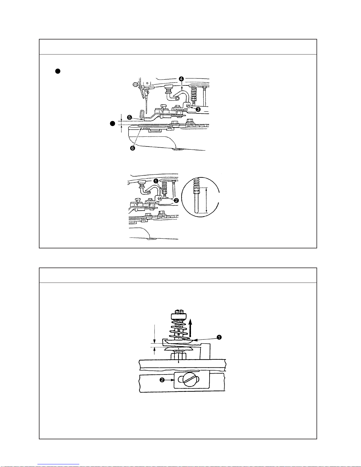
To adjust the timing of the travel of yoke slide , align the engraved
marks of loop positioning finger cam and loop positioning finger
triangular cam with the engraved mark of cam and looper sleeve
after the adjustment of the looper so that the engraved marks are in a
straight line. Then temporarily tighten the screws.
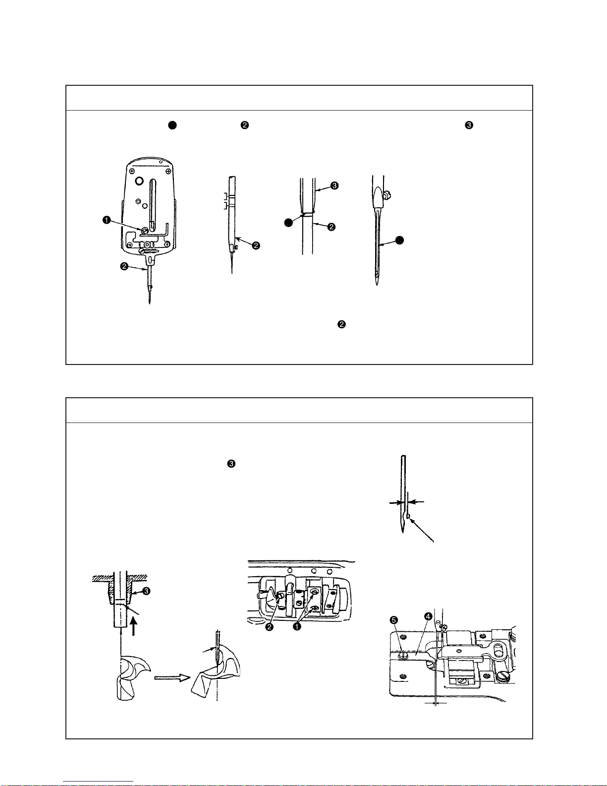
1. For the lateral-motion timing of yoke slide , the height of ascending
needle bar should be 4 to 7 mm when yoke slide begins to
travel from left to right.
For the longitudinal position of the cam, the center of the cam should
be aligned with the center of the positioning finger yoke slide.
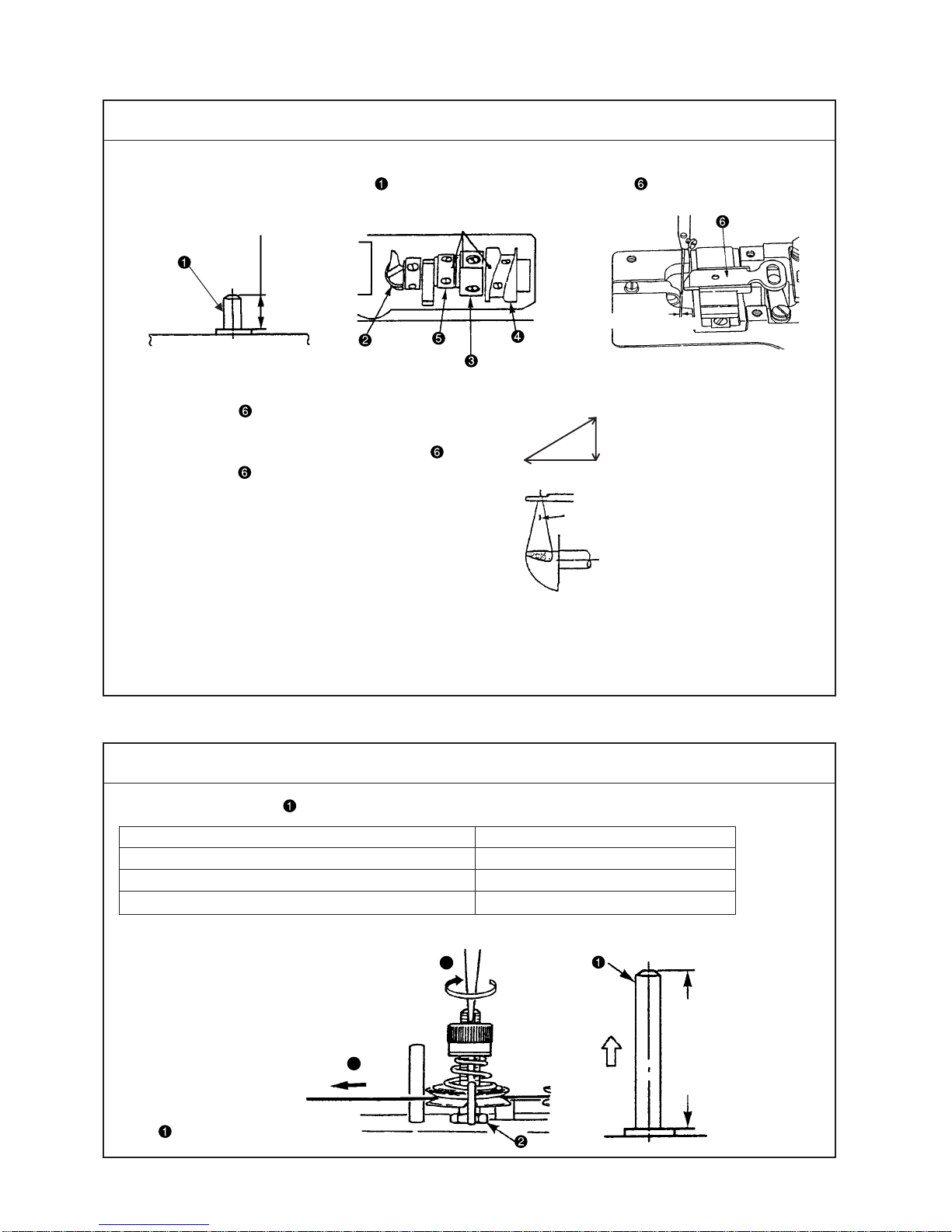
2. Adjust loop positioning finger cam as described below:
Yoke slide has to travel backward linearly along the oblique side
of its triangular movement. For adjustment, the cam should be turned
in the reverse direction of rotation if the yoke slide travels backward
non-linearly along a convex curve, or in the direction of rotation if it
travels along a concave curve.
3. Adjust the longitudinal position of the yoke slide by moving loop
positioning finger cam in the lengthwise direction.
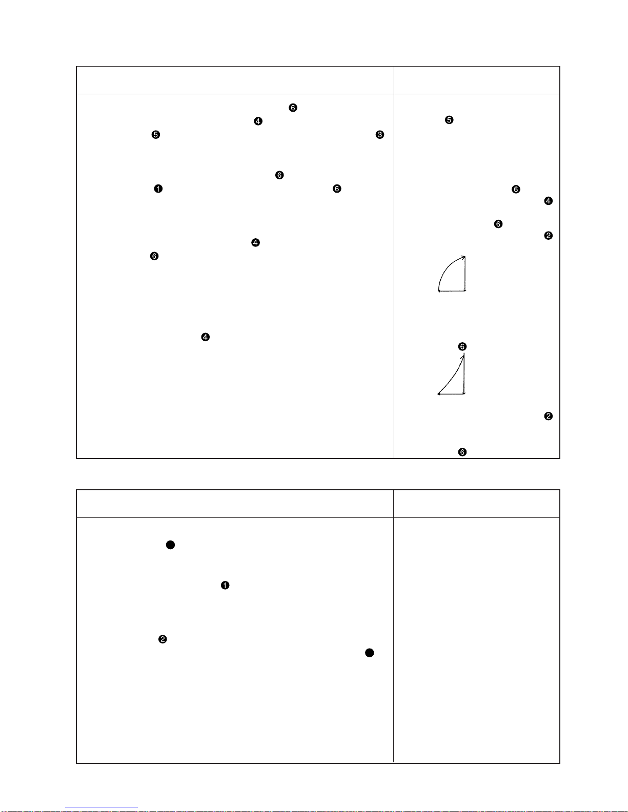
oIf loop positioning finger triangu-
lar cam begins to travel too late,
thread breakage, excess thread,
balloon stitches, and insufficient
tightness of the stitches will result.
Onthe contrary,if itbegins tomove
too early, the needle will come into
contact with yoke slide .
oIf loop positioning finger cam
begins to go back too early, the
retreat of yoke slide will become
like a swollen line and looper
will hook the thread twice.
oOn the other hand, if it begins to
retreat too late, its retreat will
become like a hollow line and the
needle will come into contact with
yoke slide .
oIf the longitudinal position of the
yoke slide is improper, looper
will hook the thread twice or the
needle will come into contact with
yoke slide .
1. Turn the needle driving pulley as you draw the thread in the direction
of arrow mark Aand you will find a point at which the tension disc
on the tension post No. 2 release the thread. At this moment, the
standard distance from the top end of the needle bar bushing (upper)
to the top end of needle bar is 44 to 47 mm (in case of the needle
of TQ x 7, 54 to 57 mm)
Perform the following adjustments especially when the
undermentioned troubles occur frequently.
2. Loosen nut , insert the blade of a screwdriver to the top slot of
the tension post No. 2 and turn it in the direction of arrow mark Bto
lowerthe height of the thread floating bar and in the opposite direction
to raise the height.
oIf the thread tension is released
too early, excess thread and/or
poor tightness of the stitches will
result.
oOn the other hand, if the timing of
the thread tension release is too
late, thread will break.
Yoke slide retreats
like a swollen line.
Yoke slide retreats
like a hollow line.
Adjustment Procedure Results of Improper Adjustment

– 6 –
(5) Height and pressure of the button clamp
(6)Thread tension disc No. 1
At the time of stop-motion
1mm
Standard Adjustment
Standard Adjustment
1. The amount of lift of the button clamp
A: 8.5 to 9.5 mm
2. Pressure of the button clamp
A
28.5 to 29.5mm

– 7 –
1. Amount of lift of the button clamp
(1) The knife moves in accordance with the lifting of the button
clamp. Therefore, the length of the remaining thread on the
wrong side of a fabric depends upon the height of the button
clamp at which the thread is trimmed.
(2) When the machine is in stop-motion status and when the stop-
motion hook comes in contact with the stop-motion disc,
standard clearance Abetween the back side of the bottom
face of button clamp jaw lever and the top face feed plate
is 8.5 to 9.5 mm.
(3) To adjust the height of the button clamp unit, loosen screw
in the button clamp lifting hook and move button clamp lifting
hook up or down.
2. Button clamp pressure
(1) The standard work pressure force is obtained when a clearance
of 28.5 to 29.5 mm is provided between the top end of nut
and the bottom end of pressure adjusting bar . Turn nut to
adjust the clearance to the aforementioned value.
oIncreasing the lifting amount of the
button clamp will increase the
length of the remaining thread.
oIf the height of the button clamp is
too low, the remaining length of the
thread will be shorter.
oIf the pressure of the button clamp
is too low, the thread end at the
start of sewing will come out on
the wrong side of the fabric
unevenly by 10 to 20 mm.
1. Adjust so that tension disc floats by 1 mm at the time of stop-
motion by moving thread tension releasing lever laterally.
2. If thread tension releasing lever is not correctly positioned, the
disc may remain floating during sewing.
oIf the floating amount is too high,
the thread tension disc keeps
floating during sewing operation,
resulting in insufficient button
stitching.
oIf the floating amount is too low,
the thread length at the start of
sewing will become short,
resulting in thread slip-off.
Adjustment Procedure Results of Improper Adjustment

– 8 –
(7)Positioning the thread nipper
The clearance between thread nipper and nipper block should be 0.4 to 0.6 mm while the machine is in
operation.
0.4 to 0.6mm
(8) Adjusting the stitch selecting mechanism
1. Open the side cover (left). Change the number of stitches with stitch adjusting screw and stitch adjusting
lever (accessory part).
(1) Adjusting the mechanism for 8 stitches (2) Adjusting the mechanism for 16 stitches
(3) Adjusting the mechanism for 32 stitches
Standard Adjustment
Standard Adjustment

– 9 –
1. Provide a 0.4 to 0.6 mm clearance between nipper block and
nipper to prevent nipper from holding the threading while the
machine is in operation.
2. To adjust the aforementioned clearance, loosen screw and move
nipper bar block to the right or left.
oIf the clearance is too large, the
thread from the needle will be-
come too short.
oIf the clearance is too small, some
types of thread will be broken.
(1) Adjusting the stitch selecting mechanism for 8 stitches
To set the number of stitches to eight, loosen stitch adjusting screw
to the position as illustrated. Then, tighten the screw.
(2) Adjusting the stitch selecting mechanism for 16 stitches
When the stitch adjusting screw is in the left side position with
the mechanism in the 8-stitch state, loosen stitch adjusting screw
to the position as illustrated. Then, tighten the screw.
(3) Adjusting the stitch selecting mechanism for 32 stitches
When stitch adjusting gear roller mounted on large gear is in
the lower position with the mechanism in the 16-stitch state, mount
stitch number lever (accessory part) using shoulder screw
(accessory part).
(Caution) Check to be sure that the stitch adjusting gear roller
mounted on gear (large) is positioned at the one-tooth
left side of the center of the needle driving pulley shaft
when the roller comes to the upper position with the
mechanism remained in the 16-stitch state.
Adjustment Procedure Results of Improper Adjustment

– 10 –
(9) Positioning the stitch adjusting cam
The clearance between stitch adjusting roller and the recess of stitch adjusting cam should be 0.8 mm at
the stop-motion position.
(10)Adjusting the stop-motion position
The state where stop-motion adjusting The state where stop-motion adjusting
cam is moved in direction A cam is moved in direction B
0.8mm
Rotational direction
of stitch adjusting
cam.
A
Stop-motion position
BA
Standard Adjustment
Standard Adjustment
Rotational direction
of stop-motion disc.

– 11 –
At the time of stop-motion of the machine, adjust so that a clearance of
0.8 mm is provided between stitch adjusting roller and the dent in
stitch adjusting cam when stop-motion hook comes in contact with
stop-motion disc and tighten setscrew A.
oIf the stop-motion impact is exces-
sive, adjust stop-motion adjusting
cam in direction A. If the ma-
chine stops before the stop-motion
position is reached, adjust cam
in direction B.
When the machine finishes sewing and stops, adjust it so that stop-
motion disc latch comes into contact with stop-motion hook .
(Caution) To change the number of revolutions from 1300 rpm to
1500 rpm by changing the motor pulley, be sure to re-
adjust the stop-motion position without exceptions.
1. If stop-motion hook hits against the stop-motion disc and bounces
back (i.e., when a gap is left between latch and stop-motion
hook ):
Loosen stop-motion position adjusting screws (one each at two
locations), and rotate stop-motion adjusting cam in direction A to
adjust it so that the stop-motion disc latch comes into contact with
the stop-motion hook. Then, tighten stop-motion position adjusting
screws .
2. If the stop-motion hook stops before the stop-motion disc latch is
reached:
Loosen stop-motion position adjusting screw (one each at two
locations), and rotate stop-motion adjusting cam in direction B to
adjust it so that the stop-motion latch comes into contact with the
stop-motion hook. Then, tighten stop-motion position adjusting
screws .
Adjustment Procedure Results of Improper Adjustment

– 12 –
A
(11)Positioning the stop-motion disc and the stop-motion hook
The clearance between stop-motion hook and stop-motion disc should be adjusted to 0.5 to 1mm at the
position which one stitch before the stop-motion position.
0.5 to 1mm
The clearance B between stop motion plunger lever and stop motion hook should be 8.5 mm.
Standard Adjustment
B
C
*Turn the cam to the position of the
previous stitch.

– 13 –
1. Turn stop-motion adjusting cam in direction A until it will go no
further.
See “(10) Adjusting the stop-motion position.”
2. Bring the machine at the position which is one-stitch before the stop-
motion position.
3. Remove driving pulley pressure applying lever .
4. Loosen screw in the stitch adjusting arm. In the state where stitch
adjusting roller comes in contact with portion Cof stop-motion
adjusting cam , adjust the clearance between stop-motion hook
and stop-motion disc to 0.5 to 1 mm. Then tighten setscrew
preventing a play, in the thrusting direction, in the stop-motion
shaft.
(Caution) Do not put the stitch adjusting roller in the recess of the
stitch adjusting cam.
5. Dimension B should be adjusted to 8.5 mm by means of adjusting
nut of the stop-motion spring.
oIf the clearance is larger than 0.5
to 1 mm, unstable entrance into
the stop-motion state will result.
oIf the clearance is smaller, the
stop-motion disc may come into
contact with the stop-motion hook
during operation.
oIf the clearance is larger than 8.5
mm, the shock noise of the stop-
motion will be high or stop-motion
hook will come off.
oIf the clearance is smaller, the
position of stop-motion disc will
become unstable at the time of
stop-motion.
Adjustment Procedure Results of Improper Adjustment

– 14 –
(12)Changing over the quick stitch-shape changing mechanism (MB-1377)
Adjusting the mechanism for 2-holed button sewing and for 4-holed button sewing
A
BC
A
Standard Adjustment

– 15 –
(Caution) Make sure that the machine is at the stop-motion
position (see 2.-(10)Adjusting the stop-motion position)
before carrying out the adjustment of the quick-change
mechanism.
1. Measure the space between holes in a button (in mm). In the case
of 4-holed buttons, the lengthwise feed amount and crosswise feed
amount should be set at the same scale on the graduated plate.
[For MB-1373]
★Lengthwise feed scale
For 2-holed buttons, while keeping lengthwise feed adjusting lever
pressed down, set the spring at "0" on the graduated plate. For 4-holed
buttons, the spring should be set as described below according to the
stitch shape to be employed:
★Crosswise feed scale
Loosen nut . Set portion Aof pointer to the scale corresponding
to the space between the measured holes. Then, tighten nut .
[For MB-1377]
★Lengthwise feed scale
For 2-holed buttons, while keeping lengthwise feed adjusting lever
pressed down, set the spring to "0" on the graduated plate. For 4-holed
buttons, the spring should be set as described below according to the
stitch shape to be employed:
X-shape stitching: Set the spring at the scale, within range A,
corresponding to the space between the measured
holes.
U-shape stitching: Set the spring at the scale, within range B,
corresponding to the space between the measured
holes.
(Caution) If the spring is set at scale position C (outside the setting
range of the scales), not only can sewing not be
performed, but sewing troubles can also occur. Never
set the feed adjusting lever at the position of scale C.
★Crosswise feed scale
Loosen nut . Set portion Aof pointer to the scale corresponding
to the space between the measured holes. Then, tighten nut .
(Caution) Check to be sure that the needle enters exactly the
center of each hole in the button before operating the
machine.
Adjustment Procedure Results of Improper Adjustment

– 16 –
(13) Positioning the feed cam
Align the engraved dot on the periphery of the feed cam (lengthwise feed cam , crosswise feed cam ) with
pointer fixed on the bed at the time of stop-motion when performing sewing of buttons with 16 stitches.
(14)Positioning the button clamp lifting link
Adjust so that the end face of lifting link is aligned with that of button clamp hook at the time of stop-
motion.
Standard Adjustment
Standard Adjustment
Engraved line
Aligned
Other manuals for MB-1373
3
This manual suits for next models
1
Table of contents
Other JUKI Sewing Machine manuals

JUKI
JUKI PLC-2700 Series User manual

JUKI
JUKI MEB-3200C User manual

JUKI
JUKI HZL-F series User manual

JUKI
JUKI HZL-E71 User manual

JUKI
JUKI LU-562 User manual

JUKI
JUKI PLC-1710-7 User manual

JUKI
JUKI MB-372 User manual

JUKI
JUKI DDL-8700 User manual

JUKI
JUKI UnionSpecial 35800DLU Setup guide

JUKI
JUKI LK-1910 User manual

JUKI
JUKI LZ-2290A Series User manual

JUKI
JUKI AMS-210E/IP-410 User manual

JUKI
JUKI DDL-5550N User manual

JUKI
JUKI MB-1800B User manual

JUKI
JUKI MF-7000 Series Quick start guide

JUKI
JUKI DDL-5550-7 User manual

JUKI
JUKI DLU-5490N User manual

JUKI
JUKI LH-4128 User manual

JUKI
JUKI MO-6000 Series User manual

JUKI
JUKI MS-1190 User manual