JUKI MO-6904S User manual

ASN-690
INSTRUCTION MANUAL

i
CONTENTS
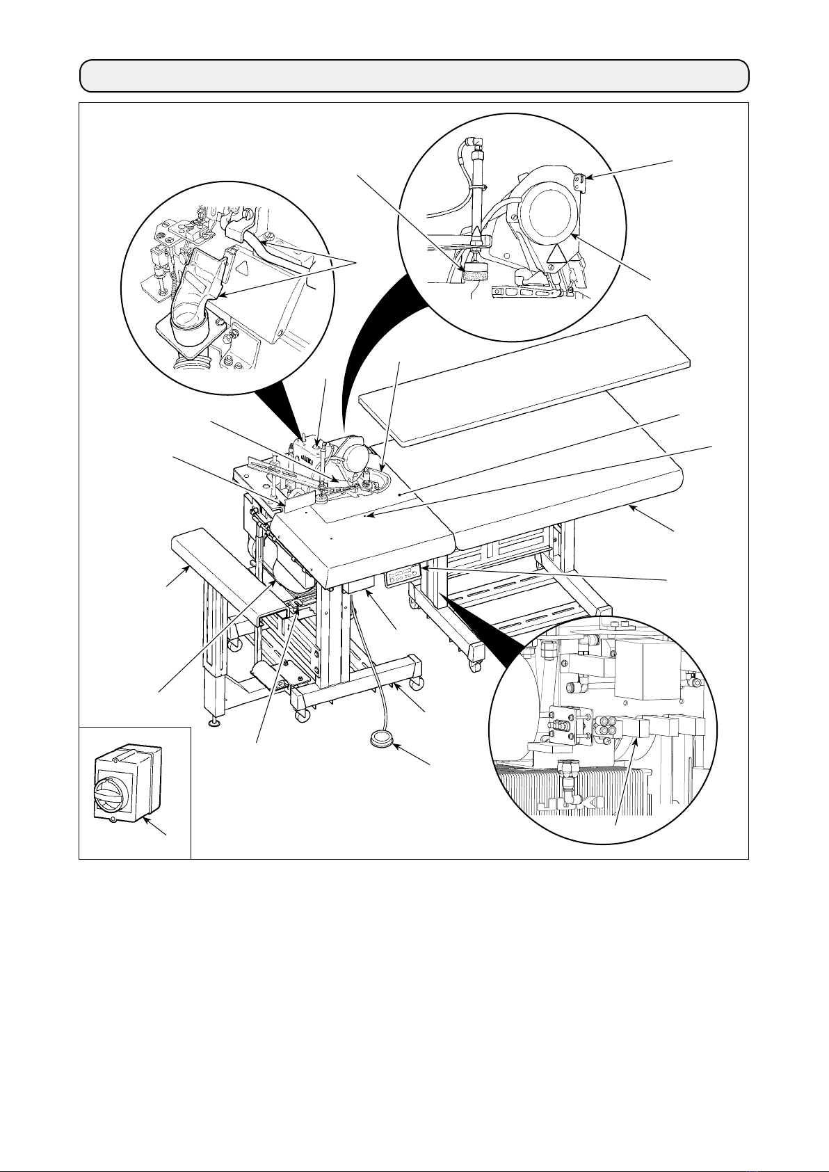
1. CONFIGURATION OF THE MACHINE ...................................................... 1
2. SPECIFICATIONS....................................................................................... 2
3. INSTALLATION........................................................................................... 3
3-1. Removing packing materials ............................................................................................................3
3-2. Securing the machine........................................................................................................................ 3
3-3. Installing the dust collector ..............................................................................................................4
3-4. Installing the stacker .........................................................................................................................5
3-5. Installing the stacker cloth guide .....................................................................................................6
3-6. Installing the cloth plate and the cloth guide unit ..........................................................................7
3-7. Installing the thread stand ................................................................................................................8
3-8. Installing the regulator ......................................................................................................................8
3-9. Connecting the air coupler................................................................................................................ 9
3-10. Connecting the starting pedal for the machine............................................................................. 9
3-11. Joining the sub-table (only for the long table type).................................................................... 10
3-12. Connecting the power plug........................................................................................................... 12
3-13. Installing the cloth receiving board (KM-5) (optional) ................................................................13
3-14. Installing the 3-pedal unit (PK-79) (optional)...............................................................................14
4. PREPARATION......................................................................................... 15
4-1. Caution before operation ................................................................................................................15
4-2. Lubrication........................................................................................................................................ 15
4-3. Threading the machine.................................................................................................................... 16
4-4. Adjusting the pressure of the presser foot and removing the presser foot............................... 17
4-5. Adjusting the stitch length..............................................................................................................17
4-6. Differential feed mechanism ...........................................................................................................18
5. OPERATION ............................................................................................. 19
5-1. Sewing procedure ............................................................................................................................19
5-2. Explanation of the operation panel ................................................................................................22
5-3. Description of the pedals and the switches on the machine head ............................................. 23
5-4. List of functions to be set ...............................................................................................................24
5-5. Details of selected functions ..........................................................................................................25
5-6. Other settings................................................................................................................................... 28
5-7. Initialization of the setting data ......................................................................................................28
6. ADJUSTMENT .......................................................................................... 29
6-1. Stacker support board adjustment................................................................................................. 29
6-2. Adjusting the position of the thread trimmer presser ..................................................................30
6-3. Adjusting the air blow......................................................................................................................30
6-4. Adjusting the edge guide ................................................................................................................31
6-5. Adjusting the cloth guide ................................................................................................................32
6-6. Regulator adjustment ......................................................................................................................32
6-7. Adjusting the cloth chip suction force...........................................................................................33
6-8. Adjusting the sensors......................................................................................................................34

ii
7. MAINTENANCE........................................................................................ 37
7-1. Adjusting the knife...........................................................................................................................37
7-2. Cleaning the machine head............................................................................................................. 37
7-3. Checking the cartridge lter and replacing it................................................................................ 38
7-4. Changing the machine oil ...............................................................................................................38
7-5. Changing needles ............................................................................................................................39
7-6. Drainage of lter regulator ..............................................................................................................39
7-7. Cautions for the compressed air supply (source of supply air) facility ..................................... 40
7-8. Dust collector box............................................................................................................................ 41
7-9. Cleaning the sensor......................................................................................................................... 41
7-10. Consumable parts to be replaced ................................................................................................42
7-11. Replacing the fuse .........................................................................................................................43
7-12. Adjusting the belt tension .............................................................................................................44
7-13. Destination of connection for input/output connectors.............................................................45
7-14. Error codes .....................................................................................................................................46
7-15. Error code list................................................................................................................................. 47

– 1 –
1.CONFIGURATIONOFTHEMACHINE
AMain body structural mechanism section
(table stand, machine support and sewing table
covers)
BStacker unit
CSub-table
DCloth plate
ESewing machine head
FCloth guide
GControl box
HSewing machine motor
IStart switch for the stacker
JStacker cloth guide
KSide cutter
LDust collector
MPneumatic controller
NPower switch
OStarting pedal for the sewing machine
PThread trimmer presser
QCloth feeding air blow
RPause switch
SOperation panel CP-18
TPower switch (EU type)
(also used as the emergency stop switch)
A
B
C
D
O
G
N
Q
H
J
K
M
L
F
I
R
P
E
S
T

– 2 –
2.SPECIFICATIONS
1 Machine head MO-6904S 1-needle overlock machine
2 Sewing speed Max. 8,000 sti/min *1
3 Stitch system JIS E13 (USA standard : 504)
4 Stitch length 0.8 to 4 mm
5 Overedging width 4.0 mm (E), 4.8 mm (F), 5.6 mm (G)
6 Needle ORGAN DC x 27 #9 to #14 (Standard : #11)
7 Thread Spun thread #60 (recommended)
8 Chain-off thread
cutter
Pneumatic side cutter
9 Presser foot lift Max. 7 mm (for the machine provided with AK-139)
10 Differential feed
ratio
Gathering 1 : 2 (max. 1 : 4), stretching 1 : 0.7 (max. 1 : 0.6)
11 Sewing specica-
tions
A Cutting curve
B Material size
C Number of plies of material
... In-curve R200 or more
... Out-curve R300 or more
... 400 mm or less (width), 650 mm or more (length)
… Limited to one
12 Number of piec-
es that can be
stacked
70 (slacks)
13 Power consump-
tion
420VA or less (operating rate 50 %)
14 Pneumatic pres-
sure
0.5MPa
15 Air consumption 250dm3/min(ANR)
16 Lubricating oil JUKI MACHINE OIL 18
17 Dimensions Type Width Length Height
Short table type 790 mm 575 mm
(875 mm *2 )
880 mm
Long table type 1500 mm
(1800 mm *2 )
790 mm 880 mm
18 Mass of the ma-
chine
Short table type : 110 kg
Long table type : 160 kg
19 Noise - Equivalent continuous emission sound pressure level (LpA) at the workstation :
A-weighted value of 90.5 dB; (Includes KpA = 2.5 dB); according to ISO 10821- C.6.3
-ISO 11204 GR2 at 8,000 sti/min.
- Sound power level (LWA) ;
A-weighted value of 94.0 dB; (Includes KWA = 2.5 dB); according to ISO 10821- C.6.3
-ISO 3744 GR2 at 8,000 sti/min.
*1 "sti/min"isanabbreviationfor"stitchesperminute."
*2 Machinedimensionsincludingthestacker

– 3 –
3.INSTALLATION
3-1.Removingpackingmaterials
Removethestringwhichsecures
the power cable.
Remove the tape which secures
the cloth plate.
Removethestringwhichsecures
the hose.
3-2.Securingthemachine
CAUTION :
Toavoidpossiblepersonalinjuries,besuretomovethemachinetoalevelandstableplaceandlock
casters ❶.
❶

– 4 –
3-3.Installingthedustcollector
1) Plug the lings blowing hose ❷and the chain-
off thread blowing hose ❸into the dust collec-
tion box ❶.
2) Install lter ❹so that it completely covers the
top of the box.
Install the dust collection box ❶to the rear of the
main unit, as shown in the gure.
(Conguration position differs depending upon speci-
cation.)
Shorttabletype
Longtabletype
Whendumpingdustfromthedustcollec-
tionbox,alsocleanuplter❹.
Conrmthatthehosemountingbracket❺
iscompletelytightened(thesameforother
mountinghardware).Notethatthenoise
mufer❻is optional.
CAUTION :
If the dust collector is not securely in-
stalled,blown-outdustorlintcangetin
eyes,resultinginpersonalinjury.
❶
❷
❸
❹
❺
❶
❺
❻

– 5 –
3-4.Installingthestacker
1) Install the stacker unit on the base with screws
❶and washers ❷(at two locations each).
2) Adjust adjusting bolt ❸to make the support rod
of the stacker parallel to the installing plane.
3) Connect air tube ❹to joint ❺and air tube ❻to
joint ❼in numerical order.
CAUTION :
Besuretocarryoutinstallationofthestackerbytwoormoreworkersinordertoprotectagainst
accidentscausedbythestackerunitwhenitaccidentallyfalls.
❶❷
❸
❼
❺
❻
❹

– 6 –
❶
❸
❷
❹
❶
3-5.Installingthestackerclothguide
Installing stacker cloth guide ❶on the guide base
with hand screw ❷and washer ❸.
Adjust the orientation of the cloth guide according to
the clamping position at the stacker unit ❹.
Materialfeedingdirection

– 7 –
3-6.Installingtheclothplateandtheclothguideunit
1) Place the cloth plate on the sewing machine
table.
2) Put the slots (at two locations) in the cloth guide
unit as illustrated in the gure over two studs ❶
(at two locations) of the cloth plate over. Fix the
studs ❶with washer ❸and thumb screws ❷.
3) Connect air tube ❹to joint ❺.
Installingposition
Cloth plate
Clothguideunit
❶
❺
❹
❷
❷
❸
❸

– 8 –
❶
3-7.Installingthethreadstand
Insert the thread stand into the hole in table ❶with
a washer placed between them and x with the nut
and washers from under the table as illustrated in
the gure at left.
Washer
Washer
Springwasher
Nut
3-8.Installingtheregulator
Fix regulator ❶on mounting plate ❷with screws ❸
(at two locations).
Connect ø8 air tube ❹to joint ❺.
❷
❶
❸
❹
❺

– 9 –
3-10.Connectingthestartingpedalforthemachine
Connector ❷of starting pedal ❶to junction connec-
tor ❹coming from control box ❸.
3-9.Connectingtheaircoupler
Connect the air coupler ❶supplied with the unit as
an accessory rstly to air hose ❷, secondly to cou-
pler ❸on the main body side.
Makesurethatthepressuregaugeofthe
regulatorreads0.5MPa.
❷❶❸
❹
❶
❷
❸

– 10 –
❶
❸
❷
❹
3-11.Joiningthesub-table(onlyforthelongtabletype)
Butting the sub-table and the main-body table with no clearance provided between them, x clips ❶(at three
locations) with thumbscrews ❷. Lock casters ❸(at four locations) to secure the sub-table.
Sub-table
Main-bodytable
CAUTION :
Connectthesub-tabletothemain-bodytabletakingcarenottoallowyourngerscaughtbetween
them.
A difference in height between the top face of the main-body table and that of the sub-table may be observed
on some installation site.
If such a difference is observed, adjust so that the tables are same in height with spacers ❹for adjusting the
height of the clips. (Three spacers are supplied.)
・
If the sub-table is lower than the main-body table :
Add the supplied spacer(s) appropriately.
・
If the sub-table is higher than the main-body table :
Remove spacer ❹and change with a thinner one.

– 11 –
❺
❻
❻
❺
To adjust the height of the main-body table, loosen screws ❺that secure the casters (at six locations) to
adjust the height of the main-body table to that of the sub-table and tighten the screws ❺.
To adjust the height of the sub-table, loosen screws ❻that secure the casters (at six locations) to adjust the
height of the sub-table to that of the main-body table and tighten the screws ❻.
Sub-table
Main-bodytable
If the difference in height between the sub-table and the main-body table cannot be eliminated with spacer ❹,
adjust the height of the main-body table (or the height of the sub-table).
CAUTION :
Toprotectagainstpossiblepersonalinjuryordeath,besuretoconnectthetableswhilesupporting
themachinebyfourormoreworkers.

– 12 –
Connection of the power plug to the power depends on the specications of the product. Adjust the power
plug to the power specications to connect.
3-12.Connectingthepowerplug
① Incaseoftheproductofsingle-phase,200to240Vspecications(CEspecications):
Connect the sky-blue and brown wires of the power cord to the power terminal (AC200 to 240V) and the
yellow/green wire to the ground (earth) terminal respectively.
③ Incaseoftheproductof3-phase,200to240Vspecications:
Connect the red, white and black wires of the power cord to the power terminal (AC200 to 240V) and the
yellow/green wire to the ground (earth) terminal respectively.
② Incaseoftheproductofsingle-phase,200to240Vspecications(otherthanCEspecications):
Connect the black and white wires of the power cord to the power terminal (AC 200 to 240V), and the
yellow/green wire to the ground (earth) terminal respectively.
CAUTION :
Topreventpossibleaccidentscausedbyleakageordielectricstrength,anappropriatepowerplug
shallbeinstalledbyapersonwhohasanexpertknowledgeofelectricity.Besuretoconnectthe
powerplugtothereceptaclethatiswellgrounded.

– 13 –
3-13.Installingtheclothreceivingboard(KM-5)(optional)
1) Fix support rods ❷on cloth holding table ❶with wood screws ❸and washers ❹(at four locations
each).
2) Fix the cloth holding table mounted with the support rods on the sub-table with screws ❺.
Theclothholdingtablecanbeadjustedtofourdifferentheightsusingthexingholesinthesupport
rod.
❶
❸
❷
❹
❺
❺

– 14 –
3-14. Installing the 3-pedal unit (PK-79) (optional)
Connect the connector of the pedal to the junction
connector coming from the control box.
The gure shows differential feed switch ❶, pause
switch ❷ and high-/low-speed changeover switch ❸
from left to right.
❶Differential feed
switch
As long as this switch is held depressed, the differential feed function works.
❷Pause switch As long as this switch is held depressed, the pause function works. The machine returns
to the normal operation (running) by releasing the switch.
❸High-/low-speed
changeover switch
Changeover from the high-speed to low-speed can be done only by a depress on this
switch.
The machine returns to the normal operation (running) by releasing the switch.
❶ ❷ ❸

– 15 –
4. PREPARATION
4-1.Cautionbeforeoperation
1) Remove oil cap ❶.
2) Pour JUKI MACHINE OIL 18 into the oil reser-
voir.
3) Supply oil until the pointer bar almost reaches
the upper red marker line when oil gauge ❷is
observed from the side.
Iftheoilamountpointerbarexceedsthe
redmarkerline,theoilquantitybecomes
excessiveresultinginoilleakage.Besure
tostopaddingtheoilbeforetheredmark-
er line is reached.
❶
❷❷
4-2.Lubrication
CAUTION :
Toprotectagainstpossiblepersonalinjuryduetoabruptstartofthemachine,besuretostartthe
followingworkafterturningthepoweroffandascertainingthatthemotorisatrest.
• Before you put the machine into operation for the rst time, be sure to thoroughly clean it.
• Check to be sure that the voltage has been correctly set.
• Make sure that the power plug is connected properly.
• Never use the machine under a voltage that is different from the specication.
• Lubrication to chain-off thread trimming device
Remove screw ❶from the top end of the oil
hose at the rear section of the machine. The
upper limit of the oil quantity is at the top of the
pipe holder.
Oil consumption differs depending on the condi-
tion of use. The oil quantity should be checked
on a daily basis.
As a guide, lubricate the chain-off thread trim-
mer at the following intervals :
· Once a day for the continuous use
· Normally once every three to four days
Lubricant inlet
Pipe holder
Cloth plate side cover
Knifeplate(asm.)
Thechain-offthreadtrimmerhasnotbeen
factory-oiledatthetimeofdelivery.
JUKIMACHINEOIL18shouldbeusedfor
lubrication.
CAUTION :
Toavoidpossiblemalfunctionsanddamageofthemachine,checkthefollowingitems.
❶

– 16 –
To thread the machine head, remove the cloth plate
in advance.
4-3.Threadingthemachine
Whenusinganuntwistedthreadsuchas
woolynylonthreadorweakthread,do
not wind it round the intermediate thread
guide.
★ Howtoremovetheclothplate
Remove the cloth plate by holding the cloth plate
guide base.
Donottouchthecurvesensor(optional)
mounted on the cloth plate.
★ Howtothreadtheneedlethreadsiliconoil
tank
When the needle cooler is used. Pass the thread
under the center pawl.
When the needle cooler is not used. Pass the thread
above the center pawl.

– 17 –
1) Adjust the pressure of the presser foot by loos-
ening rst nut ❹and turning presser foot adjust
screw ❶.
When the adjust screw is turned clockwise, the
pressure will increase. When it is turned coun-
terclockwise, the pressure will decrease.
After the adjustment, be sure to turn nut ❹with-
out fail.
2) To open presser foot ❷sidewayd, raise the nee-
dle to the highest position of its stroke and lower
presser bar lifting lever ❸.
1) Slowly turn the handwheel as you keep depress-
ing pushbutton ❶, and you will nd a point at
which the pushbutton goes in farther.
2) With the above condition maintained, align the
desired scale mark on the handwheel with mark
❷on the belt cover.
3) Reset the pushbutton ❶after setting the dial.
4-5.Adjustingthestitchlength
CAUTION :
Toprotectagainstpossiblepersonalinjuryduetoabruptstartofthemachine,besuretostartthe
followingworkafterturningthepoweroffandascertainingthatthemotorisatrest.
To carry out adjustment, remove the cloth
plate in advance.
4-4.Adjustingthepressureofthepresserfootandremovingthepresserfoot
❶
❷
❹
❸
❶
❷
Table of contents
Other JUKI Sewing Machine manuals

JUKI
JUKI MO-50e User manual

JUKI
JUKI MO-654DE/654 User manual

JUKI
JUKI MH-481 User manual

JUKI
JUKI ASN-690 User manual

JUKI
JUKI M-1 Series User manual

JUKI
JUKI MO-734DE User manual

JUKI
JUKI DX-4000QVP User manual

JUKI
JUKI HZL-F series User manual

JUKI
JUKI HZL-F series User manual

JUKI
JUKI HZL35Z-UL5 User manual

JUKI
JUKI LS-341N User manual

JUKI
JUKI LK-1900A Quick start guide

JUKI
JUKI MO-804 User manual

JUKI
JUKI MO-735 User manual

JUKI
JUKI MO-6704DA User manual

JUKI
JUKI HZL-G Series User manual

JUKI
JUKI DNU-1541-7 User manual

JUKI
JUKI AMS-210E Series Quick start guide

JUKI
JUKI LU-2828V-7 User manual

JUKI
JUKI LBH-1790A Series User manual