CONTENTS
pa??=
.............................
1.
HOWTOSETUFTHEMACHINE
1
1)
How to install the oil reservoir
.............................
1
...............................
2)
Motor pulley and the belt
1
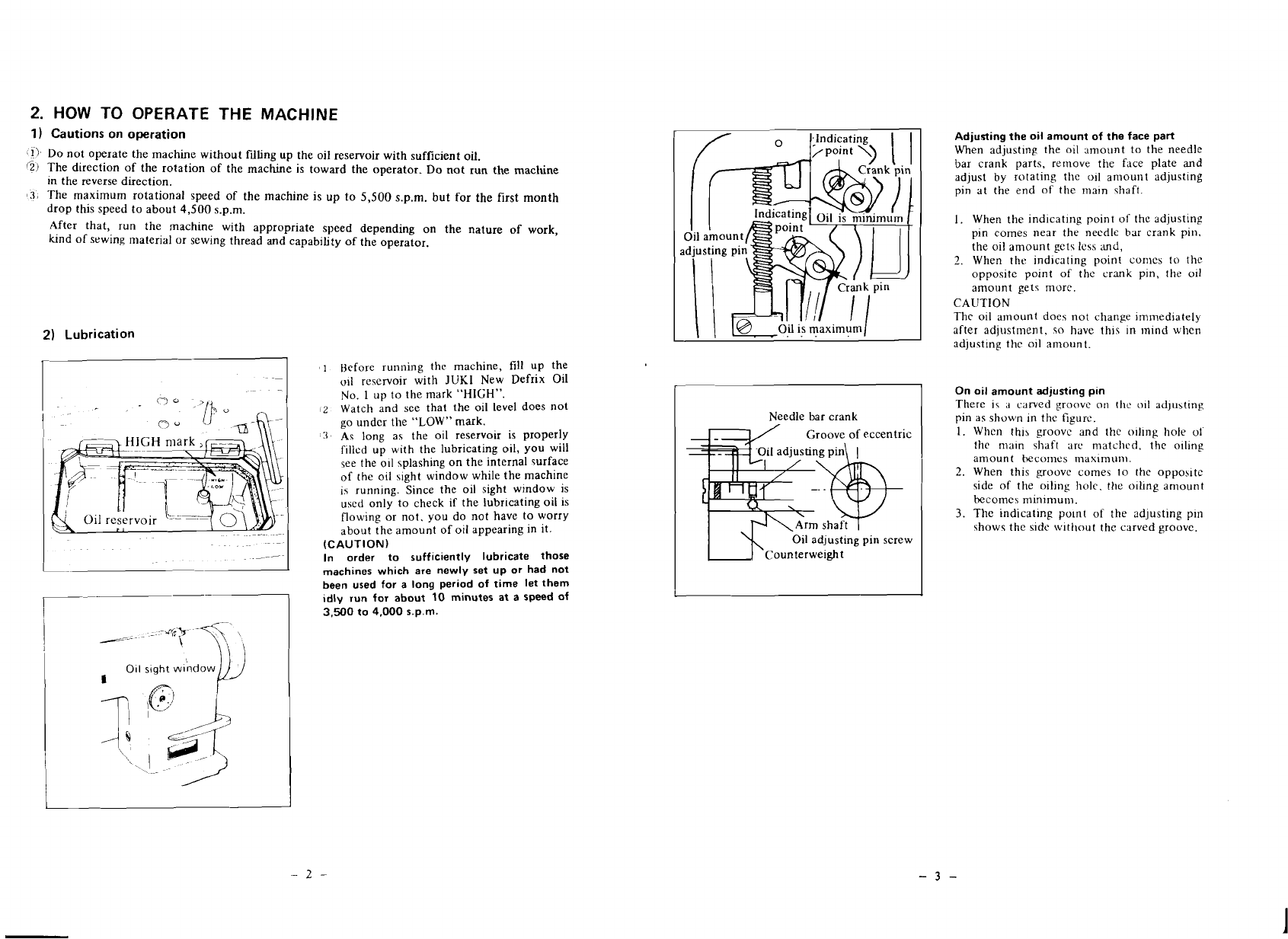
2.
HOW TO OPERATE THE MACHINE
...........................
2
-
...................................
1) Cautions on operation 2
2)
Lubrication
.........................................
2
Adjusting the oil amount of the face part
.....................
3
On oil amount adjusting pin
...............................
3
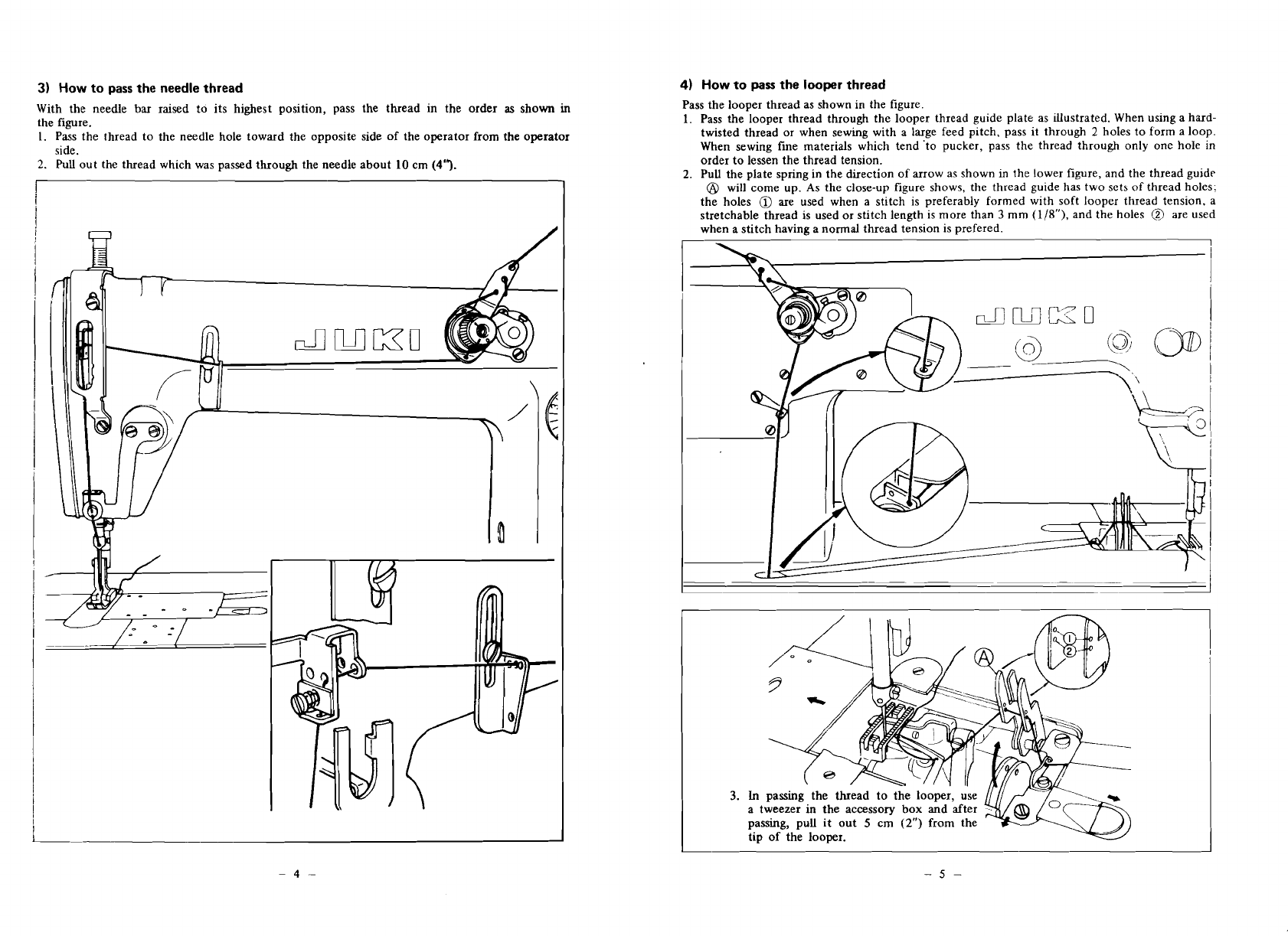
3) How to pass the needle thread
.............................
4
4) How to pass the looper thread
.............................
5
....................................
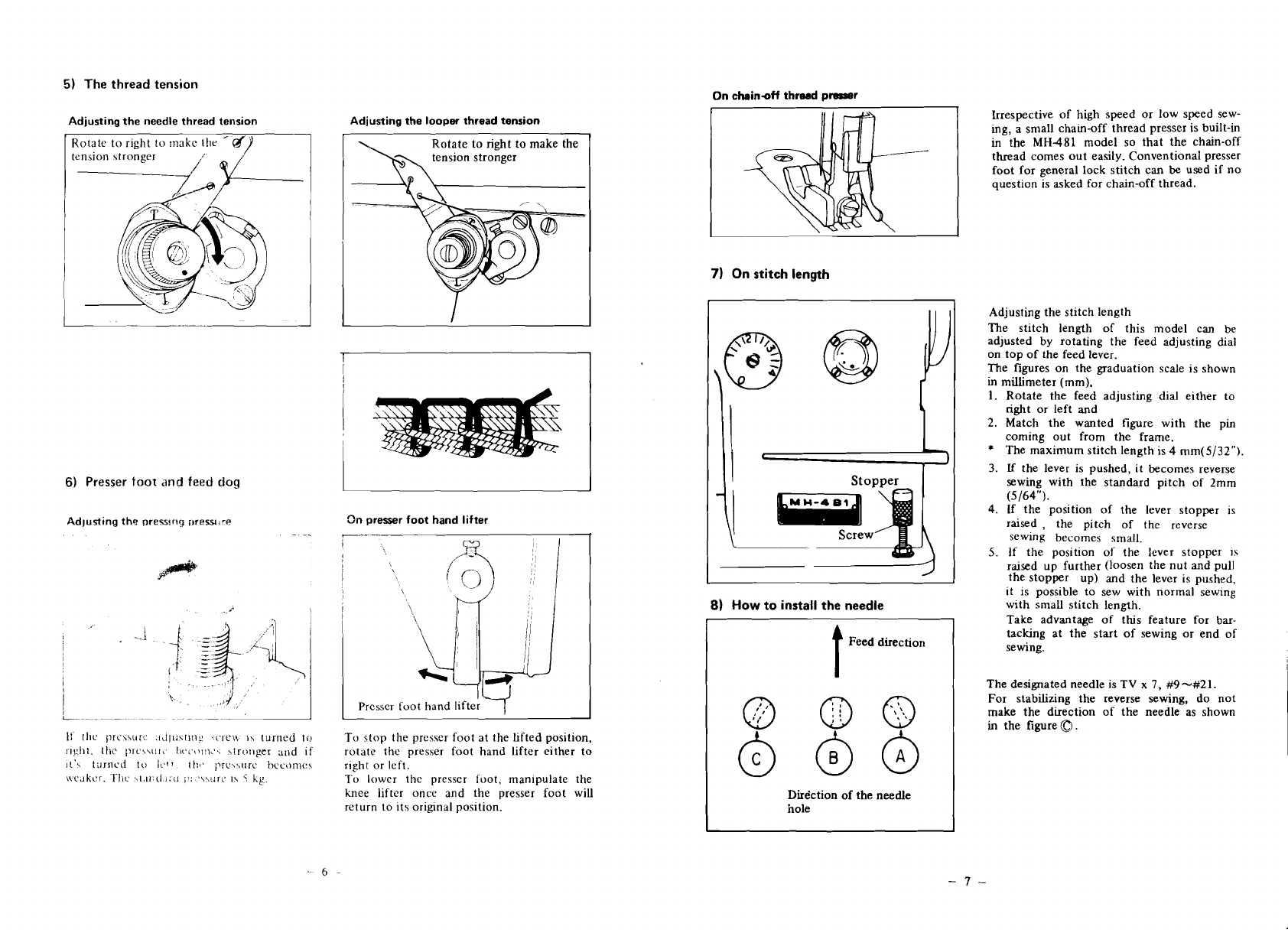
5) The thread tension.
6
.........................
Adjusting the needle thread tension
6
.........................
Adjusting the looper thread tension
6
...............................
6) Presser foot and feed dog
6
Adjusting the pressing pressure
.............................
6
................................
On presser foot hand lifter
6
On chain-off thread presser
...............................
7
7)
On stitch length
.....................................
7
...............................
Adjusting the stitch length
I
8)
How to install the needle.
................................
7
9)
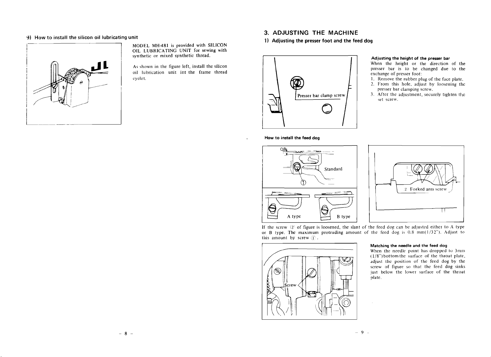
How to install the silicon oil lubricant unit
.....................
8
3. ADJUSTING THE MACHINE
...............................
9
.....................
1) Adjusting the presser foot and the feed dog 9
Adjusting the height of the presser bar
.......................
9
How to install the feed dog (MH-481)
........................
9
Matching the needle and the feed dog
.........................
9
..................
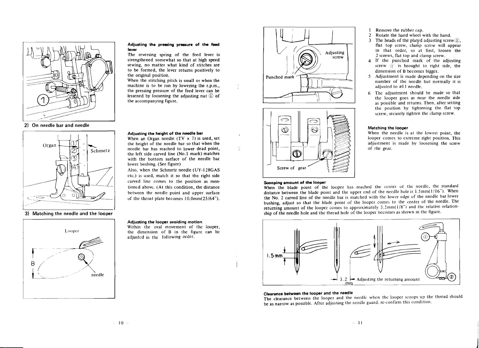
Adjusting the pressing pressure of the feed lever. 10
................................
2)
On needle bar and needle. 10
Adjusting the height of the needle bar.
........................
10
-
-
3) Matching the needle and the looper
.........................
10
Adjusting the looper avoiding motion
.........................
10
Matching the looper
...................................
11
Scoopingamount of the looper
..............................
Clearance between the looper and the needle. 11
....................
11
4)
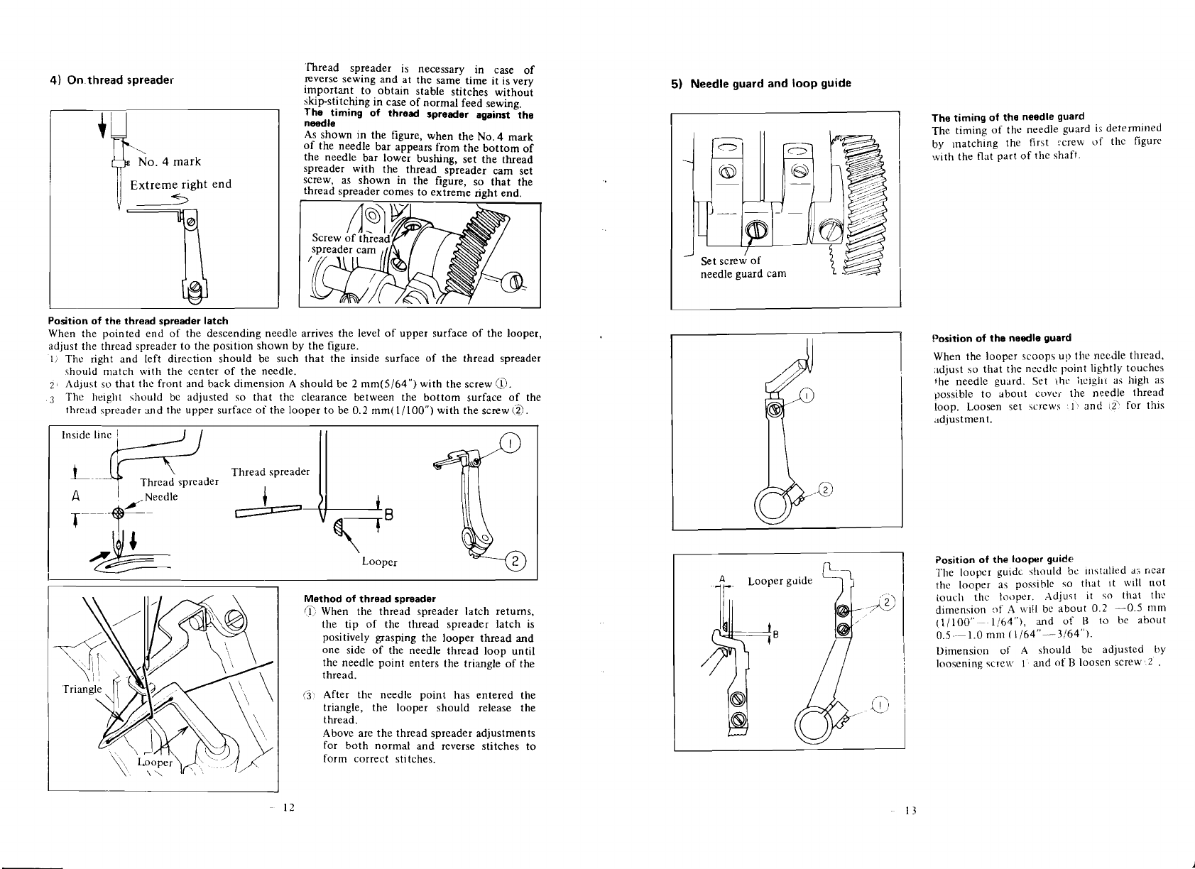
Onthreadspreader
.....................................
12
The timing of thread spreader against the needle
.................
12
Position of the thread spreader latch
.........................
12
Method of threhd spreader
...............................
12
5)
Needle guard and loop guide.
..............................
The timing of the needle guard 13
.............................
12
A"
...............................
Position of the needle guard 13
...............................
Position of the looper guide 13
...................................
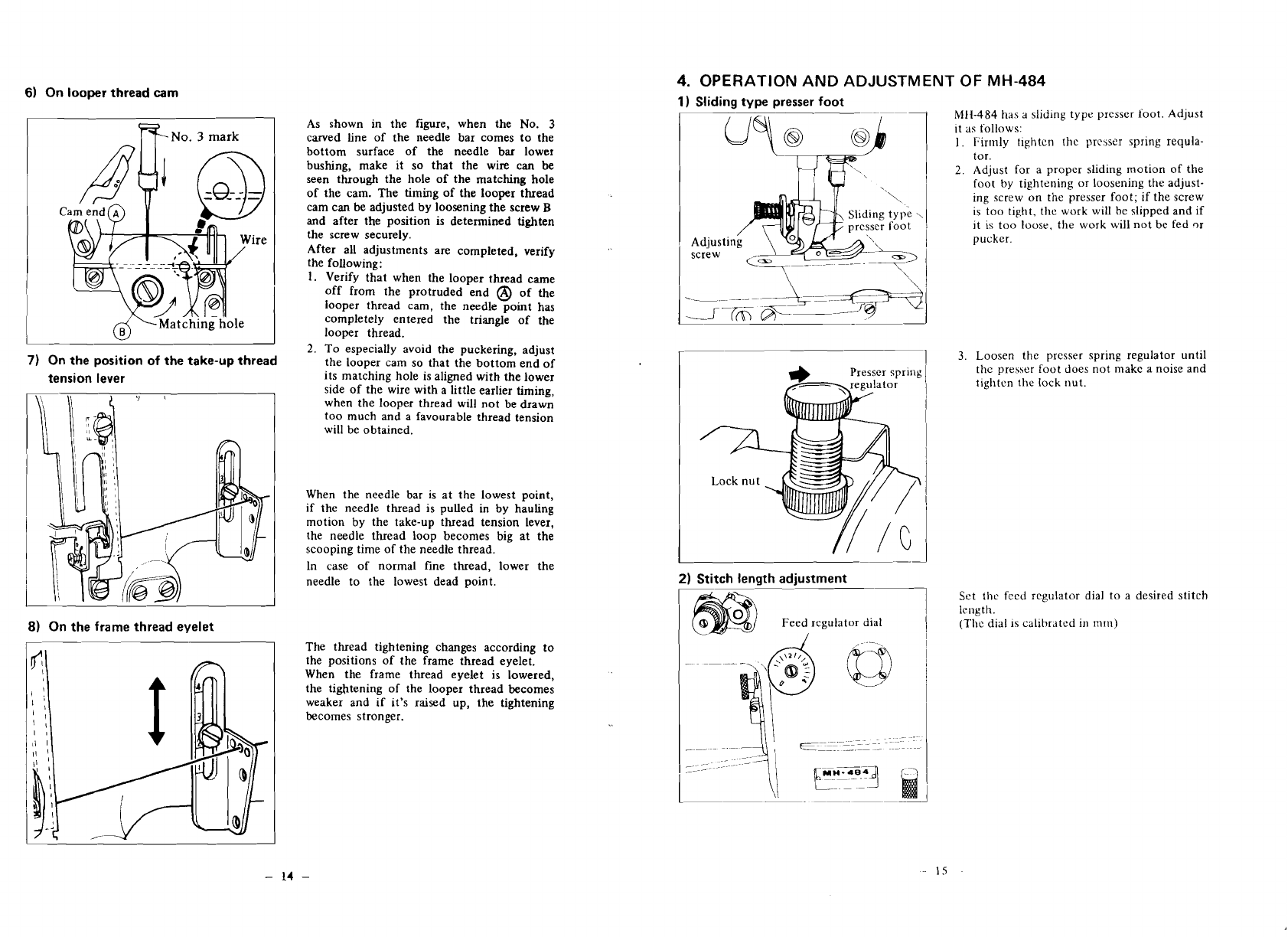
6)
On looper thread cam I4
7)
On the position of the take-up thread tension lever.
................
14
8)
011
the frame thread eyelet
...............................
14
4.
OPERATION AND ADJUSTMENT OFMH-484
.....................
15
5. b1AINTI:NANCE OFTIIE MACHINE
...........................
19
6.
MALI'UNCTIONS
AN[)
CORRECTIVE MEASURES
..................
19
1.
HOW
TO
SET
UP
THE
MACHINE
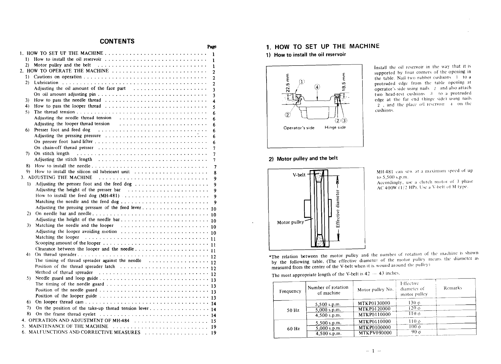
1)
How to install the oil reservoir
Operator's s~de
Hinge
side
Install the oil rcwrvolr In
thc
\lay that ~t
I5
supported by lour cornrrs
of
the opening In
the table. Nail t\\.o rut~hrrrurhion\
1
to
a
protruded edgc from thc tahle opening at
operator'\ cidc using nail?
2
and alw attach
two head-rest cu\h~on\
.(
to
3
protrudeii
edge at thc far cnd Ihingc crdc) Uclng nail5
2
,
and thc placv
i11l
rc\crvolr
.1
on thc
cuthion.;.
Il
2)
Motor pulley
and
the belt
Mil-481
can
\c\\
at
a
~ii,i\i~iiiin~'PCCJ
111
llp
to
5,500
\.p.n\.
Accordingly, uw
;I
clutch rliotor
ol
3
phahc
A('
400W
(1
'7
ill').
\<c
:I
\'-l)t-lt
01
X1
typc.
*The relation between the lllotor pulley and the number
ui
!-ot;~tlun
of
111~'
r~ldchlnc
IS
\h~\\'ll
by the following table. (The effective diameter
of
the motor pullc\ I1lr;rI1\ tllc Jiarnetcr aS
measured from the center of the V-belt when ~tis wourld around th?,pullc).)
The most appropriate length of the V-belt
IS
41
--
43
incllc\.
..
-p~
j
1~t'sci.rlv~
1
'
d~anlctci
oi
Kcrl~arkh
.
I
not0
I
'i