JUKI MF-7500 Series User manual

i
ENGLISH
INSTRUCTION MANUAL
MF-7500

i
CONTENTS
Ⅰ. SPECIFICATIONS .........................................................................................................1
Ⅱ. CONFIGURATION OF THE MACHINE COMPONENTS ..............................................2
Ⅲ.
INSTALLATION......................................................................................................................3
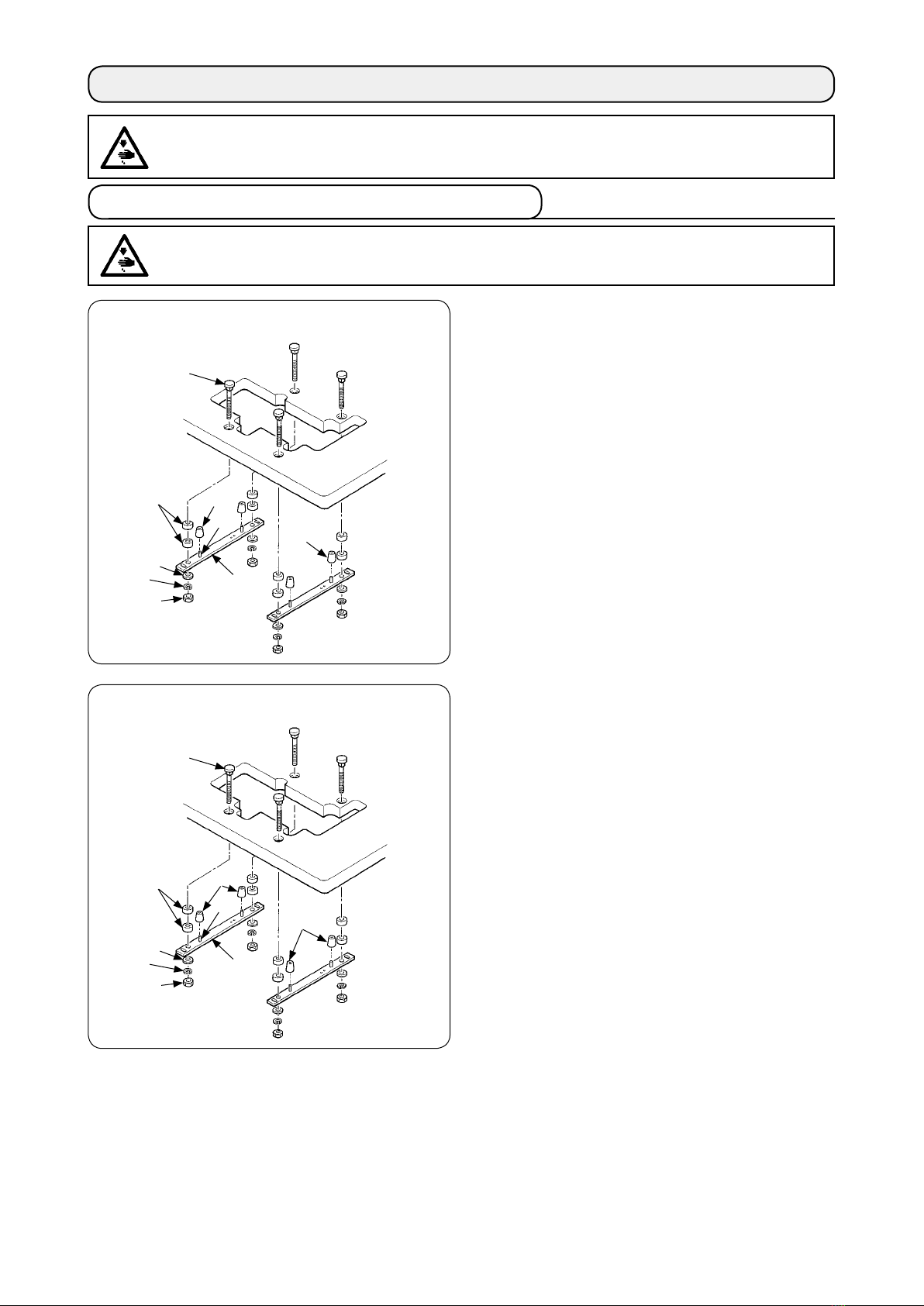
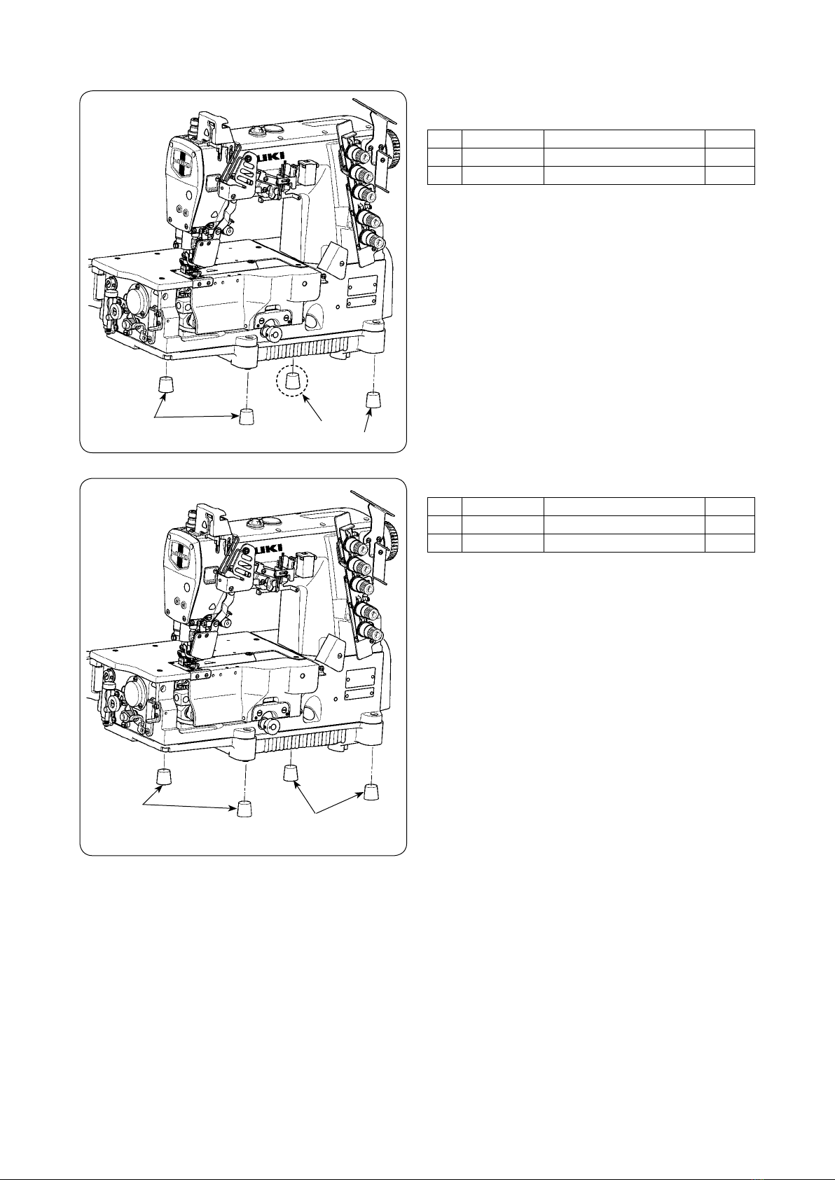
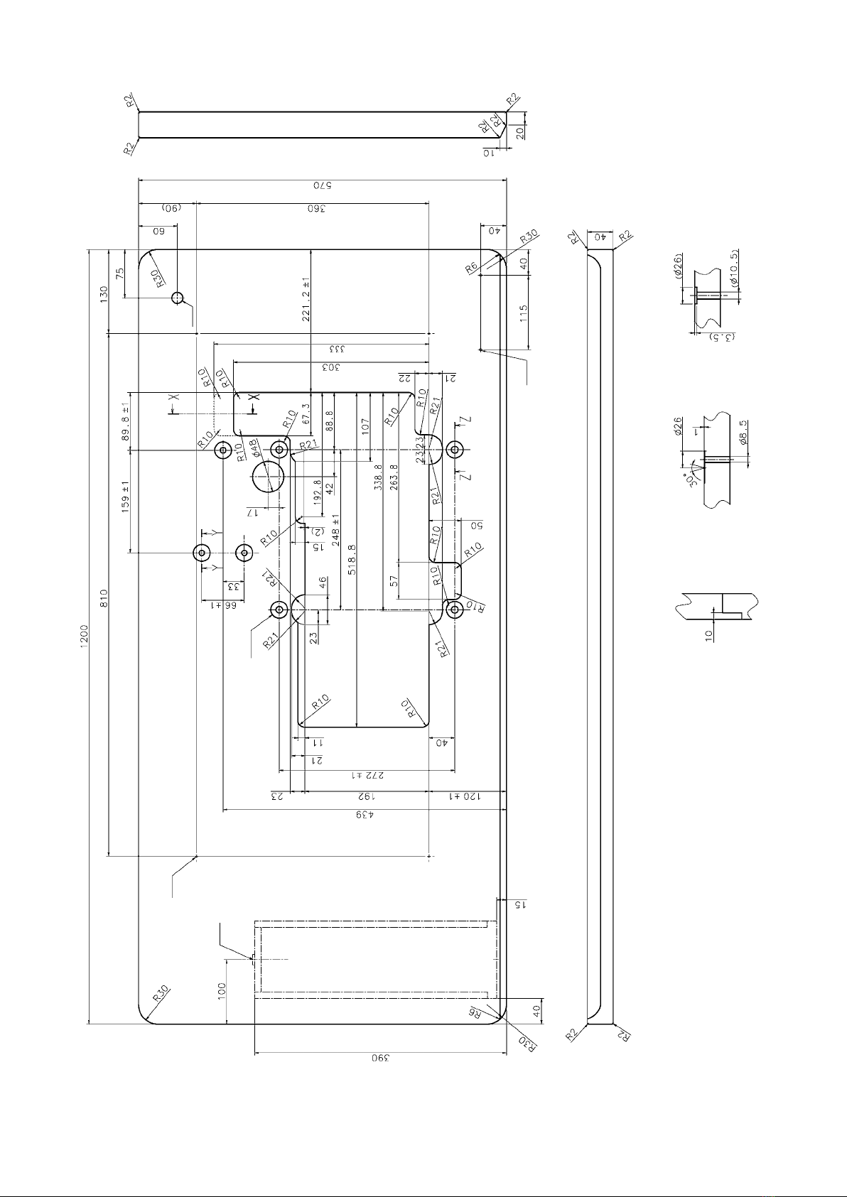
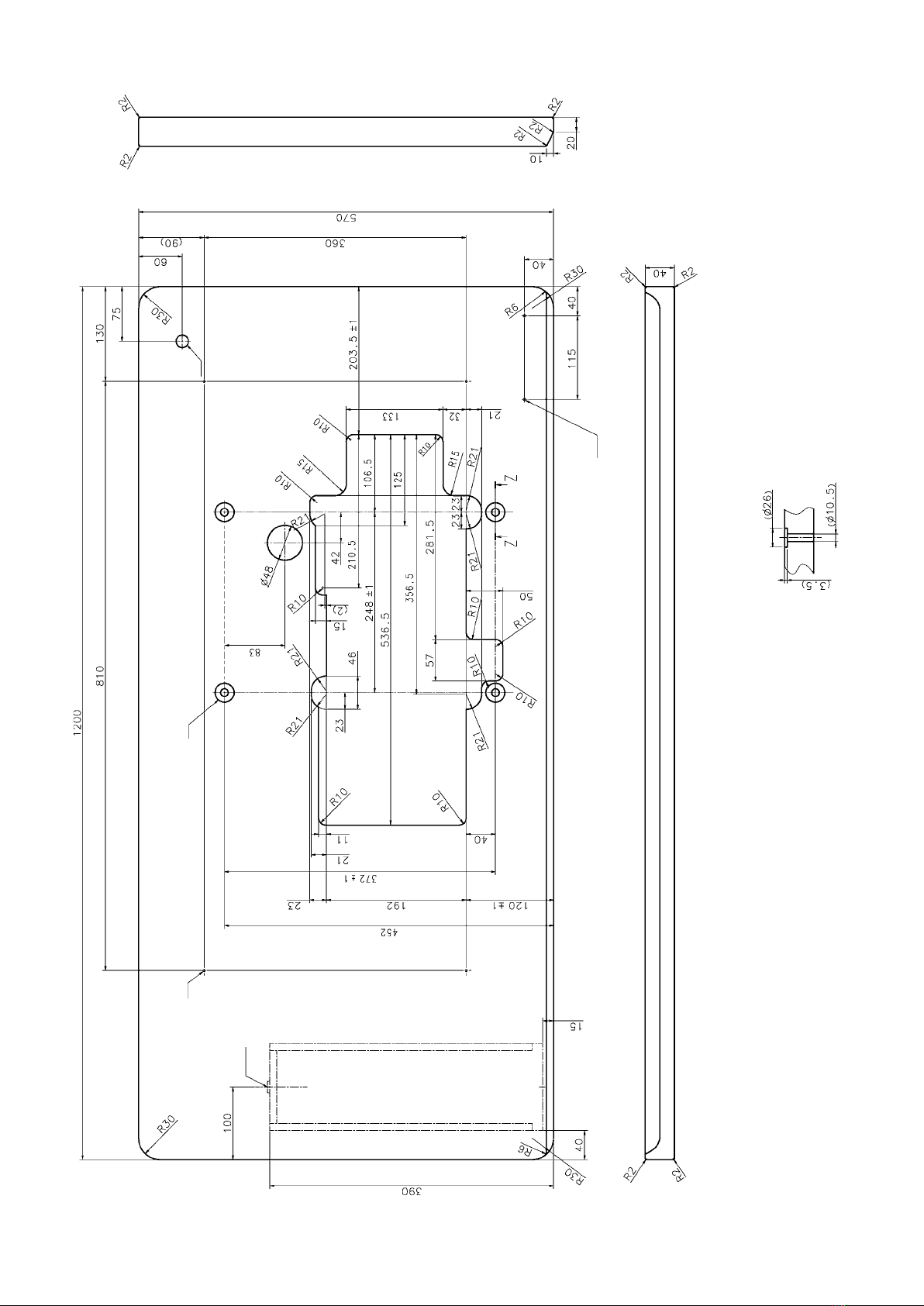
1. Installing the machine head onto the table................................................................................ 3
2.Selecting the motor pulley and the belt....................................................................................... 7
3.Installing the motor ....................................................................................................................... 7
4.Setting the belt............................................................................................................................... 7
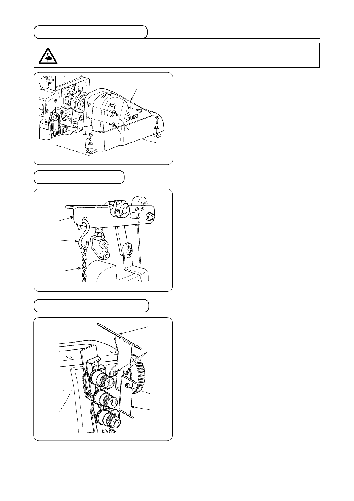
5.Installing the belt cover................................................................................................................. 8
6.Installing the chain ........................................................................................................................ 8
7.Installing the thread guide............................................................................................................ 8
8.Installing the needle bar thread take-up cover ........................................................................... 9
Ⅳ. LUBRICATION AND OILING ........................................................................................9
1.Lubricating oil................................................................................................................................ 9
2.Oiling............................................................................................................................................. 10
3.Silicon oil lubricating unit........................................................................................................... 10
Ⅴ. OPERATION................................................................................................................11
1.Needle........................................................................................................................................... 11
2.Attaching the needle ................................................................................................................... 11
3.Threading the machine head...................................................................................................... 12
4.Adjusting the stitch length ......................................................................................................... 13
5.Adjusting the differential feed ratio ........................................................................................... 13
6.
Adjusting the presser foot pressure ..................................................................................................14
7.Adjusting the thread tension...................................................................................................... 14
Ⅵ.
ADJUSTING THE SEWING MACHINE......................................................................................15
1.Adjusting the silicon container thread guide............................................................................ 15
2.Adjusting the needle bar thread take-up thread receiver ........................................................ 15
3.Adjusting the rocking thread take-up........................................................................................ 16
4.Adjusting the spreader thread guide......................................................................................... 16
5.Adjusting the looper thread cam................................................................................................ 16
6.Adjusting the looper thread cam eyelet .................................................................................... 17
7.Adjusting the looper.................................................................................................................... 17
8.Adjusting the height of the needle............................................................................................. 18
9.Adjusting the rear needle guard................................................................................................. 18
10.Relation between the rocking thread take-up timing and the needle thread loop ................ 19
(1) Adjustment by means of the crank ............................................................................................. 19
(2) Adjustment by the eccentric cam................................................................................................ 19
11.Adjusting the height of the feed dog ......................................................................................... 20
12.Installing position of the spreader............................................................................................. 20
13.Adjusting the spreader thread guide and the needle clamp thread guide............................. 21
14.Adjusting the front needle guard............................................................................................... 21
15.
Adjusting the presser foot lift ......................................................................................................22
16.Adjusting the micro-lifter............................................................................................................ 22
17.Adjusting the feed locus............................................................................................................. 23
(1) Changing the feed driving movement......................................................................................... 23
(2) Changing the feed rock movement ............................................................................................ 24
(3) Restoring to the standard adjustment ........................................................................................ 24
18.Adjustment value of balloon ...................................................................................................... 25
19. Adjustment of the feed dog in longitudinal direction ............................................................. 27
(1) Longitudinal position of the feed dog.......................................................................................... 27
(2) For C11....................................................................................................................................... 28
Ⅶ.
MAINTENANCE ...................................................................................................................29
1. Cleaning the sewing machine ................................................................................................... 29
2. Replacing the lubricating oil...................................................................................................... 29
3. Inspecing and replacing the oil lter ........................................................................................ 29

– 1 –– 1 –‒ 1 ‒
Model name High-speed, at-bed coverstitch machine
Model MF-7500 series
Stitch type ISO standard 406, 407, 602, and 605
Example of application Hemming and covering for knits and general knitted fabrics
Sewing speed Max. 6,500 sti/min (at the time of intermittent operation) V-belt type
6,000 sti/min (at the time of intermittent operation) Direct-drive type
Factory-set sewing speed at the time of shipment.
4,500 sti/min (at the time of intermittent operation)
Needle gauge 3-needle ... 4.8 mm, 5.6 mm, and 6.4 mm
2-needle ... 3.2 mm and 4.0 mm
Differential feed ratio 1 : 0.7 to 1 : 2 (stitch length : less than 2.5 mm)
Micro-differential feed adjustment mechanism is provided. (Micro-adjustment)
Stitch length 1.2 mm to 3.6 mm (can be adjusted up to 4.4 mm)
Needle UY128GAS #9S to #12S (standard #10S)
Needle bar stroke 31mm (or 33 mm when changing over the eccentric pin)
Dimensions (Height) 451 x (Width) 515 x (Length) 263
Weight 46kg
Lift of presser foot 8 mm (needle gauge : 5.6 mm without top covering), and 5 mm (with top covering)
Micro-lifter mechanism is provided.
Feed adjustment method Main feed ... dial type stitch pitch adjustment method
Differential feed ... lever adjustment method (micro-adjustment mechanism is provided.)
Looper mechanism Spherical rod drive method
Lubricating system Forced lubrication method by gear pump
Lubricating oil JUKI GENUINE OIL 18
Oil reservoir capacity Oil gauge lower line : 600 cc to upper line : 900 cc
Installation Semi-submerged type
Noise
- Equivalent continuous emission sound pressure level (LpA) at the workstation :
A-weighted value of 76.5 dB; (Includes KpA = 2.5 dB); according to ISO 10821- C.6.2 -ISO 11204
GR2 at 4,500 sti/min.
. SPECIFICATIONS

– 2 –– 2 –‒ 2 ‒
. CONFIGURATION OF THE MACHINE COMPONENTS
Presser spring regulator Eye guard cover
Needle bar thread take-up cover Throat plate
Oil circulation inspection windows Needle tip silicon oil lubricating unit
Oil hole cap Differential lock nut
Micro-lifter Micro-adjustment knob
Needle thread silicon oil lubricating unit Finger guard
Thread guide No. 1 Rocking thread take-up
Upper pulley Front cover
Thread tension nut Needle bar thread take-up thread receiver
Oil gauge Silicon container thread guide
Feed regulating knob Belt cover

– 3 –– 3 –‒ 3 ‒
[For the V-belt type]
Attach the supporting board and the rubber seats as shown
in the illustration and properly install the sewing machine.
Bolt
Spacer
Washer
Spring washer
Nut
Supporting board
Spring pin
Rubber cushion (Black) × 3
Rubber cushion (Gray) × 1
1. Installing the machine head onto the table
Semi-submerged type
WARNING :
Do not insert the power plug of the motor into the receptacle until all works have been completed. There
is a danger of injury by being caught in the machine.
WARNING :
The weight of the sewing machine is more than 46 kg. Be sure to perform the work with two persons or
more in case of unpacking, transportation or installation.
.
INSTALLATION
[For the direct-drive type]
Attach the supporting board and the rubber seats as shown
in the illustration and properly install the sewing machine.
Bolt
Spacer
Washer
Spring washer
Nut
Supporting board
Spring pin
Rubber cushion (Black) × 2
Rubber cushion (Gray) × 2
Semi-submerged type

– 4 –– 4 –‒ 4 ‒
Part No. Part name Q'ty
40072505 Dust-proof rubber (Gray) 1
13155403 Dust-proof rubber (Black) 3
■Installing the rubber cushion
Install the gray dust-proof rubber to section A only.
[For the V-belt type]
Part No. Part name Q'ty
40072505 Dust-proof rubber (Gray) 2
13155403 Dust-proof rubber (Black) 2
[For the direct-drive type]

– 5 –– 5 –‒ 5 ‒
DRAWING OF TABLE (SEMI-SUBMERGED TYPE)
For the V-belt type
4x ø 3.4 on the bottom surface, depth 20
(Drill a hole at the time of set-up.)
4x10.5 hole, depth 26, spot facing depth 3.5
2x ø 3.4 on the bottom surface, depth 10
(Drill a hole at the time of set-up.)
Drilled hole 17
Installing position of drawer stopper (on the reverse side)
Z-Z(4 locations)
Y-Y(3 locations)X-X

– 6 –– 6 –‒ 6 ‒
DRAWING OF TABLE (SEMI-SUBMERGED TYPE)
For the direct-drive type
4 x ø 3.4 on the bottom surface, depth 20
(Drill a hole at the time of set-up.)
4 x10.5 hole, depth 26, spot facing depth 3.5
2 x ø 3.4 on the bottom surface, depth 10
(Drill a hole at the time of set-up.)
Drilled hole 17
Installing position of drawer stopper (on the reverse side)
Z-Z(4 locations)

– 7 –– 7 –‒ 7 ‒
2. Selecting the motor pulley and the belt
* The table shows the numbers when a 3-phase
2-pole 400 W clutch motor (1 / 2 HP) is used.
* The commercially-available motor pulley near to
the counted value is designated since the outside
diameter of the commercially-available motor pulley
counts by 5 mm.
Use a motor pulley which is adaptable to
this sewing machine. The sewing speed
exceeds the max. sewing speed of this
sewing machine and machine trouble will
be caused unless a motor pulley which is
adaptable to this sewing machine is used.
When you use a new sewing machine, use
the machine at a speed of 4,500 sti/min or
less for the rst 200 hours (approximately
one month). A good result can be obtained
in terms of the durability.
Motor pulley and belt
Speed of
stitch
(sti/min)
50Hz 60Hz
Pulley size Belt size Pulley size Belt size
4,500 ø 100 M-35 ø 85 M-35
4,800 ø 105 M-36 ø 90 M-35
5,000 ø 115 M-36 ø 95 M-35
5,500 ø 125 M-37 ø 105 M-36
5,800 ø 130 M-37 ø 110 M-36
6,000 ø 135 M-37 ø 115 M-37
6,200 ø 140 M-38 ø 120 M-38
6,500 ø 150 M-39 ø 125 M-38
3. Installing the motor
Motor pulley
5.5
mm
10 mm
M type V belt
Use a clutch motor of 3-phase, 2-pole, 400 W (1/2HP).
Use the M type V belt.
1) The motor pulley shifts to the left-hand side when de-
pressing the pedal. At this time, install the motor so
that the centers of motor pulley and lower pulley align
with each other.
* For the installing procedure of the motor pulley, refer to
the Instruction Manual for motor.
Lower pulley
2) Install the motor so that the pulley rotates clockwise.
If the machine pulley rotates in the reverse
direction, nomal lubrication cannot be per-
formed. As a result, machine trouble will
be caused.
4. Setting the belt
WARNING :
When replacing the belt, be sure to turn OFF the power to the motor and ascertain that the motor has
totally stopped rotating before starting the work. There is a danger of injury since hands or clothes may
be caught in the belt.
1) Fit belt to lower pulley .
2) Turning upper pulley , set the other side of the belt to
motor pulley .
3) Adjust the belt tension so that the belt sags 15 to 20
mm when the center of the belt is pressed with an ap-
proximate 10N (1.02 kgf) load.
4) Securely x the belt with lock nut when the belt has
been set.
15 - 20 mm
If the deection of the belt is excessive
when the sewing machine is operated,
check again the belt tension.
40˚

– 8 –– 8 –‒ 8 ‒
Install belt cover as shown in the illustration.
and are the xing screws for belt cover .
5. Installing the belt cover
WARNING :
Be sure to install the belt cover. If it is not installed, there is a danger of injury since hands or clothes may be caught
in the machine or a danger of damage of the machine since sewing products may be caught in the machine.
1) Hang hook of chain to presser bar lifting lever .
2) Hook the other side of the chain to the pedal.
1) Install thread guide No. 1 supplied as accessories
on the machine arm with screws (black, screw shank
length 6 mm) .
2) Install thread guide on thread guide No. 1 with
screw (black, screw shank length 6 mm) .
7. Installing the thread guide
6. Installing the chain

– 9 –– 9 –‒ 9 ‒
<When using the sewing machine for the rst time>
Lubricating oil has been taken out at the time of delivery.
Be sure to supply lubricating oil before using the sewing
machine for the rst time.
• Oil used : JUKI GENUINE OIL 18
Do not use oil addition agent since deterio-
ration of lubricating oil or machine trouble
will be caused.
To add oil, remove first the oil inlet cap indicated as
"OIL". Then, add oil from the oil inlet until the oil surface
reaches the middle of the upper and lower marker lines on
oil gauge .
<Checking before using the sewing machine>
1) Check oil gauge and make sure that lubricating oil
level is between the upper and lower two lines. When
lubricating oil level lowers below the lower line, supply
lubricating oil.
2) Make sure that lubricating oil comes out from the
nozzle of oil circulation identication window when
rotating the sewing machine. When lubricating oil does
not come out, perform “-3Inspecting and replac-
ing the oil lter”. (See page 29.)
8. Installing the needle bar thread take-up cover
1. Lubricating oil
Lubrication
. LUBRICATION AND OILING
Install the needle bar thread take-up cover supplied with
the unit on the machine arm with two screws .

– 10 –– 10 –‒ 10 ‒
3. Silicon oil lubricating unit
This sewing machine is provided with the silicon oil lubricating
unit as standard.In case of sewing at a high speed, or using
chemical thread or chemical fabric, use the silicon oil lubricat-
ing unit to prevent thread breakage or stitch skipping.
Oil used is silicon oil (dimethyl silicon).
Open cover of silicon container and make sure that
silicon oil enters needle thread, needle tip and silicon oil
lubricating unit. If silicon oil is insufcient there, supply it
(dimethyl silicon).
When silicon oil adhered to the components
other than the silicon oil lubricating unit,
be sure to wipe it out. If the components to
which silicon oil adhered are kept without
wiping out the oil, sewing machine trouble
will be caused.
When you operate the sewing machine for the rst time or
after an extended period of disuse, be sure to apply 2 to 3
drops of lubricating oil to needle bar .
For the lubricating oil, use JUKI GENUINE OIL 18.
2. Oiling
WARNING :
To protect against possible personal injury due to abrupt start of the machine, be sure to start the follow-
ing work after turning the power off and ascertaining that the motor is at rest.

– 11 –– 11 –‒ 11 ‒
Japan No. 9 10 11 12 14
German No. 65 70 75 80 90
1. Needle
The needle used for this sewing machine is UY128GAS.
For the needle No., select a proper needle in accordance with
the sewing conditions.
2. Attaching the needle
WARNING :
To protect against possible personal injury due to abrupt start of the machine, be sure to start the follow-
ing work after turning the power off and ascertaining that the motor is at rest.
1) Loosen setscrew of needle with a screwdriver.
2) Hold the new needle with indented part facing to the
rear and insert it into the hole in needle clamp until
the end of hole is reached.
3) Securely tighten setscrew of the needle.
Scarf
. OPERATION

– 12 –– 12 –‒ 12 ‒
WARNING :
To protect against possible personal injury due to abrupt start of the machine, be sure to start the follow-
ing work after turning the power off and ascertaining that the motor is at rest. If threading is wrong, stitch
skipping, thread breakage, needle breakage or irregular stitches will be caused. So, be careful.
3. Threading the machine head
When using more stretchable
thread
When covering thread is excessively
loosened =
When covering thread is excessively
loosened even after passing =
When covering thread is exces-
sively tense =
Broken lines when stretcher thread
is used
When using less stretchable
thread
Broken line when using more stretchable thread
Thread the machine head according to the following threading illustrations.

– 13 –– 13 –‒ 13 ‒
4. Adjusting the stitch length
WARNING :
To protect against possible personal injury due to abrupt start of the machine, be sure to start the follow-
ing work after turning the power off and ascertaining that the motor is at rest.
The stitch length can be innitely adjusted from 1.2 mm to
3.6 mm.
* The actually sewn stitch length varies in accordance
with kind and thickness of the materials.
[How to change the stitch length]
Turn clockwise feed regulating knob to increase the
stitch length.
Turn it counterclockwise to decrease the stitch length.
• When making the stitch length 3.6 mm or more
Loosen screw and turn clockwise feed regulating knob
to regulate the stitch length.
Push pin until it goes to the end, and x it with screw .
Use the machine within the range where feed dogs or feed
dog and throat plate do not come in contact with each oth-
er.
Loosen differential lock nut and move lever up to
increase the differential feed ratio. Then the sewn material
is gathered.
Move lever down to decrease the differential feed ratio.
The differential feed ratio becomes 1 : 1 at the position
where the pointer of lever is on the long scale. Note
that two scales on the upper side show 1 : 1.4 and 1 : 2
respectively, and one on the lower side 1 : 0.7.
Fine adjustment of the differential feed ratio can be per-
formed with micro-adjustment knob .
There is a case where feed dogs or feed
dog and throat plate come in contact with
each other by the aforementioned adjust-
ment according to the relation between the
stitch length and the differential feed ratio.
So, be very careful.
5. Adjusting the differential feed ratio
Gathering
Stretching

– 14 –– 14 –‒ 14 ‒
Decrease the presser foot pressure as low as possible to
such an extent that stitches are stabilized.
To adjust the pressure, loosen lock nut of presser
spring regulator and turn presser spring regulator .
After the adjustment, tighten lock nut .
Turning it clockwise to increase the pressure.
Turning it counterclockwise to decrease the pressure.
6.
Adjusting the presser foot pressure
7. Adjusting the thread tension
Adjust the thread tension with the following thread tension
nuts.
Needle thread tension nut
Top covering thread tension nut
Looper thread tension nut
Turn clockwise to increase the thread tension.
Turn counterclockwise to decrease the thread tension.
=Decrease
=Increase

– 15 –– 15 –‒ 15 ‒
.
ADJUSTING THE SEWING MACHINE
1) Loosen setscrews and shift them to the lower-
most position. Then, tighten setscrews .
2) Loosen setscrew . Move the needle thread guide
bar to adjust so that a distance of 29 mm is provid-
ed between its center and the center of screws .
Then, x the needle thread bar at that position with
setscrew .
1. Adjusting the silicon container thread guide
WARNING :
To protect against possible personal injury due to abrupt start of the machine, be sure to start the follow-
ing work after turning the power off and ascertaining that the motor is at rest.
3) Loosen setscrews and adjust so that the heights
of the respective needle thread guide rods are the
dimensions as shown in the illustration. Then tight-
en screws to x the thread guide rods.
A B C
29mm 17mm 5mm
Loosen setscrew and adjust so that the bottom end to
the center of the thread hole of needle bar thread take-
up aligns with the top end of needle bar thread take-
up thread receiver when the needle bar is in its lowest
position. Then tighten screw to x the needle bar thread
take-up thread receiver.
2. Adjusting the needle bar thread take-up thread receiver
WARNING :
To protect against possible personal injury due to abrupt start of the machine, be sure to start the follow-
ing work after turning the power off and ascertaining that the motor is at rest.
C
B
A
29 mm

– 16 –– 16 –‒ 16 ‒
1) Loosen setscrews . Move rocking thread take-up
lever to the right and left to adjust so that a distance
of 83 mm is provided between the thread hole and the
center of rocking thread take-up lever shaft . Then,
tighten setscrews .
2) Adjust so that rocking thread take-up base is level
when the rocking thread take-up is in its lowest position.
Retighten screw to x the rocking thread take-up base.
3. Adjusting the rocking thread take-up
WARNING :
To protect against possible personal injury due to abrupt start of the machine, be sure to start the follow-
ing work after turning the power off and ascertaining that the motor is at rest.
4. Adjusting the spreader thread guide
WARNING :
To protect against possible personal injury due to abrupt start of the machine, be sure to start the follow-
ing work after turning the power off and ascertaining that the motor is at rest.
Adjust so that the top end of thread guide thread path (rear)
of spreader thread guide aligns with the bottom sur-
face of slot of spreader thread take-up when spreader
thread take-up is in its highest position. Then tighten
screw to x the spreader thread guide.
5. Adjusting the looper thread cam
WARNING :
To protect against possible personal injury due to abrupt start of the machine, be sure to start the follow-
ing work after turning the power off and ascertaining that the motor is at rest.
Adjust so that thread comes off from the highest place of looper thread cam when needles come down and the top
end of left needle aligns with the bottom surface of looper . Then tighten screws to x the looper thread cam.
Thread
83mm

– 17 –– 17 –‒ 17 ‒
6. Adjusting the looper thread cam eyelet
WARNING :
To protect against possible personal injury due to abrupt start of the machine, be sure to start the follow-
ing work after turning the power off and ascertaining that the motor is at rest.
When the thread drawing amount is desired to be de-
creased in case of 2-needle machine or the like, loosen
screws , move upward thread guides and and
tighten screws to x them.
= Decrease = Increase
Standard adjustment is achieved in the following state:
The lower end face of the thread guide is aligned with
the marker dot
The right and left thread guide thread paths are leveled
7. Adjusting the looper
WARNING :
To protect against possible personal injury due to abrupt start of the machine, be sure to start the follow-
ing work after turning the power off and ascertaining that the motor is at rest.
[Lateral position]
The relation between clearance A between looper and
the center of right-hand needle and the needle gauge is as
shown in the table.
[Longitudinal position]
Adjust so that the clearance between blade point of the
looper and medium needle is 0 to 0.05 mm when the
top end of the looper comes from the extreme right posi-
tion to the center of the medium needle. After the adjust-
ment, tighten clamp screw to x the looper.
* The blade point of the looper comes in contact with the
right-hand needle when rear needle guard does not
work. So, be careful.
Loosen clamp screw and laterally adjust looper holder
in accordance with the table.
Unit : mm
2-needle 3-needle
Needle gauge Return amount A Needle gauge Return amount A
3.2 4.9
4.0 4.5
4.8 4.1 4.8 4.1
5.6 3.7 5.6 3.7
6.4 3.3 6.4 3.3
0 - 0.05 mm
A
The right and
left thread guide
thread paths
are leveled
The lower end
face of the
thread guide
is aligned with
the marker dot

– 18 –– 18 –‒ 18 ‒
WARNING :
To protect against possible personal injury due to abrupt start of the machine, be sure to start the follow-
ing work after turning the power off and ascertaining that the motor is at rest.
1) Equally adjust clearance A between needles and
needle holes in the throat plate.
2) Adjust the height of the needle bar so that the top end
of the needle hole of left-hand needle aligns with the
bottom end section of the looper when the looper trav-
els to the extreme right end and top end B of the looper
protrudes by approximately 1 mm from the left end of
the left-hand needle, remove the rubber cap in the
face plate, and tighten needle bar bracket setscrew
to x the needle bar.
Unit : mm
Adjust the lateral position of rear needle guard so that it
receives the needle within the range of B when the needle
is in its lowest position.
1) Adjust the height with setscrew so that edge line A
of rear needle guard enters in the needle hole of
right-hand needle when the needle bar is in its lowest
position.
2) Make rear needle guard slightly come in contact with
the right-hand needle so that the clearance between
right-hand needle and top end of the looper is 0 to
0.05 mm when top end of the looper comes from the
extreme right end to the center of right-hand needle.
In addition, make rear needle guard slightly come
in contact with the medium needle so that the clear-
ance between the medium needle and top end of
the looper keeps 0 to 0.05 mm when top end of the
looper comes to the center of medium needle.
Perform the adjustment with setscrews and .
9. Adjusting the rear needle guard
WARNING :
To protect against possible personal injury due to abrupt start of the machine, be sure to start the follow-
ing work after turning the power off and ascertaining that the motor is at rest.
A
B
C
2-needle 3-needle
Needle
gauge
Height of left-
hand needle, C
Needle
gauge
Height of left-
hand needle, C
3.2 9.7
4.0 9.3
4.8 8.8 4.8 8.8
5.6 8.5 5.6 8.5
6.4 8.0 6.4 8.0
Reference : Height from the top surface of the throat plate
to the top end of left-hand needle, Cwhen
the needle is in the higher dead point is as
shown in the table.
8. Adjusting the height of the needle
0,1 - 0,3 mm
4,5 - 5,5 mm 16 - 18 mm
8,3 - 8,7 mm
B
A
Other manuals for MF-7500 Series
3
Table of contents
Other JUKI Sewing Machine manuals

JUKI
JUKI DU-141H-4 User manual

JUKI
JUKI PLK-J12060 User manual

JUKI
JUKI LK-1900B series Quick start guide

JUKI
JUKI Q141 User manual

JUKI
JUKI DDL-5600N Series User manual

JUKI
JUKI MEB-3200C User manual

JUKI
JUKI AMS-224EN6060/IP-420 User manual

JUKI
JUKI TL-2000Qi User manual

JUKI
JUKI LH-3126F Installation guide

JUKI
JUKI UnionSpecial 35800BLWG Setup guide

JUKI
JUKI DNU-1541 User manual

JUKI
JUKI IP-310 User guide

JUKI
JUKI LK-1910 User manual

JUKI
JUKI HZL-DX3 User manual

JUKI
JUKI LZ-2290A/IP-110A/SC-915 User manual

JUKI
JUKI M-1 Series User manual

JUKI
JUKI APW-895 Quick start guide

JUKI
JUKI MO-613V User manual

JUKI
JUKI K-1E User manual

JUKI
JUKI DLU-5490N User manual