JUKI LZ-2280A Series User manual

LZ-2280A Series
INSTRUCTION MANUAL

CONTENTS
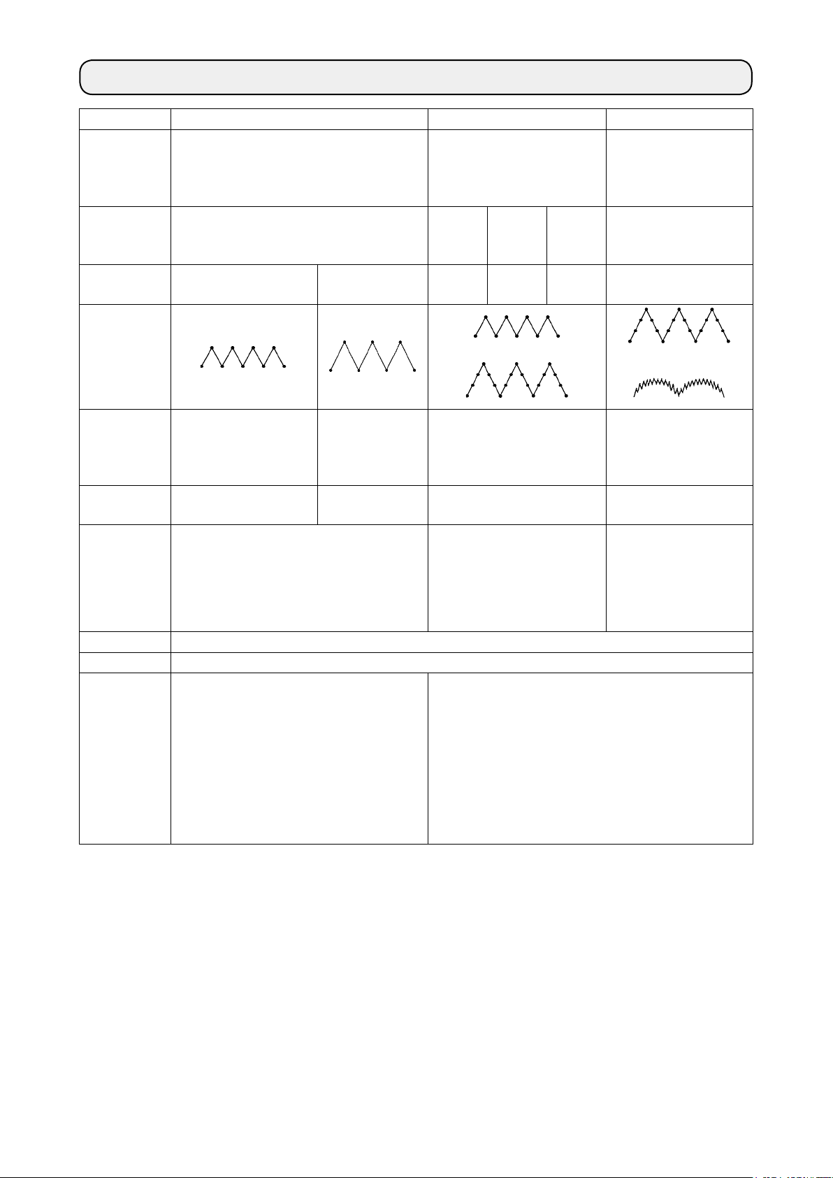
1. SPECIFICATIONS......................................................................................................... 1
2. INSTALLATION............................................................................................................. 4
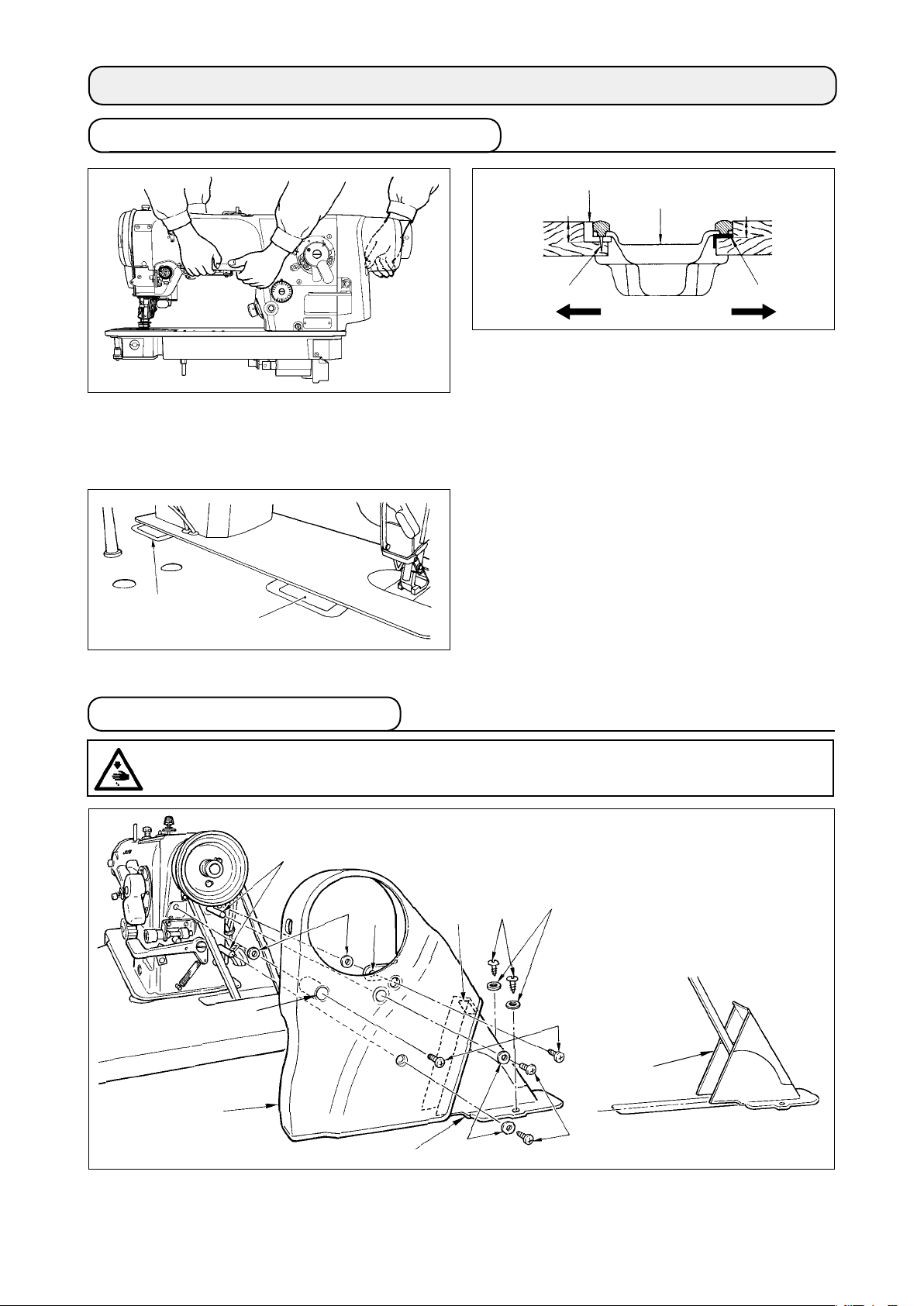
2-1. Installation of the sewing machine...............................................................................................4
2-2. Attaching the belt cover ................................................................................................................4
2-3. Inserting the needle .......................................................................................................................5
2-4. Installing the control panel ........................................................................................................... 6
3. PREPARATION OF THE SEWING MACHINE ............................................................. 6
3-1. Lubrication......................................................................................................................................6
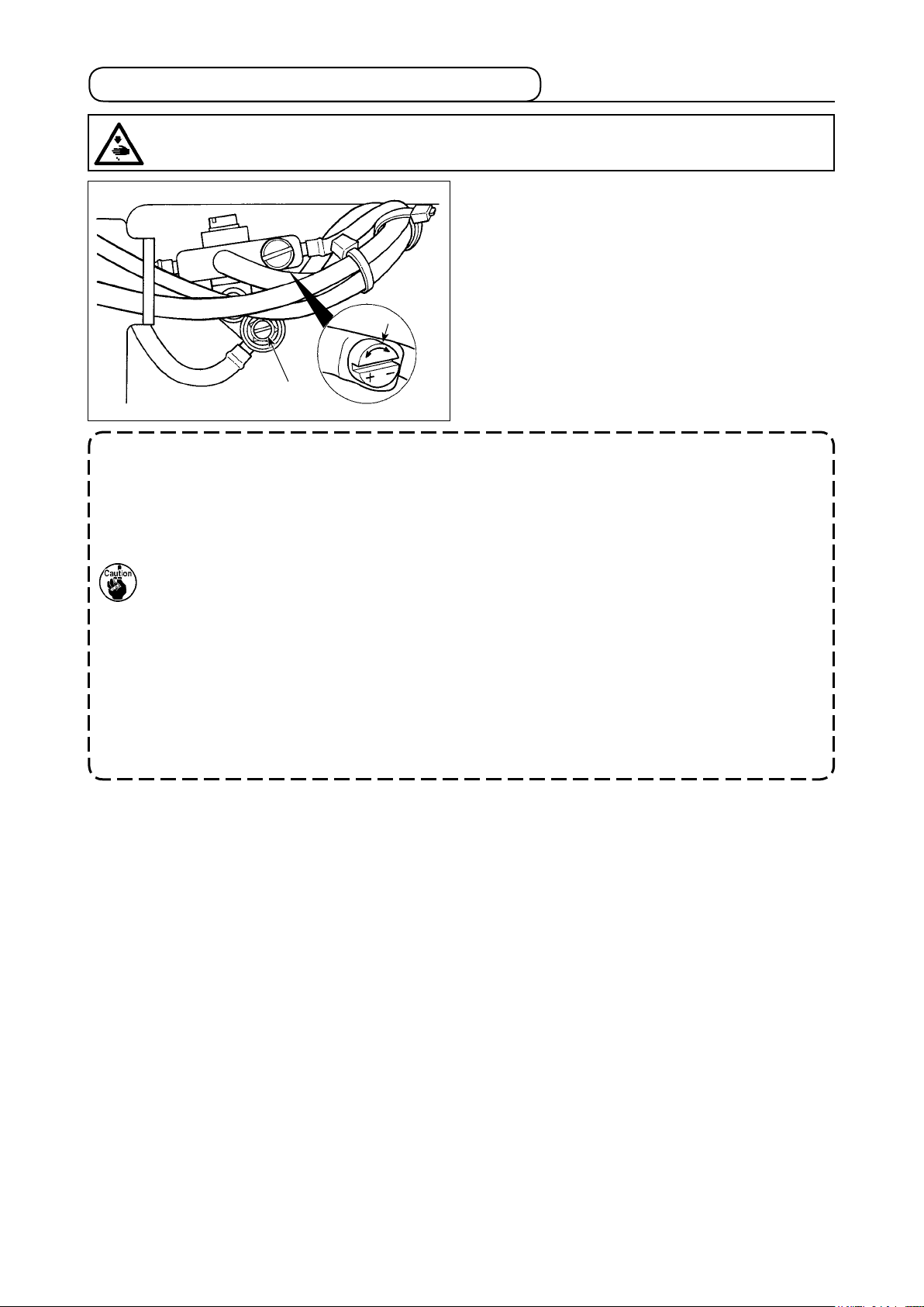
3-2. Adjusting the amount of oil in the hook ......................................................................................7
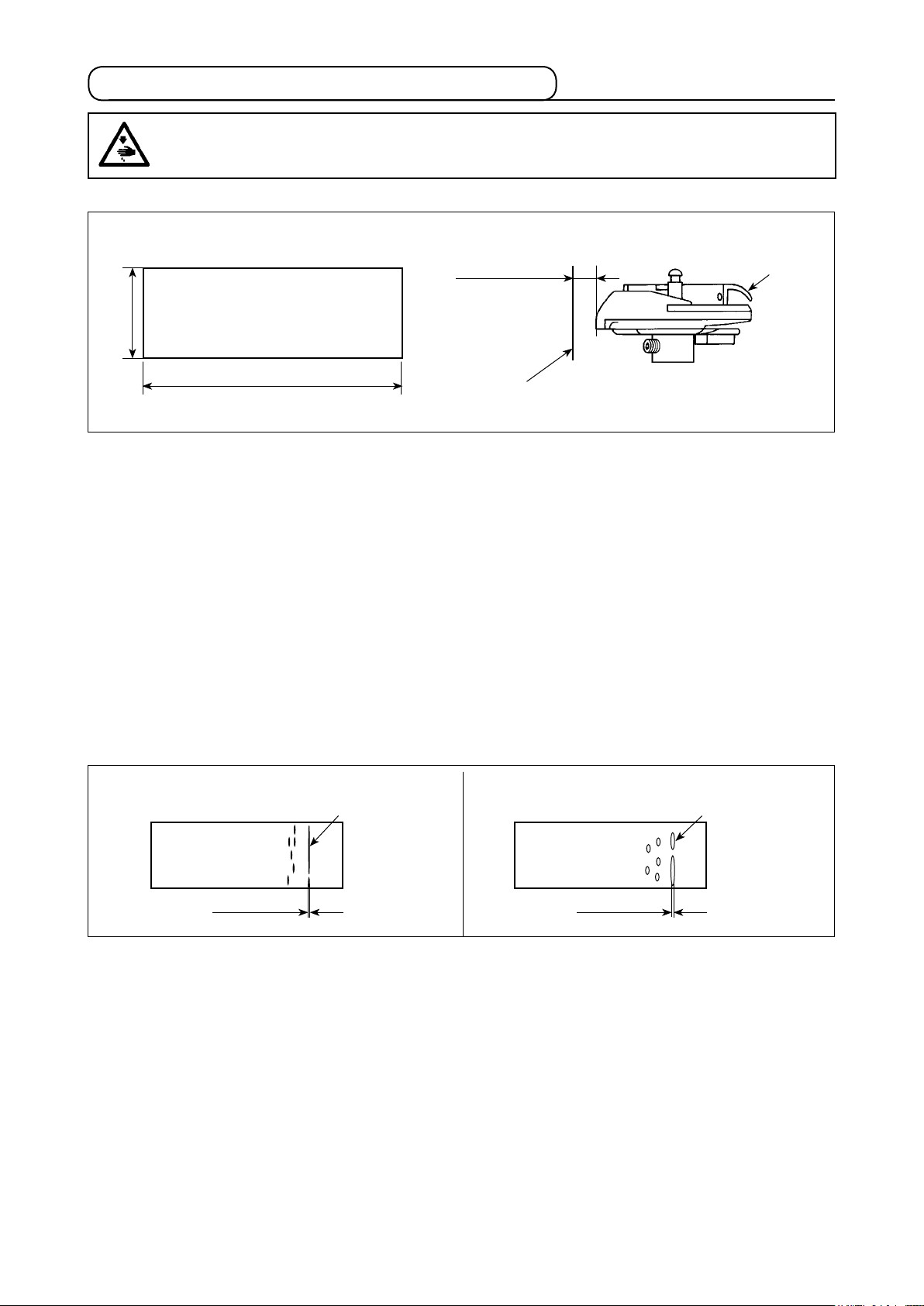
3-3. Adjusting the amount of oil (oil splashes)................................................................................... 8
3-4. Winding the bobbin thread............................................................................................................9
3-5. Inserting the bobbin case and the bobbin................................................................................. 10
3-6. Threading the machine head ...................................................................................................... 11
3-7. Adjusting the pedal...................................................................................................................... 11
4. ADJUSTING THE SEWING MACHINE ...................................................................... 12
4-1. Adjusting the thread tension ......................................................................................................12
4-2. Adjusting the zigzag width..........................................................................................................13
4-3. Adjusting the pressure of the presser foot ............................................................................... 14
4-4. Adjusting the height of the presser bar .....................................................................................14
4-5. Adjusting the micro-lifting mechanism of the presser foot ..................................................... 14
4-6. Adjusting the stitch length..........................................................................................................15
4-7. Adjusting the denser stitching ...................................................................................................15
4-8. Height and inclination of the feed dog....................................................................................... 16
4-9. Attaching/removing the hook .....................................................................................................16
4-10. Adjusting height of the needle bar ............................................................................................. 17
4-11. Adjusting the needle-to-hook timing and the needle guard..................................................... 17
4-12. Adjusting the stop position of the needle..................................................................................18
4-13. Adjusting the thread trimmer...................................................................................................... 19
4-14. Needle thread feeding device ..................................................................................................... 20
4-15. Position of the wiper.................................................................................................................... 20
5. OPERATION OF THE SEWING MACHINE................................................................ 21
5-1. How to operate the pedal (In the case of the direct-drive type sewing machine).................. 21
5-2. One-touch type reverse feed switch .......................................................................................... 21
5-3. Changing over the needle-throwing method............................................................................. 22
5-4. LED light ....................................................................................................................................... 22
6. OPTIONAL .................................................................................................................. 23
6-1. Pedal-operated reverse feed device (RF-1) ............................................................................... 23
6-2. Joining foot for the lockstitch presser foot............................................................................... 23
6-3. Auxiliary thread take-up kit .........................................................................................................23
7. MOTOR PULLEY AND BELT ..................................................................................... 24
8. TROUBLES AND CORRECTIVE MEASURES .......................................................... 25

– 1 –
Model LZ-2280A * LZ-2284A * LZ-2287A
Type of zigzag
Standard zigzag Selectable between standard
zigzag stitching and 3-step
zigzag stitching
Selectable between
3-step zigzag stitching
and 24-stitch standard
scallop zigzag stitching
Motor-drive
specication
V-belt V-belt/
Direct
drive
Direct
drive
V-belt/
Direct
drive
V-belt
Specication
[ * section]
A (Narrow width) B (Wide width) - -7 T -
Stitch diagram or or
Max. zigzag
width (mm)
5
[4 at the time of delivery]
8 3-step zigzag : 10
[8 at the time of delivery]
Standard zigzag : 5
[5 at the time of delivery]
10
[8 at the time of delivery]
Max. feed pitch
(mm)
2.5 (Normal/reverse feed)
[2 at the time of delivery]
5 (Normal feed)
4 (Reverse feed)
2.5 (Normal/reverse feed)
[2 at the time of delivery]
2.5 (Normal/reverse feed)
[2 at the time of delivery]
Max. sewing
speed (sti/min)
5,000 5,000
(3-step zigzag : Zigzag width
= less or 8 mm)
4,000
(3-step zigzag : Zigzag width
= more than 8 mm)
5,000
(Zigzag width
= less or 8 mm)
4,000
(Zigzag width
= more than 8 mm)
Needle SCHMETZ 438SUK (Nm75) : Nm65 to 90, DP x 134 (#10) : #9 to 14
Oil JUKI CORPORATION GENUINE OIL 7
Noise
-Equivalent continuous emission sound
pressure level (LpA) at the workstation:
A-weighted value of 80 dB; (Includes KpA
= 2.5 dB); according to ISO 10821- C.6.2 -
ISO 11204 GR2 at 4,500 sti/min.
-Equivalent continuous emission sound pressure level
(LpA) at the workstation:
A-weighted value of 80 dB; (Includes KpA = 2.5 dB);
according to ISO 10821- C.6.2 - ISO 11204 GR2 at 4,400
sti/min.
-Sound power level (LWA);
A-weighted value of 84.6 dB; (Includes KWA = 2.5 dB);
according to ISO 10821- C.6.2 - ISO 3744 GR2 at 4,500
sti/min.
1. SPECIFICATIONS

– 2 –
■DRAWING OF TABLE
(1) For the V-belt type
195
480
(525)
40
(21)
15
390
100
22.5
136
(22.5)
181 0
-1
110
(244)
80
68.1±0.5
80
R20
R22.5
Z
Z
R30
R30
Y
Y
R18
R22.5
T
T
R10
R10
R20
R22.5
29
50
50
90
1200
U
U
W
W
C1.5~C2.5(ひんじ側のみ)
VV
R18
R22.5
40
70
200
535
25.5
10
R30
R30
R30
R30
R6
R6
50
91
500 300
(591)
28
141
139
43
86.5
21.5
21.5
84
18
75
52
9
14
R242.5
R242.5
17
55
27.5
100
195
52.5
90
R27.5
R27.5
S
S
20
360
810
R8
R8
R8
R8
R8
R8
R8
R8
40
125
X
239.7±1
(172.2)
R10
29
R10
X
80
140
137
(110)
225
225
188
140
159
66.5
476.5
112
40
54
50±1
70±1
308
C1
C1
R2
40
27
R2
R2
R30
R2
R2
6
W-W
R2
R2
R2
R2
R30
R30
R2
R2
R2
R2
14
10
U-U
17.5±0.5
X-X
22.5±0.5
Y-Y
18.5
±0.5
Z-Z T-T
1
∅8.5
8
∅26
V-V(1:1)
21 +0.5
0
20
+0.5
0
S-S
J
A
B
C
D
E
F
H
G
I
K
L
A 4×ø3.4 on the bottom surface, depth 20 (drill a hole at the time of set-up.)
B Installing position of drawer stopper (on the reverse side)
C ø16 depth 30
D ø18 drilled hole
E 3×ø13 drilled hole
F 2×ø3.5 depth 10
G 2×ø3.5 depth 10
H 2×ø3.4 on the bottom surface, depth 10 (drill a hole at the time of set-up.)
I ø35±0.5 drilled hole
J JUKI logotype
K 2×ø3.4 on the bottom surface, depth 20
L 2×ø3.5 depth 4
(Hinge side only)

– 3 –
50
20
X
X
Y
Y
Z
Z
125
310
166.5
VV
V V
144
195
480
(525)
40
(21)
15
390
100
22.5
136
(22.5)
181 0
-1
110
(244)
80
68.1±0.5
80
R20
R22.5
Z
Z
R30
R30
Y
Y
R18
R22.5
T
T
R10
R10
R20
R22.5
29
90
1200
U
U
WW
VV
R18
R22.5
40
70
535
10
R30
R30
R30
R30
R6
R6
50
91
500 300
(591)
141
139
43
86.5
21.5
21.5
84
18
75
52
9
14
R242.5
R242.5
17
55
27.5
100
195
52.5
90
R27.5
R27.5
S
S
20
360
810
R8
R8
R8
R8
R8
R8
40
125
X
239.7±1
(172.2)
R10
29
R10
X
80
140
137
188
C1.5~C2.5(ひんじ側のみ)
17.5±0.5
X-X
22.5±0.5
Y-Y
18.5
±0.5
Z-Z T-T
1
∅8.5
8
∅26
V-V(1:1)
C1
C1
R2
40
27
R2
R2
R30
R2
R2
6
W-W
R2
R2
R2
R30
R30
R2
R2
R2
R2
14
10
U-U
21
+0.5
0
20
+0.5
0
S-S
R2
J
A
B
C
D
E
F
H
G
I
(2) For the direct-drive type
A 4×ø3.4 on the bottom surface, depth 20 (drill a hole at the time of set-up.)
B Installing position of drawer stopper (on the reverse side)
C ø16 depth 30
D ø18 drilled hole
E 3×ø13 drilled hole
F 2×ø3.5 depth 10
G 2×ø3.5 depth 10
H 2×ø3.4 on the bottom surface, depth 10 (drill a hole at the time of set-up.)
I ø40±0.5 drilled hole
J JUKI logotype
(Hinge side only)

– 4 –
1) Securely attach two belt cover studs ❶to the screw holes in the machine arm.
2) Put setscrews ❸in hole Aof belt cover A ❷and section B, and x them with setscrew washers ❹.
3) Attach belt cover A ❷to the machine arm from the slanted rear side so that it covers the belt.
2-2. Attaching the belt cover
2) Attaching the oil pan
Hammer the nails ❷on the two support rubber
seats ❶of the machine head on operators' side
A of the protruding section of the table, and x
the two cushion seats ❸of the machine head on
hinging side Bwith rubber adhesive agent. Now,
put the oil pan ❹on the cushions.
3) Attaching the hinge
Fit the hinge ❶in the hole in the bed and engage
it with the rubber hinge ❷of the table. Put the
machine head down on the cushions located at
the four corners.
WARNING :
To protect against possible personal injury due to abrupt start of the machine, be sure to start the
following work after turning the power off and ascertaining that the motor is at rest.
1) Carry the sewing machine with two persons as
shown in the gure.
2-1. Installation of the sewing machine
2. INSTALLATION
❶
❷❸
❹
AB
22.5 mm 18.5 mm
❷
❶
❶
❷
❺
❹
❸
❻
❼
❽❾
A
BC
❼

– 5 –
■In case of using a market-available needle positioner
Adjust so that the needle always stops at the position higher than the cloth to make the sewing work very
effective. In this case the needle positioner can be used.
Install the needle positioner in the manner as described below.
If the commercially-available needle positioner is used, a separately-available exclusive part should
be purchased.
•Synchronizer support ❷part No. : 22535462 1 pc
•Adapter ❸part No. : 40109125 1 pc
4) Fix setscrews ❸to the screw holes in the machine arm, and washers ❺and setscrews ❻to the belt
cover supports.
5) Insert belt cover B asm. ❼from the rear of belt cover A ❷ and x it at the position where rubber section
Cof belt cover B asm. ❼lightly comes in contact with the belt cover A. At this time, attach the belt cover
B asm. at the position where the light and left sides are equal in terms of the long hole of the table with
wood screw ❽and washer ❾.
1) Install adapter ❸to the rear end section of the
main shaft.
2) Loosen four setscrews in belt cover A ❶and
temporarily tighten them.
3) Remove the setscrew in hole Aamong the four
setscrews and x synchronizer support ❷to the
belt cover stud.
Then perform nal tightening of the setscrews of
the whole belt cover.
4) Attach the synchronizer ❹of the needle position-
er as shown in the gure on the left.
❶
❸
❷
A
❹
1) Turn the handwheel by hand to raise the needle
bar to the highest point.
2) Loosen the needle clamp screw ❷. Hold the
needle ❶so that the long groove Bon the nee-
dle is facing exactly toward you.
3) Insert the needle deep into the hole of the needle
bar in the direction of the arrow until it will go no
further.
4) Securely tighten the screw ❷.
5) Conrm that the long groove Bon the needle
faces toward you.
2-3. Inserting the needle
WARNING :
To protect against possible personal injury due to abrupt start of the machine, be sure to start the
following work after turning the power off and ascertaining that the motor is at rest.
❶
BA
❷

– 6 –
1) Put foamed polyurethane pad ❶in the oil pan ❷.
2) Fill the oil pan ❷with JUKI CORPORATION GEN-
UINE OIL 7 up to the level of “HIGH” mark A.
3) Add the oil as soon as the oil level comes down
to “LOW” mark Bor lower.
4) Run the sewing machine after the lubrication. As
long as the machine is lubricated normally, the oil
splash is seen through the oil sight window ❸.
(The amount of splashing oil does not depend on
the amount of oil.)
* If dust has gathered in the oil pan, remove it.
When changing the sewing machine oil, squeeze
urethane foam ❶and remove dust from it.
1. Whenusinganewsewingmachineforthersttimeorusingthesewingmachinewhichhasnot
been used for a long time, run the sewing machine at a low speed (approximately 2,000 sti/min)
for approximately ten minutes.
2. When the machine is continuously used at a low speed (2,000 sti/min or less), make the machine
run idle at a high speed (4,000 sti/min or more) for approximately 5 minutes once a week.
3. Use clean oil and when the oil becomes dirty, replace it with clean oil as soon as possible. When
you continue to use the machine with dirty oil, the trouble will be caused.
3-1. Lubrication
3. PREPARATION OF THE SEWING MACHINE
WARNING :
To protect against possible personal injury due to abrupt start of the machine, be sure to start the
following work after turning the power off and ascertaining that the motor is at rest.
2-4. Installing the control panel
WARNING :
To protect against possible personal injury due to abrupt start of the machine, be sure to start the
following work after turning the power off and ascertaining that the motor is at rest.
In the case the sewing machine with a direct-drive
motor is used, install the control panel to the sewing
machine.
The control panel comes in four different types.
Panel Part No. Remarks
CP-18A 40088591 Simplied type
CP-180A 40088333 Multi-functional type
IT-10 40108380 Intelligent terminal
(Simplied type)
IT-100 40108876 Intelligent terminal
(Multi-functional type)
❶SM4051255SP
❷WP0501016SD
❷
❶
❸
A B❶ ❷

– 7 –
1. After the adjustment, idle the sewing machine at the sewing speed to be used for sewing about
30 seconds. Then, check the oil quantity by comparing with the sample which shows the appro-
priate oil splash (marks).
2. When adjusting the amount of oil in the hook, perform the adjustment in a way of reducing the
oil amount after somewhat increasing it.
3. The amount of oil in the hook has been adjusted at the max. sewing speed at the time of delivery.
When you always use the sewing machine at low sewing speed, there is a possibility that trouble
occurs due to the lack of amount of oil in the hook. When the sewing machine is used always at
low sewing speed, perform the adjustment of the amount of oil in the hook.
4. There is a possibility of causing oil leakage from the hook shaft section since oil does not return
to the oil tank when oil amount adjustment screw ❶is used in fully-tightened state. Do not use
the screw in fully-tightened state. In addition, when the amount of oil in the hook is not obtained
unless oil amount adjustment screw ❶is near in fully-tightened state, it is considered that hook
shaft oil wick (JUKI Part No. 11015906) is clogged or the like. Replace the hook shaft oil wick.
5. Never adjust screw ❷ofthehookoilquantityadjustingvalvesinceitisxed.
Tilt the machine head, and adjust the amount of oil in
the hook by turning the oil amount adjustment screw
❶mounted on the gear box B.
Turn the adjusting screw in the “+” direction (counter-
clockwise) to increase the amount of oil in the hook.
Turn the adjusting screw in the “–” direction (clockwise)
to decrease it.
3-2. Adjusting the amount of oil in the hook
WARNING :
To protect against possible personal injury due to abrupt start of the machine, be sure to start the
following work after turning the power off and ascertaining that the motor is at rest.
❶
❷

– 8 –
①Amountofoil(oilsplashes)conrmationpaper ② Positiontoconrmtheamountofoil(oilsplashes)
Approx. 25 mm
Approx. 70 mm
* Whencarryingouttheproceduredescribedbelowin1)and2),conrmthestatethattheneedle
thread from the thread take-up lever to the needle and the bobbin thread are removed, the presser
foot is lifted and the slide plate is removed. At this time, take extreme caution not to allow your
ngerstocomeincontactwiththehook.
1) If the machine has not been sufciently warmed up for operation, make the machine run idle for approxi-
mately three minutes. (Moderate intermittent operation)
2) Place the amount of oil (oil spots) conrmation paper under the hook immediately after the machine stops
running.
3) Conrm the height of the oil surface in the oil reservoir is within the range between “HIGH” and “LOW”.
4) Conrmation of the amount of oil should be completed in ve seconds. (Check the period of time with a
watch.)
WARNING :
Be extremely careful about the operation of the machine since the amount of oil has to be checked
by turning the hook at a high speed.
3-3. Adjusting the amount of oil (oil splashes)
(1)Conrmationoftheamountofoilinthehook
1) The amount of oil shown in the samples on the left should be nely adjusted in accordance with sewing
processes.
Be careful not to excessively increase/decrease the amount of oil in the hook. (If the amount of oil is too
small, the hook will be seized (the hook will be hot). If the amount of oil is too much, the sewing product
may be stained with oil.)
2) Adjust the amount of oil in the hook so that the oil amount (oil splashes) should not change while checking
the oil amount three times (on the three sheets of paper).
Splashes of oil from the hook
Min. 0.5 mm
Appropriate amount of oil (large)
Appropriate amount of oil (small)
(2) Sample showing the appropriate amount of oil in the hook
Max. 1 mm
Splashes of oil from the hook
Hook
Oilsplashesconrmationpaper
Approx. 10 mm
* Use any paper available regardless of the material.

– 9 –
1) Insert the bobbin deep into the bobbin winder
spindle ❺until it will go no further.
2) Pass the bobbin thread pulled out from the spool
rested on the right side of the thread stand follow-
ing the order as shown in the gure on the left.
Then, wind the end of the bobbin thread on the
bobbin several times.
3) Press the bobbin winder trip latch ❻in the direc-
tion of Aand start the sewing machine. The
bobbin rotates in the direction of Cand the bobbin
thread is wound up. The bobbin winder spindle
❺will automatically stop as soon as the winding
is nished.
4) Remove the bobbin and cut the bobbin thread
with the thread cut retainer ❶.
5) To adjust the winding amount of the bobbin thread,
loosen the setscrew ❼and move the bobbin
winder trip latch ❻to the direction Aor B. Then,
tighten the setscrew ❼.
To the direction D: Decrease
To the direction E: Increase
6) In case that the bobbin thread is not wound even-
ly on the bobbin, loosen the nut ❹and turn the
bobbin thread tension to adjust the height of the
thread tension disk ❷.
• It is the standard that the center of the bobbin
is as high as the center of the thread tension
disk ❷.
• Move the position of the thread tension disk ❷
to the direction F as shown in the gure on the
left when the winding amount of the bobbin
thread on the lower part of the bobbin is ex-
cessive and to the direction Gas shown in the
gure on the left when the winding amount of
the bobbin thread on the upper part of the
bobbin is excessive.
After the adjustment, tighten the nut ❹.
7) Turn the thread tension nut ❸to adjust the tension
of the bobbin thread winder.
3-4. Winding the bobbin thread
WARNING :
To protect against possible personal injury due to abrupt start of the machine, be sure to start the
following work after turning the power off and ascertaining that the motor is at rest.
❸
F
G
❷
❷
❷
❹
C
A
B
❻
❼
❶❸
❷
❺
E
D

– 10 –
Inserting and removing the bobbin case
1) Turn the handwheel by hand to raise the needle
to the highest point.
2) Raise the bobbin case latch ❶and hold it between
your two ngers as shown in the gure on the left.
3) Insert the bobbin case as it is being held into the
sewing hook shaft as far as it will go by putting
your hand from the under of the oil reservoir.
4) Release the bobbin case latch to let it steadily
rest in the closing position.
* Reverse the above procedures when removing
the bobbin case.
Placing a bobbin into the bobbin case
1) Take a bobbin by your right hand with the thread
drawn out about 5 cm and place it into the bobbin
case as illustrated.
2) Thread the bobbin case in the order of the num-
bers and pull it out through the thread path as il-
lustrated.
3) When the bobbin is correctly loaded in the bobbin
case, the bobbin rotates in the direction of the
arrow when the thread is pulled.
How to use the bobbin case thread hole
1) For normal sewing, use hole A. To increase the
thread tension when the needle throws to the left,
use hole B. (Hole Cis intended for special pro-
cesses.)
There may be a case where several stitch-
esatthestartofsewingaredifculttobe
knotted when thread trimmer is used with
thinlamentthreadsuchas(#50,#60 or
#80) using hole B.At this time, use the
other hole or perform the sewing starting
from the right.
3-5. Inserting the bobbin case and the bobbin
WARNING :
To protect against possible personal injury due to abrupt start of the machine, be sure to start the
following work after turning the power off and ascertaining that the motor is at rest.
❶
A
C
B
❶
①
②
③

– 11 –
1) Turn the handwheel by hand to raise the needle to the highest point.
2) Pass the thread in the order of the numbers as illustrated.
3) Pull out the thread about 10 cm from the needle after passing it through the needle.
3-6. Threading the machine head
3-7. Adjusting the pedal
(1) Attaching the connecting rod
1) Move the pedal adjusting plate ❸in the direction
of the arrow to make the motor control lever ❶
and the pedal connecting rod ❷straight.
(2) Inclination of the pedal
1) Inclination of the pedal can be adjusted by chang-
ing the length of the pedal connecting rod ❷.
2) Loosen the adjusting screw ❹, and move up or
down the connecting rod ❷to change its length
as desired.
WARNING :
To protect against possible personal injury due to abrupt start of the machine, be sure to start the
following work after turning the power off and ascertaining that the motor is at rest.
WARNING :
To protect against possible personal injury due to abrupt start of the machine, be sure to start the
following work after turning the power off and ascertaining that the motor is at rest.
❶
❹❷
❸
❺
LZ-22**A-7 LZ-22**A
❶
❹
❷
❸

– 12 –
(2) Adjusting the thread take-up spring
1) To change the tension of the thread take-up
spring, rmly tighten the screw ❶which fastens
the tension post socket to the machine arm and
insert the blade of a screwdriver into the slot in
the tension post ❷to adjust the tension of the
thread take-up spring.
Turn it clockwise to increase.
Turn it counterclockwise to decrease.
2) To change the amount of thread taken by the
thread take-up spring, loosen the clamping screw
❶of the tension post socket and turn the tension
post socket ❸.
Adjustable range of the amount of thread taken
by the thread take-up spring : 6 to 10 mm
(3) Adjusting the bobbin thread tension
1) The tension of the bobbin thread is adjusted by
turning the tension adjusting screw ❶.
Turn it clockwise to increase.
Turn it counterclockwise to decrease.
4-1. Adjusting the thread tension
4. ADJUSTING THE SEWING MACHINE
(1) Adjusting the needle thread tension
1) Adjust the needle thread tension using the tension
nut ❶.
Turning the tension nut clockwise increases the
needle thread tension, or counterclockwise de-
creases it.
1. If the thread tension of pre-tension ❷is
too low, the thread may slip out of rotary
disc ❸. Adjust the thread tension of the
pre-tension, using pre-tension adjusting
nut ❹taking care of tension balance be-
tween the pre-tension and the rotary disc.
2. When setting the needle thread tension,
draw the thread in the direction F to
check that rotary disc ❸smoothly rotates
with no slippage.
If the rotary disk slips, tighten pretension
adjusting nut ❹.
3. Thread tension disc felt ❺is a consumable part.
When rotary disc ❸slips, there is a possibility that the thread tension disc felt has been con-
sumed. Replace the felt with new one (Part No. : 22528509 x 4 pcs.).
4. Whenthickthread(approximately#30orlower)isusedforneedlethread,threadtensionisapt
tobeinsufcientwiththerotarytensioncontrollerofthestandarddelivery.Inthiscase,usethe
optional thread tension disk asm. (part No. : 40017095).
WARNING :
In case of thread-breakage, it may occur that the thread tangles on the thread take-up lever. In such
a case, turn the power off, raise the thread take-up cover and remove the thread which has twined
around the thread take-up. At this time, be extremely careful to protect your hand from being cut by
the knife.
F
❷❹
❸❺
❶
❸
❶
❷
❶

– 13 –
1. Take care not to tighten the screws ❹and ❺toormcausingthebreakageoftheknob❶.
2. For the LZ-2284A, the maximum needle throwing width of the standard zigzag stitching is 5 mm.
3. It is necessary to bring the needle bar to its upper stop position to carry out adjustment of the
needle throwing width. Turn the handwheel by hand to check that the needle does not interfere
with the presser foot.
(1) Adjusting the zigzag width
The zigzag width is adjusted by the knob ❶.
1) Push the lever ❷ with your nger.
2) Turn the knob as you are pushing the lever and
set the pointing line to a desired zigzag width
which is indicated by the zigzag width scale ❸in
mm.
3) Release the lever, and the knob will be locked up
in the given position.
(2) Pattern inversion adjustment
* In the case the LZ-2287A is used for sewing a
scallop pattern, the pattern can be inverted.
Normally, the right pattern is sewn.
1) Push the lever ❷ with your nger.
2) Turn the knob as you are pushing the lever and
set the pointing line to a desired zigzag width
which is indicated by the zigzag width scale ❸in
mm.
3) Release the lever, and the knob will be locked up
in the given position.
Presser foot 22580369
Throat plate 10041010
Feed dog 10047017
4-2. Adjusting the zigzag width
(3) Adjusting the needle position
* JUKI models LZ-2280A, -2284A and -2287A
have the needle position changing lever by
which the needle position can be changed as
desired.
To change the needle entry point, move needle position
changing lever ❶ as shown in the gure.
For the LZ-2284A, loosen screw ❷and move needle
position changing lever ❶to adjust the needle entry
point. After the adjustment, tighten screw ❷.
WARNING :
To protect against possible personal injury due to abrupt start of the machine, be sure to start the
following work after turning the power off and ascertaining that the motor is at rest.
* For the LZ-2284A and -2287A, the needle throwing width has been factory-set
to 8 mm at the time of shipment. It should be noted, however, the needle
throwing width can be increased to 10 mm at the maximum by changing the
throat plate and feed dog and changing the location of stopper screws ❹
and ❺. In this case, adjust the height of the needle bar so that the blade
point of the hook passes the upper end of the needle eyelet when the nee-
dle throws to the leftmost end of its zigzag stroke. In the case the needle
throwing width exceeds 8 mm, however, the sewing machine should be
operated at 4,000 sti/min or less.
Right
pattern
LZ-2280A, 2284A, 2287A
❶
❷
❶
❷
❸
❶
❷
❸
❹
❺
Left
pattern

– 14 –
1) Turn the presser spring regulator ❶clockwise A
to increase the pressure given by the presser foot.
2) Turn the presser spring regulator counterclock-
wise Bto decrease it.
* Height Cof the presser spring regulator ❶
can be measured by reading the scale mark
of presser spring regulator ❶on top surface
Dof nut ❷. Use the measurement for the
management of sewing processes, etc.
1) Adjust the height of the needle bar by loosening
presser bar bracket setscrew ❶when adjustment
is necessary.
2) After the adjustment, securely tighten the screw.
In order to prevent the needle breakage due
to interference between the needle and the
presser foot, adjust so that the clearance
between needle hole ❷in the presser foot
and needle hole ❸in the throat plate is
equal at both sides (A = B). Then, tighten
setscrew ❶.
Some type of material needs to be sewn with the
presser foot slightly lifted.
In this case, perform this adjustment following the
procedure described below.
1) Loosen nut ❷. Turn the micro-lifter oating amount
by turning the micro-lifter oating screw ❶
.
2) Turn presser foot oating screw ❶clockwise until
the presser foot goes up by the required amount.
Then, tighten nut ❷ to x the presser foot.
If you do not use the micro-lifting mech-
anism of the presser foot, fully return the
presser foot micro-lifting screw ❶to its
home position. The standard of lifting
amount of the presser foot is as thick as a
sheet of paper.
4-3. Adjusting the pressure of the presser foot
4-4. Adjusting the height of the presser bar
4-5. Adjusting the micro-lifting mechanism of the presser foot
WARNING :
To protect against possible personal injury due to abrupt start of the machine, be sure to start the
following work after turning the power off and ascertaining that the motor is at rest.
WARNING :
To protect against possible personal injury due to abrupt start of the machine, be sure to start the
following work after turning the power off and ascertaining that the motor is at rest.
WARNING :
To protect against possible personal injury due to abrupt start of the machine, be sure to start the
following work after turning the power off and ascertaining that the motor is at rest.
❶
❷
A
D
B
C
❷
❶
❶
❷
❸
B
A

– 15 –
1) Turn the stitch length dial ❶in the direction of the
arrow so that the number corresponding to the
desired stitch length meets the marker dot A
engraved on the machine arm.
2) Numbers on the stitch length dial are calibrated
in “mm”.
3) To change the stitch length from a larger value to
a small value, turn the stitch length dial ❶while
pressing the feed lever ❷in the direction of the
arrow.
To perform reverse feed stitching, press down the
feed lever ❷. The sewing machine performs re-
verse feed stitching as long as you keep the feed
lever held pressed. The feed lever will return to
its home position and the sewing machine will run
in the normal stitching direction when you release
the feed lever.
* The graduations on the dial are mere reference.
So, adjust the denser stitching while actually
observing the nished seam.
Stitch length can be reduced at the start or end of
sewing. This feature is used for fastening stitch.
1) Feed lever is moved by turning the dial while
keeping the feed lever held depressed. Adjust the
stitch pitch for condensation stitching while ob-
serving the scale mark which aligns with marker
line ❶on the top surface of the lever.
2) Turn the dial in the “+” direction to reduce the
reverse feed stitch length (i.e. the feeding direction
gradually changes to the normal one).
“+2” means “normal feed stitch length is 2 mm”
and “–2” means “reverse feed stitch length is 2
mm”.
* For the LZ-2280AB, +5 means "forward feed
by 5 mm" and -4 means "reverse feed by 4
mm".
3) The denser stitching can be adjusted under the
normal stitching mode (when the one-touch type
reverse feed switch is actuated, the feed will not
move in the reverse direction but the normal feed
stitch length will be reduced).
* The graduations on the dial are mere reference.
So, adjust the denser stitching while actually
observing the nished seam.
4-6. Adjusting the stitch length
4-7. Adjusting the denser stitching
A
❶❷
❶

– 16 –
(1) Height of the feed dog
1) To adjust the height of the feed dog, loosen the
screw ❶and turn the feed driving link shaft ❷
using a screwdriver.
2) The standard height of the feed dog is 1.1 mm.
(Reference) Marker dot Aon feed driving link
shaft ❷and marker dot Bon feed
bar shaft ❹should respectively face
inward.
3) To adjust the inclination of the feed dog, loosen
the screw ❸and turn the feed bar shaft ❹insert-
ing a screwdriver through the adjustment hole in
the machine bed.
4) For the machine with a thread trimmer, there can
be no space between the counter knife and the
underside of the feed dog when adjusting the feed
mechanism (change in height and timing) or using
a commercially-available feed dog.
In this case, place a feed bar spacer (part number
: 10025906) under the feed mechanism and a
throat plate spacer (part number : 22503908)
under the throat plate so as to secure a space
between the counter knife and the underside of
the feed dog.
(2) Inclination of the feed dog
The standard inclination of the feed dog is ob-
tained by adjusting so that the feed dog becomes
level when the feed dog reaches its highest po-
sition.
When you replace the sewing hook, remove it in the
following procedures;
1) Turn the handwheel until the needle reaches to
its highest position.
2) Remove the needle, presser foot, throat plate,
feed dog and bobbin case from the machine.
3) Remove the setscrew ❶and take out the bobbin
case positioning nger ❷.
4) Loosen the two screws ❹and remove the sewing
hook ❸.
* Reverse the above procedures when inserting the
sewing hook.
At this time, make sure that top end Aof the
bobbin case positioning nger is aligned with line
B as shown in the gure on the left. Never let A
protrude from line B.
The hook is exclusively designed to the LZ-2280A Series model of sewing machine.
When placing an order for the hook in case of replacement or the like, designate it with its part
number. Hook: 22525877
4-8. Height and inclination of the feed dog
4-9. Attaching/removing the hook
WARNING :
To protect against possible personal injury due to abrupt start of the machine, be sure to start the
following work after turning the power off and ascertaining that the motor is at rest.
WARNING :
To protect against possible personal injury due to abrupt start of the machine, be sure to start the
following work after turning the power off and ascertaining that the motor is at rest.
❷
A
B
❶
❸
❹
To secure a space
Throat plate spacer (part No. : 22503908)
Feed bar spacer (part No. : 10025906)
Counter knife Feed dog
1.1 mm
❸
❹
❶
❷
❹
B
❷
A

– 17 –
When thread breakage has occurred, there is a case where thread is caught in the hook.
Be sure to perform sewing after removing the thread caught in the hook.
1) Set the zigzag width to “0”. Bring the needle to
the center of the zigzag stroke.
2) Remove the presser foot, throat plate, semicircle
plate ❷and feed dog.
3) Place half-moon shaped plate ❷on the throat-
plate installing surface of the bed. Loosen set-
screw ❶. Adjust so that the distance from the top
surface of the half-moon shaped plate ❷to the
bottom end of the needle bar equals to the height
of timing gauge 1.
1. Thickness of the semicircle plate ❷is different from that of the throat plate. So, be sure to use
the semicircle plate ❷when adjusting the height of the needle bar.
Be sure to perform the adjustment with zigzag width set to zero and with the needle positioned
at the center of the zigzag stroke.
2. For the LZ-2280AA, timing gauge D should be used.
For the LZ-2280AB, -2284A* and -2287A, timing gauge E should be used.
(1) Positioning the hook
1) After the completion of the adjustment of the
needle bar height, adjust the hook using timing
gauge 2 so that the blade point of the hook is
aligned with the center of the needle.
2) At this time, the blade point of the hook should
slightly come in contact with the needle when the
needle guard does not touch the needle.
0 to 0.05 mm
4-10. Adjusting height of the needle bar
4-11. Adjusting the needle-to-hook timing and the needle guard
WARNING :
To protect against possible personal injury due to abrupt start of the machine, be sure to start the
following work after turning the power off and ascertaining that the motor is at rest.
WARNING :
To protect against possible personal injury due to abrupt start of the machine, be sure to start the
following work after turning the power off and ascertaining that the motor is at rest.
(2) Conrmation
In the case of the maximum needle throwing width (adjustment at the time of shipment: LZ-2280AA: 4 mm;
Other models: 8 mm), check to be sure that the distance from the top end of the needle eyelet to the blade
point of the hook is 0.2 to 0.5 mm while the needle throws to the left.
* If the zigzag width of 10 mm is used or the shape of indented part of the needle is different from that of
indented part of the needle at the time of delivery, re-adjust the height of the needle bar.
(3) Adjusting the needle guard
1) Maximize the zigzag width. Bend the needle guard to adjust so that the needle does not come in contact
with the blade point of the both at the leftmost and rightmost positions of the zigzag stroke. At this time,
adjust the clearance provided between the needle and the blade point of the hook to 0 to 0.05 mm.
2) The needle guard functions to keep the needle away from the blade point of the hook, thereby preventing
damage to the blade point of the hook. Whenever you have replaced the hook with a new one, be sure to
adjust the position of the needle guard.
1
2
❷
❶
12

– 18 –
(1) Stop position after thread trimming
1) The standard needle stop position is obtained by
aligning marker dot Aon the pulley cover with
white marker dot Bon the handwheel.
* For the details, refer to the Instruction Manual for
the control box together.
(2) Adjusting procedure of the needle up/
down stop position
* When the panel other than CP-18 is used, refer
to the explanation of each panel.
1) Turn OFF the power to the machine.
2) Turn the power ON while pushing the switch ❺
on the operation panel.
3) The screen display Eindicates the setting No.
96 and Findicates the sewing speed. (When the
screen display is not changed, operate again
steps 1) and 2).
4-12. Adjusting the stop position of the needle
WARNING :
1. Turn OFF the power before starting the work so as to prevent accidents caused by abrupt start of
the sewing machine.
2. Do not perform switch operations other than those described in the following explanations.
3. Be sure to re-turn the power switch ON after one second or more has passed. If the power is turned
ON immediately after turning it OFF, the sewing machine may not work normally. In this case, turn
ON the power again.
4) Update the setting No. by switch ❶or switch ❷.
Setting No. 121 : Needle UP stop position
Setting No. 122 : Needle DOWN stop position
5) Specify the setting contents Fwithin the range of -15 to 15 with switch ❸or switch ❹.
(Standard is "0". The numeric of set value indicates the approximate rotating angle. (When the numeric is
set to the "+" direction, the needle UP stop position is lowered. (Direction C)
When the numeric is set to "–" direction, the needle UP stop position is raised. (Direction D)
6) After completion of the setting, press switch ❶or switch ❷to determine the updated value. (When turning
OFF the power to the machine before performing this work, the contents are not updated.)
7) After completion of the operation, turn OFF the power to the machine. The normal operation can be per-
formed by turning ON the power to the machine again.
AB
C
D
❸
❷
❶
EF
❺❹
Table of contents
Other JUKI Sewing Machine manuals

JUKI
JUKI PS-700 User manual

JUKI
JUKI AMS-210EN-7450 User manual

JUKI
JUKI DLN-415 User manual

JUKI
JUKI LBH-781 User manual

JUKI
JUKI MO-104D User manual

JUKI
JUKI MH-486-5 User manual

JUKI
JUKI DDL-5550N-7 User manual

JUKI
JUKI PLC-2710NVM User manual

JUKI
JUKI LK-1900B series Quick start guide

JUKI
JUKI DLD-5430N User manual

JUKI
JUKI LU-2828NV User manual

JUKI
JUKI UT55 User manual

JUKI
JUKI MEB-3200C User manual

JUKI
JUKI Union Special 36200L220-60 Setup guide

JUKI
JUKI MO-104 Quick start guide

JUKI
JUKI LU-1510 User manual

JUKI
JUKI HZL-E70 User manual

JUKI
JUKI LK-1900A Quick start guide

JUKI
JUKI DDL-5600N Series User manual

JUKI
JUKI MS-191; MS-191A; MS-261; MS-261J User manual