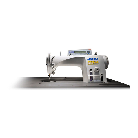
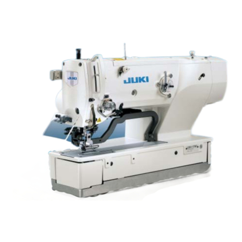
JUKI LH-4500C Series User manual

INSTRUCTION MANUAL
LH-4500C Series / SC-956

i
CONTENTS
1. SPECIFICATIONS........................................................................................................ 1
1-1. Specications of the sewing machine head ...................................................................1
1-2. Specications of the control box ........................................................................................... 1
2. INSTALLATION............................................................................................................ 2
2-1. Drawing of table....................................................................................................................... 2
2-2. Cautions when setting up the sewing machine .............................................................3
2-3. Installation of the sewing machine ........................................................................................ 4
2-4. Installing the thread stand................................................................................................6
2-5. Installing the control box..................................................................................................6
2-5-1. Preparing for installation of the control box ........................................................................ 6
2-5-2. Installing the electrical box.................................................................................................. 7
2-6. Installing the pedal sensor ...............................................................................................7
2-7. Installing the reactor box (Only for the EU type models) ..............................................8
2-8. Connecting the power switch cable ................................................................................8
2-8-1. Installing the power switch.................................................................................................. 8
2-8-2. Connecting the power source cord ..................................................................................... 9
2-9. Installing the accessory ring core (Only for the EU type models)................................9
2-9-1. Installing the accessory ring core supplied with the electrical box...................................... 9
2-10. Connecting the cords ...................................................................................................10
2-11. Handling the cords ........................................................................................................ 11
2-12. Attaching the connecting rod.......................................................................................12
2-13. Adjustment of the pedal................................................................................................12
2-13-1. Installing the connecting rod ........................................................................................... 12
2-13-2. Adjusting the pedal angle................................................................................................ 12
2-14. Pedal operation .............................................................................................................13
2-15. Lubrication.....................................................................................................................14
2-15-1. Supplying oil to the oil tank ............................................................................................. 14
2-15-2. Lubricating the hook race portion .................................................................................. 14
2-16. How to use the operation panel (Basic explanation) .................................................15
2-16-1. Selection of the language (operation to be done at rst) ................................................ 15
2-16-2. Names and functions of the panel keys.......................................................................... 17
2-16-3. Basic operation ............................................................................................................... 19
3. PREPARATION BEFORE SEWING .......................................................................... 20
3-1. Attaching the needle ............................................................................................................. 20
3-2. Attaching and removing the bobbin .................................................................................... 20
3-3. Installing the bobbin .......................................................................................................21
3-4. Threading the machine head ................................................................................................ 22

ii
3-5. Winding the bobbin thread ................................................................................................... 23
3-6. Installing the attachment ...................................................................................................... 25
4. ADJUSTING THE SEWING MACHINE ..................................................................... 26
4-1. Thread tension.................................................................................................................26
4-1-1. Adjusting the tension of thread tension controller No. 1 ................................................... 26
4-1-2. Adjusting the needle thread tension (Active tension)........................................................ 26
4-1-3. Adjusting the bobbin thread tension.................................................................................. 27
4-2. Adjusting the thread take-up spring and the thread take-up stroke ..........................28
4-3. Presser foot (Active presser device) .............................................................................29
4-3-2. Micro-lifter function ........................................................................................................... 29
4-3-1. Presser foot pressure ....................................................................................................... 29
4-3-3. Changing the initial value of the presser foot pressure..................................................... 30
4-3-4. Manual lifting of the presser foot....................................................................................... 30
4-4. Adjusting the stitch length .............................................................................................31
4-5. Changing the sewing speed...........................................................................................31
4-6. LED hand light .................................................................................................................32
4-7. Reverse feed stitching ....................................................................................................33
4-8. Custom switch.................................................................................................................33
4-9. Adjusting the amount of oil (oil splashes) in the hook................................................35
4-9-1. Adjusting the amount of oil in the hook ............................................................................. 35
4-9-2. How to conrm the amount of oil (oil splashes) ................................................................ 36
4-9-3. Sample showing the appropriate amount of oil................................................................. 36
5. HOW TO USE THE OPERATION PANEL ................................................................. 37
5-1. Explanation of the sewing screen (when selecting a sewing pattern).......................37
5-2. Sewing patterns...............................................................................................................41
5-2-1. Sewing pattern conguration ............................................................................................ 41
5-2-2. List of sewing patterns ...................................................................................................... 42
5-2-3. Reverse feed stitching (at start) pattern............................................................................ 44
5-2-4. Reverse feed stitching (at end) pattern............................................................................. 50
5-2-5. Editing the sewing patterns............................................................................................... 51
5-2-6. List of pattern functions..................................................................................................... 55
5-2-7. Teaching function.............................................................................................................. 63
5-2-8. One-touch utility changeover function .............................................................................. 65
5-2-9. Registration of a new sewing pattern................................................................................ 66
5-2-10. Copying a pattern ........................................................................................................... 68
5-2-11. Narrow-down function ..................................................................................................... 69
5-3. Counter function .............................................................................................................71
5-3-1. Displaying the sewing screen under the counter display mode........................................ 71
5-3-2. Types of the counter ......................................................................................................... 71

iii
5-3-3. How to set the counter...................................................................................................... 72
5-3-4. How to reset the count-completion state .......................................................................... 75
5-4. Simplied chart of panel displays .................................................................................76
5-5. List of memory switch data ............................................................................................77
5-6. List of errors ....................................................................................................................83
5-7. Memory switch data ........................................................................................................87
6. MAJOR NEW FUNCTIONS ....................................................................................... 89
6-1. Corner stitching function ...............................................................................................89
6-2. Correcting the needle thread tension according to the remaining amount of thread
wound on the bobbin....................................................................................................93
6-3. Tension correction (with respect to sewing speed)..................................................... 95
6-4. Correcting the presser foot pressure according to the sewing speed ......................97
7. CARE ......................................................................................................................... 99
7-1. Cleaning ...........................................................................................................................99
7-2. Applying grease.............................................................................................................101
7-2-1. Applying grease to the needle bar and thread take-up lever .......................................... 101
7-2-2. Applying grease to the presser bar bushing ................................................................... 103
7-3. Replacing the fuse ........................................................................................................103
7-4. Disposal of batteries .....................................................................................................104
8. ADJUSTMENT OF THE MACHINE HEAD (APPLICATION) .................................. 105
8-1. Needle-to-hook relation ................................................................................................105
8-2. Adjusting the timing between the needle and the blade point of hook....................107
8-3. Adjusting the hook needle guard................................................................................. 110
8-4. Adjusting the bobbin case opening lever ................................................................... 110
8-5. Adjusting the position of counter knife, knife pressure and clamp pressure ......... 111
8-6. Adjusting the thread trimming cam timing ................................................................. 113
8-7. Adjusting the thread clamp device (* excluding the F type model).......................... 114
8-8. Adjusting the height and inclination of the feed dog................................................. 117
8-9. Replacing the gauge ..................................................................................................... 118
8-10. Replacing the bobbin thread slack prevention spring (LH-4588C) ....................... 118
8-11. Stop of the needle bar and the turning angle of corner stitching (LH-4588C-7) ... 119
8-12. Active-presser multi-layered section detection function (* excluding the F type
model) ..........................................................................................................................120
8-12-1. Multi-layered section detection function........................................................................ 120
8-12-2.
Setting the multi-layered portion changeover timing according to the number of stitches
.. 125
8-13. Grease shortage alarm ...............................................................................................127
8-13-1. Regarding the grease shortage alarm .......................................................................... 127
8-13-2. E221 Grease-shortage error......................................................................................... 127
8-13-3. Regarding K118 error resetting procedure ................................................................... 128

iv
9. HOW TO USE THE OPERATION PANEL (APPLICATION).................................... 129
9-1. Management of sewing patterns..................................................................................129
9-1-1. Creation of a new pattern ............................................................................................... 129
9-1-2. Copying a pattern ........................................................................................................... 131
9-1-3. Deleting a pattern ........................................................................................................... 132
9-2. Setting up the polygonal-shape stitching...................................................................133
9-2-1. Editing a polygonal-shape stitching pattern .................................................................... 133
9-2-2. Creating a new polygonal-shape stitching pattern.......................................................... 139
9-2-3. Setting the step from which polygonal-shape stitching is started ................................... 140
9-2-4. How to carry out the corner stitching using a polygonal-shape stitching pattern............ 141
9-3. Cycle pattern..................................................................................................................142
9-3-1. Selecting the cycle pattern.............................................................................................. 142
9-3-2. Editing cycle sewing data ............................................................................................... 143
9-3-3. Creating a new cycle pattern .......................................................................................... 144
9-3-4. Setting the step from which cycle sewing pattern is started ........................................... 146
9-4. Custom patterns............................................................................................................147
9-4-1. Selecting the custom pattern .......................................................................................... 147
9-4-2. Creating a new custom pattern....................................................................................... 149
9-4-3. Editing the custom pattern .............................................................................................. 152
9-4-4. Copying and deleting the custom pattern ....................................................................... 153
9-5. Condensation custom pattern .....................................................................................155
9-5-1. Selecting the condensation custom ................................................................................ 155
9-5-2. Creating a new condensation custom............................................................................. 155
9-5-3. Condensation custom edit function................................................................................. 158
9-5-4. Copying/deleting a condensation custom ....................................................................... 159
9-6. Simple lock of the screen .............................................................................................160
9-7. Version information.......................................................................................................160
9-8. Adjustment of brightness of the LED panel................................................................161
9-9. Information.....................................................................................................................162
9-9-1. Data communication ....................................................................................................... 162
9-9-2. USB ................................................................................................................................ 165
9-9-3. NFC ................................................................................................................................ 166
9-10. Key customization.......................................................................................................167
9-10-1. Assignable data ............................................................................................................ 167
9-10-2. How to assign a function to a key ................................................................................. 168
9-11. Maintenance management function ..........................................................................170
10. QUICK REFERENCE CHART ACCORDING TO STITCH PITCH GAUGE (CON-
VERSION TABLE OF "1 PITCH/MM").................................................................. 174
11. GAUGE PARTS LIST ............................................................................................. 175
12. CAUSES AND CORRECTIVE MEASURES FOR PHENOMENA IN SEWING..... 178
– 1 –
1. SPECIFICATIONS
1-1. Specications of the sewing machine head
Type of machine head Needle thread clamp type
7 1.8-fold capacity hook, without
corner stitching function
N With
0 Without
8 1.8-fold capacity hook, with
corner stitching function
7 With
Without
F 6.4 mm(1/4 inch)
G
For jeans and heavy-weight materials
F
For attaching tape to foundation
LH-45 8C-F B
LH-4578C-FFF0B LH-4578C-FGF7NB LH-4588C-FGF7NB
Max. sewing speed Stitch length 0 to 4.00 :
3,000 sti/min
Stitch length 0 to 5.00 :
3,000 sti/min
Stitch length 5.05 to 7.00 :
2,000 sti/min
Stitch length 0 to 5.00 :
3,000 sti/min
Stitch length 5.05 to 6.00 :
2,500 sti/min
Stitch length 6.05 to 7.00 :
2,000 sti/min
Stitch length 4 mm 7 mm
Presser foot pressure con-
trol Electronic control
Needle *1 DP×5 #9 to #16 DP×5 #16 to #23 DP×5 #16 to #23
Applicable count of thread #80 to #30
#30 to #3
It should be noted, however, applicable counts of thread (for bobbin
thread) are #3 to #8 / #20.
(Thread counts #3 to #5 are supported as option.)
Counts of thread that can be
trimmed #30 to #3
(Thread counts #3 to #5 are supported as option.)
Separately driven needle
bar mechanism
Without With
Motor AC servo motor
Lubricating oil JUKI NEW DEFRIX OIL No. 1 or JUKI CORPORATION GENUINE OIL 7
Number of patterns
Sewing pattern ........................... 99 patterns For the polygonal shape sewing, as many as 10 patterns
can be registered.)
Cycle sewing pattern.................. 9 patterns
Custom-pitch pattern.................. 20 patterns
Condensation custom pattern .... 9 patterns
Noise
-Equivalent continuous emis-
sion sound pressure level (LpA)
at the workstation:
A-weighted value of 79 dBA
; (Includes KpA = 2.5 dBA) ;
according to ISO 10821- C.6.2
-ISO 11204 GR2 at 2,000 sti/
min.
-Equivalent continuous emission sound pressure level (LpA) at the
workstation:
A-weighted value of 79 dBA ; (Includes KpA = 2.5 dBA) ; according
to ISO 10821- C.6.2 -ISO 11204 GR2 at 2,000 sti/min.
-Equivalent continuous emission sound pressure level (LpA) at the
workstation:
A-weighted value of 84 dBA ; (Includes KpA = 2.5 dBA) ; according
to ISO 10821- C.6.2 -ISO 11204 GR2 at 2,800 sti/min.
*1 : Needle used depends on the destination.
1-2. Specications of the control box
Model SC-956B
Single phase 100 to 120V 3-phase 200 to 240V Single phase
220 to 240V
Single phase
220 to 240V CE
Frekans 50Hz/60Hz 50Hz/60Hz 50Hz/60Hz 50Hz/60Hz
Humidity : 90% or less
600VA 600VA 600VA 600VA

– 2 –
2. INSTALLATION
2-1. Drawing of table
A4×ø3.4 on the bottom surface, depth 20
(Drill a hole at the time of set-up.)
BInstalling position of drawer stopper (on the reverse side)
Cø17 drilled hole
D3×ø13 drilled hole
E2×ø3.5, depth 10
F2×ø3.5, depth 10
GThrough hole
H8×ø2.7, depth 6
(Drill a hole at the time of set-up.)
V-V
U-U
Y-Y
Y
Z
Z
Z-Z
X
X
X-X
V
U
U
V
Y
Y
T
T
T-T
Y
90
35
500
42
±
1
268.8
86.5
300
±
1
503.9
±
0.5
308
205
360
84
±
0.5
184.5
90
42
101.5
336
± 0.5
21
23
129
21.5
21
)
(
25
35
91
70
97
19
14.2
14.2
56
52
9
14
60
±
0.5
81.1
810
52.5
34
+0.5
0
14.5
19
30
152
21.5
43
27.5
(249)
50
35
±
0.5
170
75
(15)
195
13.5
+0.5
0
459.5
(
)
47.5
154.5
556.6
+1
-0.5
200
141
55
200
±
1
22.5
R
30
R
10
R
10
R
20
R
2
R
2
R
2
R
2
R
2
R
242.5
R
242.5
R
8
R
8
R
8
R
27.5
R
30
R
30
R
8
R
8
R
10
R
10
R
20.5
R
10
R
10
R
22.5
R
2
R
2
R
2
R
10
R
20.5
R
27.5
R
8
R
20
R
10
R
10
R
10
R
10
R
10
R
10
R
10
R
10
R
10
R
10
R
20
R
20
R
30
R
23.5
50
1200
170
13.5
+0.5
0
20.5
±
0.5
193
2
20
+0.5
0
100
50
80 80
235
13
18
15.5
+0.5
0
75
40
(
)
21
+0.5
0
50
200
29
±
0.5
29
±
0.5
40
535
22.5
35
128
375
40
±
40
±
3.3
A
B
H
C
G
D
E
F
(Two
locations)
(Two
locations)
(Two
locations)

– 3 –
2-2. Cautions when setting up the sewing machine
Thank you very much for the purchase of JUKI Industrial Sewing Machine this time. Make sure of items
2-1 through 2-16 before operating to use this sewing machine with ease.
[How to carry the sewing machine]
Carry the sewing machine while holding the ma-
[Caution when placing the sewing machine]
Place the sewing machine on a horizontal and
plane place when placing it and do not place any
protruding thing such as a screwdriver or the like.
1. Never hold the handwheel since it
rotates.
2. Be sure to handle the sewing ma-
chine with two persons or more
since the sewing machine weighs
55 kg or more.

– 4 –
2-3. Installation of the sewing machine
Sheet B
❹
25 mm
❺
19 mm
Sheet A
❷
❹
❸
❸
❺❺
❻
❼
❶
❽
1) Attaching the hinge seats and the support
rubbers of the machine head
Fix accessory hinge seat ❶supplied with
the unit on the table with wood screw ❼
and washer ❽while placing sheet plate ❻
between the hinge seat and the table as
Fix machine head support rubbers ❷and
❸on the table with nails while putting
sheets A(standard: 3 pieces) and sheet
B(standard: 1 piece) under the machine
head support rubbers.
Use nail ❺for sheet Band nail ❹for
sheets A.
support rubbers ❸; i.e., the rubber for the
right and that for the left. Be sure to check
the types of the support rubbers before
Sheet A (eight pieces) and sheet B (four pieces) are supplied with the machine as acces-
sories.
For the sheet A, three sheets are to be used as standard for each mounting position. For
the sheet B, one sheet is to be used as standard. (The state shown in the left gure) The
sheets A and B are used for adjusting the height of the top surface of the bed. Use one
more sheet to increase the height, or use only one sheet to decrease it.
Be sure to use a short nail ❺ for sheet B. If long nail ❹ is used, the nail tip can penetrate
the table giving rise to a risk of injury.
2) Attaching the oil pan
Fix the oil pan ❾supplied with the machine
on the table by tightening ten wood screws.
Operator’s side Table
❾
Align
Align

– 5 –
3) Installing the oil bottle
Put oil seal over accessory oil remover
and secure them with screw and nut .
At this time, placing a washer be-
tween two packing washers , at-
tach them to the screw. Then, tighten
screw together with washer ,
spring washer and nut as shown
in the gure on the left. (At three loca-
tions)
Put oil bottle into oil remover by hand.
4) Install hinge on the bed with screw .
Engage the hinge with the rubber hinge of the
table. Then, place the machine head on the
machine head support rubber.
C
5) Detach air vent cap from the bed.
1. If the sewing machine runs without
removing air vent cap , oil may
leak from feed box unit C.
2. In the case of transporting the sew-
ing machine with its head detached
from the table, it is necessary to
attach air vent cap to the bed.
6) Securely install machine head support bar
to the table until its rib portion is pressed
against the table.
If it is inevitable to carry out work
with the machine head support bar
removed for the purpose of mainte-
nance or repair, such a work must be
carried out by two or more workers.
In addition, if the machine head is
tilted more than necessary, oil may
leak from the oil tank or oil inlet. To
prevent the oil leakage, be sure to
remove oil before tilting the machine
head.

– 6 –
2-4. Installing the thread stand
Assemble the thread stand, set it up on the ma-
chine table using the installation hole in the table
and tighten nut ❶gently.
When you use power supplied by the overhead
power line, pass the power supply cord through
hollow spool rest rod ❷.
❷
❶
300 mm from the top
surface of table
2-5. Installing the control box
0.8 mm
❷
❸❹
❺
❻
❶
1) Secure toothed washer ❷and vibration-proof rubber ❸to control box ❶. (At four locations)
* Tighten the toothed washer until it protrudes the control box surface by 0.8 mm.
2) Secure control box mounting plate ❹to the control box with plain washers ❺and nuts ❻. (At
four locations)
2-5-1. Preparing for installation of the control box

– 7 –
2-5-2. Installing the electrical box
❶
❷❷
a
a
❶
❷
Install electrical box ❶
accessory bolts ❷, which are supplied with the
electrical box, in holes ain the table.
Secure pedal sensor ❶to the table with two plain
washers and two wood screws ❷both of which
are supplied with the electrical box.
2-6. Installing the pedal sensor

– 8 –
1) Attach the terminals of power cord ❶coming
from the electrical box to reactor box PCB
asm. ❷and reactor box mounting plate ❸.
Connect brown wire A
and blue wire Bto the third connector respec-
tively from the top of terminal block on the
reactor box PCB asm. using screws. Connect
green/yellow wire Cto reactor box mounting
plate ❸with earth setscrew ❹.
2) Attach cable clip ❺to the power cord com-
ing from the electrical box. Then, attach the
power cord together with the cable clip to
reactor box mounting plate ❸with cable clip
setscrew ❻.
3) Attach cord bushes ❽to input/output cables
❶and ❼of the reactor box. Attach both
bushes in the same manner.
4) Attach reactor box cover to reactor box
mounting plate ❸with four reactor-box cover
setscrews ❾.
❽attached to
input/output cables ❶and ❼in the concave
section on reactor box cover to eliminate a
gap between reactor box and cover .
5) Secure reactor box to the undersurface of
table with four accessory wood screws .
6) Secure two cables coming from reactor
box to the table with accessory cable clip
and wood screw .
❼
❽
❽
❶
❾
❽
❸
❸
❶
❷❹
A
B
❻
❺
C
❾
2-7. Installing the reactor box (Only for the EU type models)
2-8. Connecting the power switch cable
Fix power switch ❶under the machine table with
wood screws ❷.
Fix the cable with staples ❸supplied with the ma-
chine as accessories in accordance with the forms
of use.
2-8-1. Installing the power switch
❶
❷
❸
Electrical box
(EU type models:
Reactor box)

– 9 –
Power indication tag
(For example : In the case of 200V)
2-8-2. Connecting the power source cord
• Connecting 3-phase 200 to 240V
• Connecting single phase 100 to 120V
AC200 to 240V
Green/Yellow — GND
White
Black
Red
Power switch
Table
Never use under the wrong voltage and phase.
Rating plate
• Connecting single phase 220 to 240V
Green/Yellow — GND
AC220 to 240V
Light blue
Green/Yellow
Table
Control box
Power switch
Plug
Brown White
Black
White
Black
Red
Table
Power switch
2-9. Installing the accessory ring core (Only for the EU type models)
2-9-1. Installing the accessory ring core supplied with the electrical box
Refer to accessory manual for "Installing the accessory ring core" supplied with the electrical box for
how to install the ring core.
After screwing the cable to
the power switch, bind the
cable sheath portion with
an accessory clip band
inside the power switch.
Green/Yellow
White
White
White
White
Black Black
Black Black
Red Red
Green/Yellow
Control box
Green/Yellow
Control box
Green/Yellow
Green/Yellow

– 10 –
DANGER :
1. To prevent personal injuries caused by electric shock hazards or abrupt start of the sewing ma-
chine, carry out the work after turning OFF the power switch and a lapse of 5 minutes or more.
2. To prevent accidents caused by unaccustomed work or electric shock, request the electric expert
or engineer of our dealers when adjusting the electrical components.
1) Secure pedal sensor ❶on the table using accessory
plain washers and wood screws ❷(two each) supplied
with the control box.
2) Connect the respective cords to the corresponding con-
nectors of CTL PCB, PWR PCB and SUB-D PCB. (Fig.
1)
3) Fix the ground wire ❹on position Aof the control box
with a screw. (Fig. 2)
❷❶
Take care not to incorrectly connect the connec-
tors CN21.
CN32
CN30
CN36
CN38
CN21
CN37
CN20
40P
9P
6P
18P
4P
4P
15P
White
White
White
White
White
White
Brown
PWR PWB
CTL PWB
3P White
CN34
2-10. Connecting the cords
Fig. 1
Fig. 2
❹
A
❸
CN37 CN36
CN30
CN38 CN32 CN20 CN21

– 11 –
2-11. Handling the cords
➡
A
❷❶
❹
❸
1) Bring the cords under the table into the con-
trol box.
2) Put the cord brought into the control box
through cord exit plate ❶
band ❷.
3) Install control box cover ❸with four set-
screws ❹.
Arrange the cord so that it is not
tensed or hitched even when the ma-
chine head is tilted. (See A section.)
For the purpose of preventing the
cord breakage, take care not to allow
the cords to be caught between the
control box and control box cover ❸
when attaching the latter.
DANGER :
1. To prevent personal injuries caused by electric shock hazards or abrupt start of the sewing ma-
chine, carry out the work after turning OFF the power switch and a lapse of 5 minutes or more.
2. To prevent accidents caused by unaccustomed work or electric shock, request the electric expert
or engineer of our dealers when adjusting the electrical components.

– 12 –
❹
❺
❷
B
❸
A
❶
1. If the screw is excessively loos-
ened, the spring will come o.
Loosen the screw to such an extent
that the top of the screw can be
observed from the case.
2. Whenever you have adjusted the
screw, be sure to secure the screw
by tightening metal nut ❺ to pre-
vent the screw from loosening.
1) Fix connecting rod ❶to installing hole Bof
pedal lever ❷with nut ❸.
2) Installing connecting rod ❶to installing hole
Awill lengthen the pedal depressing stroke,
and the pedal operation at a medium speed
will be easier.
3) The pressure increases as you turn reverse
depressing regulator screw ❹in, and de-
creases as you turn the screw out.
2-12. Attaching the connecting rod
2-13. Adjustment of the pedal
❷❹
❷
❶
❸
2-13-1. Installing the connecting rod
2-13-2. Adjusting the pedal angle
Move pedal ❸to the right or left as illustrated by
the arrows so that motor control lever ❶and con-
necting rod ❷are straightened.
1) The pedal tilt can be freely adjusted by
changing the length of the connecting rod ❷.
2) Loosen adjust screw ❹, and adjust the
length of connecting rod ❷.
WARNING :
To protect against possible personal injury due to abrupt start of the machine, be sure to start the
following work after turning the power o and a lapse of 5 minutes or more.
WARNING :
Turn OFF the power before starting the work so as to prevent accidents caused by abrupt start of
the sewing machine.

– 13 –
2-14. Pedal operation
A
B
C
D
E
1)
The machine runs at low sewing speed when
you lightly depress the front part of the pedal. B
2) The machine runs at high sewing speed when
you further depress the front part of the pedal.
A(If the automatic reverse feed stitching has
been preset, the machine runs at high speed
after it completes reverse feed stitching.)
3) The machine stops (with its needle up or
down) when you reset the pedal to its original
position. C
4) Presser lifting operation Dis performed by
lightly depressing the back part of pedal.
5) Thread trimming Eis performed by further
depressing the back part of pedal.
・
When starting sewing from the state that the
presser foot has been lifted with the Auto-lifter
and you depress the back part of the pedal,
the presser foot only comes down.
・
If you reset the pedal to its neutral position
during the automatic reverse feed stitching at
seam start, the machine stops after it com-
pletes the reverse feed stitching.
・
The machine will perform normal thread trim-
ming even if you depress the back part of the
pedal immediately following high or low speed
sewing.
・
The machine will completely perform thread
trimming even if you reset the pedal to its
neutral position immediately after the ma-
chine started thread trimming action.

– 14 –
2-15. Lubrication
Pour oil for lubricating the hook into the oil tank
before putting the sewing machine into use.
1) Remove oil inlet cap ❶. Pour JUKI New De-
frix Oil No. 1 (part number: MDFRX1600C0)
or JUKI CORPORATION GENUINE OIL 7
(part number: 40102087) into the oil tank
using the accessory oiler.
1. When using a new sewing machine for the rst time or using the sewing machine which
has not been used for a long time, run in the sewing machine at a sewing speed of 1,000
sti/min or less and check the oil quantity in the hook before use.
2. For the oil for hook lubrication, purchase JUKI NEW DEFRIX OIL No. 1 (Part No. : MD-
FRX1600C0) or JUKI MACHINE OIL #7 (Part No. : MML007600CA).
3. Be sure to lubricate clean oil.
4. Do not operate the sewing machine with oil inlet cap ❶ left detached. Do not detach oil
inlet cap ❶ except for feeding oil. Also be careful not to lose the oil inlet cap.
5. Oil amount mark ❷ changes its color to three dierent colors.
Red: Oil amount is insucient / White: Normal range / Green: Full
Hook race portion
2-15-1. Supplying oil to the oil tank
2-15-2. Lubricating the hook race portion
2) Supply the oil until oil amount mark ❷
at the upper right on the operation pan-
el turns green.
Be aware that, if an excessive amount
of oil is put in the oil tank, oil may leak
from the air vent of the oil tank, or
adequate lubrication may not be per-
formed. In addition, be aware that the
swiftly poured into the oil tank.
3) Add oil to the oil tank when oil amount
mark ❷at the upper right on the op-
eration panel turns red while you are
operating the sewing machine.
Lubricate the race portions of the hooks (right and
left) of a new sewing machine or after leaving the
sewing machine unused for a long time, with a
few drops of oil.
❶
WARNING :
1. Do not connect the power plug until the lubrication has been completed so as to prevent acci-
dents due to abrupt start of the sewing machine.
2. To prevent the occurrence of an inammation or rash, immediately wash the related portions if oil
adheres to your eyes or other parts of your body.
3. If oil is mistakenly swallowed, diarrhea or vomitting may occur. Put oil in a place where children
cannot reach.
Hook race portion
❷

– 15 –
2-16. How to use the operation panel (Basic explanation)
2-16-1. Selection of the language (operation to be done at rst)
Select the language to be displayed on the operation panel when you turn ON the power to your sewing
language, the language selection screen will be displayed every time you turn ON the power to the sew-
ing machine.
① Turning ON the power switch
Be aware that the needle bar may move automatically, according to the settings of the
sewing machine, when the power is turned ON.
<Welcome screen>
Firstly, the welcome screen is displayed
on the panel. Then, the language selection
screen is displayed.
② Selecting the language
<Language selection screen>
❷❶
Select the language you want to use and
press corresponding language button ❶.
Then, press ❷. This determines the
language to be displayed on the panel.
The language to be displayed on the operation panel can be changed using the memory switch U406.
Refer to "5-5. List of memory switch data" p.77 for details.
This manual suits for next models
4
Table of contents
Other JUKI Sewing Machine manuals

JUKI
JUKI LZH-1290 User manual

JUKI
JUKI MF-7500 Series User manual

JUKI
JUKI TL-2010Q User manual

JUKI
JUKI LK-1900A Quick start guide

JUKI
JUKI HZL-T100 User manual

JUKI
JUKI NZ-120 User manual

JUKI
JUKI ASN-690 User manual

JUKI
JUKI LK1903B/BSS302 User manual

JUKI
JUKI AMS-210EN/IP-420 User manual

JUKI
JUKI UT55 User manual

JUKI
JUKI MEB-3200 Series Quick start guide

JUKI
JUKI DDL-555-4 User manual

JUKI
JUKI HZL-E71 User manual

JUKI
JUKI TSC-441 User manual

JUKI
JUKI AMS-210EN/IP-420 User manual

JUKI
JUKI MO-1000 User manual

JUKI
JUKI LU-2210N-7 User manual

JUKI
JUKI CP-160 User manual

JUKI
JUKI DNU-1541-7 User manual

JUKI
JUKI LK-1900B series User manual