JUKI DDL-9000B User manual

ENGLISH
DDL-9000B
INSTRUCTION MANUAL

CONTENTS
SPECIFICATIONS ................................................................................................................................1
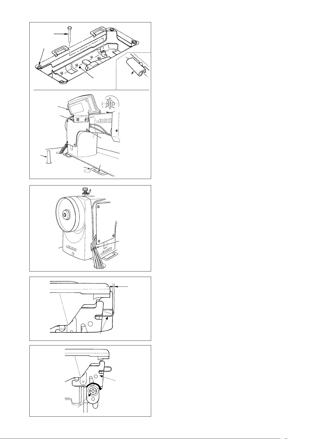
1. INSTALLATION............................................................................................................................2
2. ADJUSTING THE HEIGHT OF THE KNEE LIFTER ....................................................................4
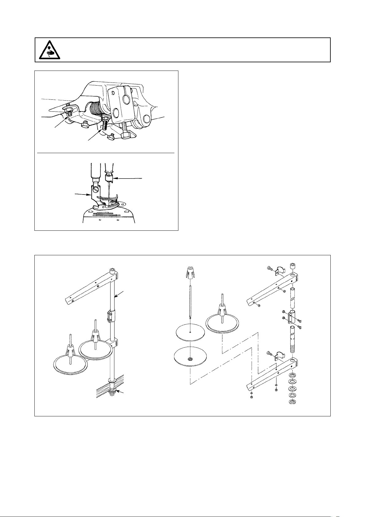
3. INSTALLING THE THREAD STAND............................................................................................4
4. LUBRICATION (DDL-9000B-S , -M ).....................................................................................5
5. ATTACHING THE NEEDLE ..........................................................................................................6
6.
SETTING THE BOBBIN INTO THE BOBBIN CASE .......................................................................... 6
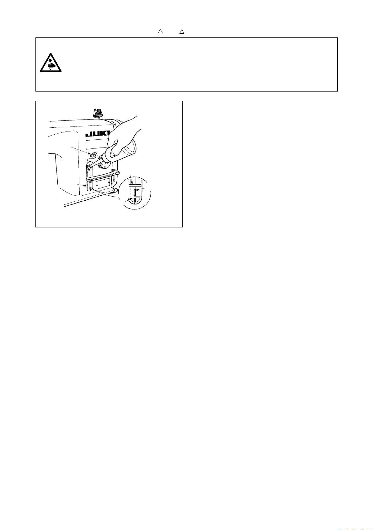
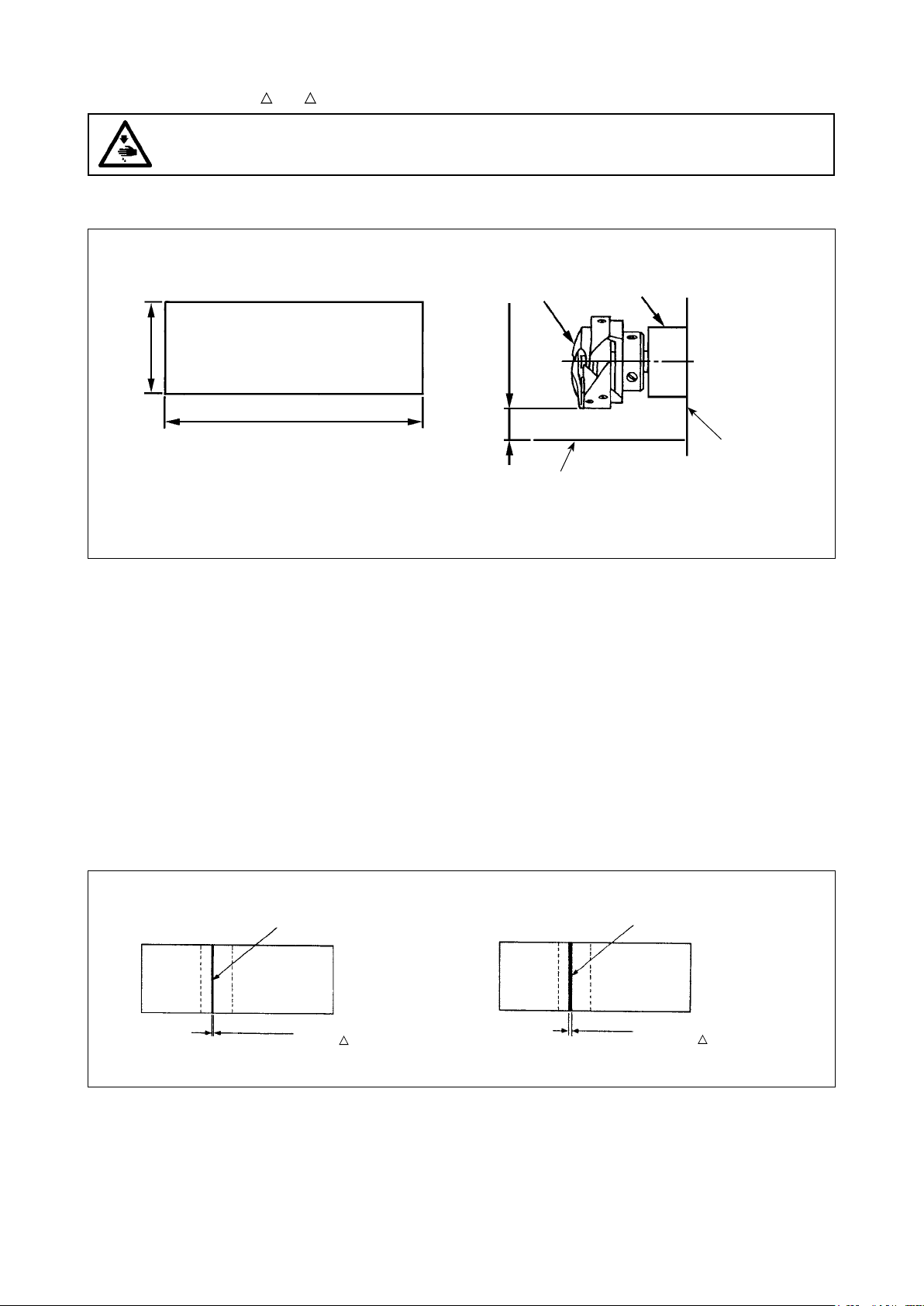
7. ADJUSTING THE AMOUNT OF OIL (OIL SPLASHES) IN THE HOOK(DDL-9000B-S , -M ) .7
(1) How to conrm the amount of oil (oil splashes) ...................................................................................... 7
(2) Sample showing the appropriate amount of oil....................................................................................... 7
8. ADJUSTING THE AMOUNT OF OIL IN THE HOOK (DDL-9000B-S , -M )..............................8
9. THREADING THE MACHINE HEAD............................................................................................9
10. THREAD TENSION.......................................................................................................................9
(1) Adjusting the needle thread tension........................................................................................................ 9
(2) Adjusting the bobbin thread tension ....................................................................................................... 9
11. WINDING THE BOBBIN THREAD .............................................................................................10
12. PRESSER FOOT PRESSURE....................................................................................................11
13.
ADJUSTING THE STITCH LENGTH............................................................................................. 11
14.
ADJUSTING THE THREAD TAKE-UP SPRING AND THE THREAD TAKE-UP STROKE.................. 12
15. ADJUSTING THE NEEDLE STOP POSITION ...........................................................................13
(1) Stop position after thread trimming ....................................................................................................... 13
(2) Adjusting procedure of the needle up/down stop position..................................................................... 13
16. PEDAL PRESSURE AND PEDAL STROKE..............................................................................14
(1) Adjusting the pressure required to depress the front part of the pedal ................................................. 14
(2) Adjusting the pressure required to depress the back part of the pedal ................................................ 14
(3) Adjusting the pedal stroke .................................................................................................................... 14
17. ADJUSTMENT OF THE PEDAL.................................................................................................14
(1) Installing the connecting rod ................................................................................................................. 14
(2) Adjusting the pedal angle...................................................................................................................... 14
18. PEDAL OPERATION ..................................................................................................................15
19. NEEDLE-TO-HOOK RELATIONSHIP ........................................................................................16
20. ONE-TOUCH TYPE REVERSE FEED STITCHING MECHANISM............................................17
21. ADJUSTING THE POSITION OF THE WIPER (DDL-9000B- -WB, -0B) ............................18
22. CUNTER KNIFE..........................................................................................................................19
23. HEIGHT AND TILT OF THE FEED DOG ....................................................................................20
(1) Standard value of the height of the feed dog ........................................................................................ 20
(2) Adjusting the height and tilt of the feed dog .......................................................................................... 20
24. ADJUSTING THE FEED TIMING ...............................................................................................21
25. THREAD TENSION RELEASE RELEASING MECHANISM .....................................................21
26. MICRO-LIFTING MECHANISM OF THE PRESSER FOOT.......................................................22
27. SEWING CONDENSED STITCHES ...........................................................................................23
28. FEED CONVERSION SPRING MECHANISM (DDL-9000B-S , -M )...................................23
29. CARE ..........................................................................................................................................24
(1) Conrmation of the amount of oil in the hook oil tank. .......................................................................... 24
(2) Cleaning ............................................................................................................................................... 24
i

S : Micro-quantity lubrication
M : Semi-dry
D : Dry
DDL-9000B- S :
Medium-weight materials
H : Heavy-weight materials
A : Light weight materials
SPECIFICATIONS
-SH -MA*3
4,500 sti/min 5,000 sti/min
Thread trimming
speed 500 sti/min (100 to 500sti/min)
Stitch length 5mm *1 4mm
Presser foot lift
(by knee lifter) 10 mm (standard) 15 mm (max.)
Needle *2
1738 Nm65 to 110
(DB×1 #9 to 18)
1738 Nm125 to 160
(DB×1 #20 to 23)
1738 SAN10 Nm60 to 75
(DB×1 SF#8 to 11)
134 Nm65 to 110
(DP×5 #9 to 18)
134 Nm125 to 160
(DP×5 #20 to 23)
134 Nm60 to 75
(DP×5 #8 to 11)
Lubricating oil JUKI NEW DEFRIX OIL No. 1
or JUKI MACHINE OIL #7
- JUKI NEW DEFRIX OIL No. 1
or JUKI MACHINE OIL #7
SS, MS, MA ;
'- Equivalent continuous emission sound pressure level (LpA) at the workstation:
2.5 dBA) ; according to ISO 10821- C.6.2 -ISO
'- Equivalent continuous emission sound pressure level (LpA) at the workstation:
2.5 dBA) ; according to ISO 10821- C.6.2 -ISO
'- Equivalent continuous emission sound pressure level (LpA) at the workstation:
2.5 dBA) ; according to ISO 10821- C.6.2 -ISO
-SS -MS -DS
Max. sewing 5,000sti/min 4,000 sti/min
speed
A-weighted value of 77 dBA ; (Includes KpA =
11204 GR2 at 4,000 sti/min.
SH ;
Noise A-weighted value of 77 dBA ; (Includes KpA =
11204 GR2 at 4,000 sti/min.
DS ;
A-weighted value of 79 dBA ; (Includes KpA =
11204 GR2 at 4,000 sti/min.
• The sewing speed will vary depending on the sewing conditions. The sewing speed preset at the time of shipping is 4,000sti/
min. The thread trimming speed can be changed within the range of ( ). The thread trimming speed preset at the time of
shipping is 500sti/min.
*1 : When stitch length exceeds 4 mm or more, set the max. sewing speed to 4,000 sti/min or less for use.
*2 : Needle used depends on the destination.
*3 : MA type is for light-weight materials. In the case the sewing machine is used with its speed of stitch set at 4,000 sti/min
or higher, the presser regulating spring and thread tension spring should be changed with S type ones.
– 1 –

1. INSTALLATION
1) Carry the sewing machine with two persons as
shown in the gure above.
(Caution) Do not hold the handwheel.
23.5 mm 19.5 mm
1
2
4
3
A B
11
3
3
8
2) Do not put protruding articles such as the screw-
driver and the like at the location where the sew-
ing machine is placed.
3) The under cover should rest on the four cor-4) Fix two rubber seats 1 on side A (operator’s
ners of the machine table groove. Mount rubber side) using nails 2 as illustrated above. Fix two
hinge seat 8 on the table and x it on the table cushion seats 3on side B (hinged side) using a
with a nail. rubber-based adhesive. Then place under cover
4 on the xed seats.
5
C
5) Remove air vent cap 5 attached to the machine
bed.
(Caution)
1. If the sewing machine is operated without re-
moving air vent cap 5, oil leakage from gear
box portion C may occur.
2. Be sure to attach cap 5when transport-
ing the machine head in the state that the
machine head is removed from the machine
table.
– 2 –

6) Fit knee lifter pressing rod 6. Fit hinge 7into
9
7
6
4
the opening in the machine bed, and t the
machine head to table rubber hinge 8 before
placing the machine head on cushions 9 on the
four corners.
7) Securely attach head support rod !0 to the table
until it goes no further. Regarding the control
panel !1, remove two side plate xing screws
!2, place the rubber packing !3, which is one of
the accessories of the control panel !1, between
the head section and control panel !1, then x
them together.
(Caution)
1. Do not use the screws supplied as accesso-
ries of control panel !1.
2.
Be sure to mount the machine head support
bar on the machine table so that its height
from the table surface becomes 55 to 60 mm.
For the sewing machine provided with the AK
device, be sure to mount the support bar on
the table so that its height from the table sur-
face becomes 38 to 43 mm.
8) Bundle cable clip band !4 supplied as accesso-
ries of the machine head at the root of the cable.
!0
!1
!2 !2
!1
!3
!2
7
8
!4
2.0 to 3.5 mm
!7
!6
!5
9) Check to be sure that the table and the safety
switch arm !5 are engaged with each other by 2.0
mm to 3.5 mm, with the sewing machine slightly
tilted.
(Caution) If the engagement between the table and
the safety switch arm is 2 mm or less, Error
302 may occur at the time of startup. Or, if the
aforementioned engagement is 3.5 mm or more,
safety switch arm !5 may break.
10) If the engagement between the table and safety
switch arm !5 is outside the range of 2.0 mm
and 3.5 mm, loosen safety switch mounting
screw !6 and tilt safety switch !7 in the direction
of the arrow to adjust the engagement of safety
switch arm !5 with the table.
– 3 –

2. ADJUSTING THE HEIGHT OF THE KNEE LIFTER
WARNING :
Turn OFF the power before starting the work so as to prevent accidents caused by abrupt start of
the sewing machine.
1
4
3
2
The standard height of the presser foot lifted using
the knee lifter is 10 mm.
You can adjust the presser foot lift up to 15 mm us-
ing knee lifter adjust screw 1.
(Caution)
1. Do not operate the sewing machine in the
state that the presser foot 3is lifted by 10
mm or more since the needle bar 2comes in
contact with the presser foot 3.
2. Knee lifter initial position
If the adjustment screw 4is over tightened,
the sewing machine will operate in a state
where the presser foot is lifted up, causing
defective sewing or noise.
3. INSTALLING THE THREAD STAND
2
1
1) Assemble the thread stand unit, and insert it in the hole in the machine table.
2) Tighten nut 1.
3) For ceiling wiring, pass the power cord through spool rest rod 2.
– 4 –

4. LUBRICATION (DDL-9000B-S , -M )
WARNING :
1. Do not connect the power plug until the lubrication has been completed so as to prevent
accidents due to abrupt start of the sewing machine,
2. To prevent the occurrence of an inammation or rash, immediately wash the related portions if oil
adheres to your eyes or other parts of your body.
3. If oil is mistakenly swallowed, diarrhea or vomitting may occur. Put oil in a place where children
cannot reach.
Upper
engraved
marker line
marker line
1
2
3
Upper
engraved
Fill the oil tank with oil for hook lubrication before op-
erating the sewing machine.
1) Remove oil hole cap
1
and ll the oil tank with
JUKI NEW DEFRIX OIL No.1 (Part No. : MD-
FRX1600C0) or JUKI MACHINE OIL #7 (Part
No. : MML007600CA) using the oiler supplied
with the machine.
2) Fill the oil tank with the oil until the top end of
oil amount indicating rod
3
comes between the
upper engraved marker line A and the lower
engraved marker B line of oil amount indicating
window
2
.
If the oil is lled excessively, it will leak from the
air vent hole in the oil tank or proper lubrication
will be not performed. In addition, when the oil
is vigorously lled, it may overow from the oil
hole. So, be careful.
3) When you operate the sewing machine, rell oil if the top end of oil amount indicating rod
3
comes down
to the lower engraved marker line of oil amount indicating window
2
.
(Caution)
1. When you use a new sewing machine or a sewing machine after an extended period of disuse, use
the sewing machine after performing break-in at 2,000 sti/min or less.
2. For the oil for hook lubrication, purchase JUKI NEW DEFRIX OIL No. 1 (Part No. : MDFRX1600C0) or
JUKI MACHINE OIL #7 (Part No. : MML007600CA).
3. Be sure to lubricate clean oil.
4. Do not operate the machine with the oil hole cap
1
removed. Never remove cap
1
from the oil inlet
in any case other than oiling. In addition, take care not to lose it.
– 5 –

5. ATTACHING THE NEEDLE
WARNING :
Turn OFF the power before starting the work so as to prevent accidents caused by abrupt start of
the sewing machine.
Use the specied needle for the machine. Use the
proper needle in accordance with the thickness of
thread used and the kinds of the materials.
1) Turn the handwheel until the needle bar reaches
the highest point of its stroke.
2) Loosen screw 2, and hold needle 1 with its
indented part A facing exactly to the right in
direction B.
3) Insert the needle fully into the hole in the needle
bar in the direction of the arrow until the end of
hole is reached.
4) Securely tighten screw 2.
5) Check that long groove C of the needle is facing exactly to the left in direction D.
(Caution) When polyester lament thread is used, if the indented part of the needle is tilted toward opera-
tor's side, the loop of thread becomes unstable. As a result, hangnail of thread or thread breakage may
occur. For the thread that such phenomenon is likely to occur, it is effective to attach the needle with its
indented part slightly slanting on the rear side.
6.
SETTING THE BOBBIN INTO THE BOBBIN CASE
1) Install the bobbin in the bobbin case so that the
thread wound direction is clockwise.
2) Pass the thread through thread slit A, and
pull the thread in direction C. By so doing, the
thread will pass under the tension spring and
come out from notch B.
3) Check that the bobbin rotates in the direction of
the arrow when thread is pulled.
1
2
C
DB
A
A
B
C
– 6 –

7. ADJUSTING THE AMOUNT OF OIL (OIL SPLASHES) IN THE HOOK
(DDL-9000B-S , -M )
WARNING :
Be extremely careful about the operation of the machine since the amount of oil has to be checked
by turning the hook at a high speed.
(1) How to conrm the amount of oil (oil splashes)
1 Amount of oil (oil splashes) conrmation paper 2 Position to conrm the amount of oil (oil splashes)
Oil splashes conrmation paper
* Place the amount of oil (oil splashes) confirmation paper
under the hook and keep it from the hook by 3 to 10 mm to
conrm the amount.
* When carrying out the procedure described below in 2), conrm the state that the needle thread
from the thread take-up lever to the needle and the bobbin thread are removed, the presser foot
is lifted and the slide plate is removed. At this time, take extreme caution not to allow your n-
gers to come in contact with the hook.
1) If the machine has not been sufciently warmed up for operation, make the machine run idle for approxi-
mately three minutes. (Moderate intermittent operation)
2) Place the amount of oil (oil splashes) conrmation paper under the hook while the sewing machine is in
operation.
3) Conrm that oil exists in the oil tank.
4) Conrmation of the amount of oil should be completed in ve seconds. (Check the period of time with a
watch.)
(2) Sample showing the appropriate amount of oil
Closely fit the
paper against the
wall su rface of
the bed.
Hook Hook driving shaft front bushing
Bed
* Use any paper available regardless of the material.
Approx. 70 mm
Approx. 25 mm
Appropriate amount of oil (small) Appropriate amount of oil (large)
Splashes of oil from the hook
• DDL-9000B-SS, -M
Splashes of oil from the hook
: 1 to 1.5 mm
• DDL-9000B-SS, -M : 0.5 to 1 mm
• DDL-9000B-SH : 1 to 3 mm • DDL-9000B-SH : 2 to 4 mm
1)
2)
The state given in the gure above shows the appropriate amount of oil (oil splashes). It is necessary to nely ad-
just the amount of oil in accordance with the sewing processes. However, do not excessively increase/decrease
the amount of oil in the hook. (If the amount of oil is too small, the hook will be seized (the hook will be hot). If the
amount of oil is too much, the sewing product may be stained with oil.)
Check the oil amount (oil splashes) three times (on the three sheets of paper), and adjust so that it
should not change.
– 7 –

8. ADJUSTING THE AMOUNT OF OIL IN THE HOOK (DDL-9000B-S , -M )
WARNING :
Turn OFF the power before starting the work so as to prevent accidents caused by abrupt start of
the sewing machine.
1
2
4
3
Decrease Increase
Tighten (turn clockwise) oil amount adjustment screw 1to increase the amount of oil in the hook, or loosen
(turn counterclockwise) to decrease it.
(Caution)
[When using RP hook (hook for dry head) for S or -M type]
1. Remove hook driving shaft oil wick setscrew 2and attach hook driving shaft stopper screw 3(Part
No. : 11079506) and rubber ring 4(Part No. : R0036080200).
2. Loosen oil amount adjustment screw 1up to the minimum so as to reduce the oil amount in the
hook. However, do not completely stop the oil and be careful not to allow oil adjustment screw 1to
come off.
3. Never drain the oil in the oil tank even when RP hook (hook for dry head) is used.
– 8 –

9. THREADING THE MACHINE HEAD
1
2
5
4
3
6
7
8
9
!0
!1
!2
!3
A
(Note) Do not pass
this thread
through
section A.
WARNING :
Turn OFF the power before starting the work so as to prevent accidents caused by abrupt start of
the sewing machine.
10. THREAD TENSION
1
2
A
B
3
E F
C
D
(1) Adjusting the needle thread tension (2) Adjusting the bobbin thread tension
1) Turn thread tension No. 1 nut 1 clockwise (in
1)
Turn tension adjusting screw
3
clockwise
(in
direction
A
), to shorten the thread length re-
direction
E
)
to increase or counterclockwise
(in
maining on the needle after thread trimming or
direction
F
)
to reduce the bobbin thread tension.
counterclockwise (in direction
B
), to lengthen
the thread length.
2)
Turn thread tension nut 2 clockwise
(in direction
C
)
to increase or counterclockwise (in direction
D
) to reduce the needle thread tension.
– 9 –

11. WINDING THE BOBBIN THREAD
D
E
B
3
1
6
7
6
5
6
A
C
8
4
2
1) Insert the bobbin deep into the bobbin winder
spindle 1 until it will go no further.
2) Pass the bobbin thread pulled out from the
spool rested on the right side of the thread stand
following the order as shown in the gure on the
left. Then, wind clockwise the end of the bobbin
thread on the bobbin several times.
(In case of the aluminum bobbin, after winding
clockwise the end of the bobbin thread, wind
counterclockwise the thread coming from the
bobbin thread tension several times to wind the
bobbin thread with ease.)
3) Press the bobbin winder trip latch 2 in the
direction of A and start the sewing machine.
The bobbin rotates in the direction of C and the
bobbin thread is wound up. The bobbin winder
spindle 1 automatically as soon as the winding
is nished.
4) Remove the bobbin and cut the bobbin thread
with the thread cut retainer 3.
5) When adjusting the winding amount of the bob-
bin thread, loosen setscrew 4 and move bobbin
winding lever 2 to the direction of A or B. Then
tighten setscrew 4.
To the direction of A : Decrease
To the direction of B : Increase
6) In case that the bobbin thread is not wound evenly on the bobbin, remove the handwheel, loosen screw
5 and adjust the height of bobbin thread tension 8.
• It is the standard that the center of the bobbin is as high as the center of thread tension disk 6.
• Adjust the position of thread tension disk 6 to the direction of D when the winding amount of the bobbin
thread on the lower part of the bobbin is excessive and to the direction E when the winding amount of
the bobbin thread on the upper part of the bobbin is excessive.
After the adjustment, tighten screw 5.
7) To adjust the tension of the bobbin winder, turn the thread tension nut 7.
(Caution)
1. When winding the bobbin thread, start the winding in the state that the thread between the bobbin
and thread tension disk 6is tense.
2. When winding the bobbin thread in the state that sewing is not performed, remove the needle thread
from the thread path of thread take-up and remove the bobbin from the hook.
3.There is the possibility that the thread pulled out from the thread stand is loosened due to the inu-
ence (direction) of the wind and may be entangled in the handwheel. Be careful of the direction of
the wind.
– 10 –

12. PRESSER FOOT PRESSURE
WARNING :
Turn OFF the power before starting the work so as to prevent accidents caused by abrupt start of
the sewing machine.
C
A
B
1
2
1) Loosen nut 2. As you turn presser spring regu-
lator 1 clockwise (in direction A), the presser
foot pressure will be increased.
2) As you turn the presser spring regulator counter-
clockwise (in direction B), the pressure will be
decreased.
3) After adjustment, tighten nut 2.
The standard value of the addition Cof the height of
presser spring regulator is as follows :
• S type : 31.5 to 29 mm (Approximately 40 to
45N/4 to 4.5kg)
• H type : 31.5 to 28 mm (Approximately 50 to
60N/5 to 6kg)
• A type : 22 mm (Approximately 20N/2kg)
– 11 –
13.
ADJUSTING THE STITCH LENGTH
* The dial calibration is in millimeters.
1) Turn stitch length dial ❶in the direction of the
arrow, and align the desired number to marker
dot Aon the machine arm.
2) To change over the feed scale mark from "large"
to "small", turn stitch dial ❶while pressing feed
lever ❷in the direction of the arrow and press-
ing stopper ❸in the direction of arrow B(toward
the back of the arm).
3)
To change over the feed scale mark from "small"
to "large", turn stitch dial
❶
while pressing stop-
per
❸
in the direction of arrow
B
(toward the
back of the arm).
4) Release stopper ❸ to x stitch dial ❶.
A
B
❸
❶
❷

14.
ADJUSTING THE THREAD TAKE-UP SPRING AND THE THREAD TAKE-UP STROKE
54[DDL-9000B- S, -MA]
9
[DDL-9000B-SH]
8
CD
6 1
6
9
8
1
1E
F A 3
A 3
B
B
G
H
2
2
(1) Adjusting the stroke of thread take-up spring 1
1) Loosen setscrew 2.
2) Turn tension post 3 clockwise (in direction
A
), the stroke of the thread take-up spring will be increased,
and turn the post 3 counterclockwise (in direction
B
), the stroke will be decreased.
(2) Adjusting the pressure of thread take-up spring 1
1) Loosen setscrew 2, and remove thread tension (asm.) 5.
2) Loosen tension post setscrew 4.
3) Turn tension post 3clockwise (in direction A), the pressure will be increased, and turn the post 3counter-
clockwise (in direction B), the pressure will be decreased.
* Standard state of the thread take-up spring
The engraved marker line
6
on the machine arm is almost aligned with the top of thread take-up spring.
(It is necessary to adjust in accordance with materials and processes.)
(Caution) For the Model DDL-9000B- DS, the fully-dry hook is adopted. Comparing with the sewing machine
using the existing hook, the sewing machine tends to be affected by the adjustment of the thread take-
up spring. If the thread take-up spring does not work sufciently, thread running increases. As aresult,
thread breakage, balloon stitching, etc. may occur.
To check how the thread take-up spring works, draw out the needle thread in direction F after having adjust-
ed the thread take-up spring pressure to check whether the thread take-up spring exerts force to the thread
up to the last moment (state G) just before the thread comes out from E. If the spring fails to exert force
to the spring until the last moment (state H), decrease the thread take-up spring pressure. In addition, the
stroke of the thread take-up spring is excessively small, the spring does not work properly.
For the general fabrics, a stroke of 10 to 13 mm is proper.
(3) Adjusting The Thread Take-up Stroke
1) When sewing heavy-weight materials, move thread guide 8 to the left (in direction C) to increase the
length of thread pulled out by the thread take-up.
2) When sewing light-weight materials, move thread guide 8 to the right (in direction D) to decrease the
length of thread pulled out by the thread take-up.
* Standard state of the thread guide
S, -MA: Marker line 9 on the thread guide aligns with the center of the setscrew.
・-
・ -SH: Marker line 9 on the thread guide aligns with the center of the marker line on the machine arm.
– 12 –

15. ADJUSTING THE NEEDLE STOP POSITION
WARNING :
1. Turn OFF the power before starting the work so as to prevent accidents caused by abrupt start of
the sewing machine.
2. Do not perform switch operations other than those described in the following explanations.
3. Be sure to re-turn the power switch ON after one second or more has passed. If the power is turned
ON immediately after turning it OFF, the sewing machine may not work normally. In this case, turn ON
the power again.
(1) Stop position after thread trimming
1) The standard needle stop position is obtained
by aligning marker dot A on the pulley cover
with white marker dot B on the handwheel
* For the details, refer to the Instruction Manual
for the control box together.
1) Turn OFF the power to the machine.
2) Turn the power ON while pushing the switch 5
on the operation panel.
3) The screen display E indicates the setting No.
96 and F indicates the number of revolution.
(When the screen display is not changed, oper-
ate again steps 1) and 2).
4) Update the setting No. by switch 1 or switch 2.
Setting No. 121 : Needle UP stop position
Setting No. 122 : Needle DOWN stop position
5) Specify the setting contents F within the range of -15 to 15 with switch 3 or switch 4.
(Standard is "0". The numeric of set value indicates the approximate rotating angle. (When the numeric
is set to the "+" direction, the needle UP stop position is lowered. (Direction C)
When the numeric is set to "–" direction, the needle UP stop position is raised. (Direction D)
6) After completion of the setting, press switch 1 or switch 2 to determine the updated value. (When turn-
ing OFF the power to the machine before performing this work, the contents are not updated.)
7) After completion of the operation, turn OFF the power to the machine. The normal operation can be per-
formed by turning ON the power to the machine again.
B
A
3
2
1
C
D
E F
5
4
(2) Adjusting procedure of the needle up/down stop position
* When the panel other than CP-18 is used, refer to the explanation of each panel.
– 13 –

16. PEDAL PRESSURE AND PEDAL STROKE
WARNING :
Turn OFF the power before starting the work so as to prevent accidents caused by abrupt start of
the sewing machine.
3
1
4
2Lower side
Upper side
(1) Adjusting the pressure required to depress the front part of the pedal
1) When the pedal pressure spring 1 is hooked to the lower side, the pedal pressure will decrease, and
when hooked to the upper side, the pedal pressure will increase.
(2) Adjusting the pressure required to depress the back part of the pedal
1) The pressure increases as you turn reverse depressing regulator screw 2in, and decreases as you turn
the screw out.
(3) Adjusting the pedal stroke
1) The pedal stroke decreases when you insert connecting rod 3 into the left hole 4.
17. ADJUSTMENT OF THE PEDAL
WARNING :
Turn OFF the power before starting the work so as to prevent accidents caused by abrupt start of
the sewing machine.
(1) Installing the connecting rod
1) Move pedal 3 to the right or left as illustrated
by the arrows so that motor control lever 1 and
connecting rod 2 are straightened.
(2) Adjusting the pedal angle
1) The pedal tilt can be freely adjusted by changing
the length of the connecting rod.
2) Loosen adjust screw 4, and adjust the length of
connecting rod 2.
2
4
2
1
3
– 14 –

A
C
E
D
B
18. PEDAL OPERATION
The pedal is operated in the following four steps:
1) The machine runs at low sewing speed when
you lightly depress the front part of the pedal. B
2) The machine runs at high sewing speed when
you further depress the front part of the pedal.
A
(If the automatic reverse feed stitehing has been
preset, the machine runs at high speed after it
completes reverse feed stitching.)
3) The machine stops (with its needle up or down)
when you reset the pedal toits original position.
C
4) The machine trims threads when you fully de-
press the back part of the pedal. E
* When the auto-lifer (AK device) is used, one
more operating switch is provided between the
sewing machine stop switch and thread trim-
ming switch.
The presser foot goes up when you lightly de-
press the back part of the pedal D, and if you
further depress the back part, the thread trim-
mer is actuated.
When starting sewing from the state that the
presser foot has been lifted with the Auto-lifter
and you depress the back part of the pedal, the
presser foot only comes down.
• If you reset the pedal to its neutral position dur-
ing the automatic reverse feed stitching at seam
start, the machine stops after it cornpletes the
reverse feed stitching.
• The machine will perform normal thread trim-
ming even if you depress the back part of the
pedal immediately following high or low speed
sewing.
• The machine will completely perforrn thread
trimming even if you reset the pedal to its
neutral position immediately after the machine
started thread trimming action.
– 15 –

C
D
A
B
a
4
5
19. NEEDLE-TO-HOOK RELATIONSHIP
WARNING :
Turn OFF the power before starting the work so as to prevent accidents caused by abrupt start of
the sewing machine.
1
0.04 to 0.1 mm
Adjust the timing between the needle and the hook
as follows :
1) Adjusting the needle bar height.
Turn the handwheel to bright the needle bar
down to the lowest point of its stroke, and
loosen setscrew 1.
2) Adjusting the needle bar height.Align marker
line (For a DB needle : marker line A, For a DA
needle : marker line C) on needle bar 2 with
the bottom end of needle bar lower bushing 3,
then tighten setscrew 1.
3) Position the needle and the hook a.
Loosen the three hook setscrews, turn the
handwheel in normal rotation and align marker
line (For a DB needle : marker line B, For a DA
needle : marker line D) on ascending needle
bar 2 with the bottom end of needle bar lower
bushing 3.
4) In this state, align hook blade point 5 with the
center of needle 4. Provide a clearance of 0.04
mm to 0.1 mm (reference value) between the
needle and the hook, then securely tighten the
three hook setscrews.
(Caution)If the clearance between the blade point
of hook and the needle is smaller than the
specied value, the blade point of hook will
be damaged. If the clearance is larger, stitch
skipping will result.
• RP hook (dry hook) is used for the hook of
DDL-9000B-DS type. When replacing, use
the part No. described below. There are two
kinds of Part Nos. of the hooks classied by
the regions.
22890206
22890404 (For Europe)
B
3
A
2
(Caution) Periodically clean RP hook (dry hook) since the hook rolls up thread waste or cloth waste
and failure of the machine or defective sewing may be caused.
(Caution) Because the needle bar 2of DDL-9000B-MS and DS is black colored, sometimes it is hard
to see the engraved lines. Make the working area bright by bringing a light or by other method.
– 16 –

20. ONE-TOUCH TYPE REVERSE FEED STITCHING MECHANISM
The moment switch lever 1is pressed, the machine
performs reverse feed stitching.
The machine resumes normal feed stitching the mo-
ment the switch lever is released.
WARNING :
Turn OFF the power before starting the
work so as to prevent accidents caused
by abrupt start of the sewing machine.
[Adjusting the position of switch]
1) Loosen setscrew 2 and move the switch itself
up and down to adjust the height.
2) Switch 1 can be used in two positions by turn-
ing it.
3) In addition, when you desire to lower the posi-
tion of switch 1, loosen setscrew 3 located in
the back of the machine head and lower switch
base 4.
1
2
3
4
The following functions can be performed by one-touch operation using optional switch (23632656) 5.
1. Needle up/down compensating stitching ... Ev-
Optional switch
ery time the switch is pressed, needle up/down
compensating stitching is performed.
2. Back compensating stitching ... Every time the
switch is pressed, reverse feed stitching is per-
formed at low speed. (It is effective only when a
constant-dimension stitching pattern is selected
on the panel.)
3. Function to cancel once reverse feed stitching at
the end of sewing ... When the switch is pressed,
the next automatic reverse feed stitching at the
end of sewing only can be canceled once.
4. Thread trimming function ... When the switch is
pressed, thread trimming is performed.
5. Presser lifting function ... When the switch is
pressed, automatic presser lifting can be executed.
6. One stitch compensating stitching ... Every time
the switch is pressed, one stitch compensating
stitching is performed.
* When using the optional switch, it is necessary to set the function with the control box. For the
details, see the Instruction Manual for the control box.
5
( s e p a r a t e l y -
available)
6
7
8
9
WARNING :
Turn OFF the power before starting the work so as to prevent accidents caused by abrupt start of
the sewing machine.
[Connection of the optional switch]
Insert the cord of the optional switch into 7and 8of 4P connector 6coming from the machine head. (There
is no polarity.)
The pin is provided with the inserting direction. Insert it with protruding portion 9 upward.
– 17 –

21. ADJUSTING THE POSITION OF THE WIPER (DDL-9000B- -WB, -0B)
WARNING :
Turn OFF the power before starting the work so as to prevent accidents caused by abrupt start of
the sewing machine.
3
4
1mm
2mm
1
2
6
Adjust the position of the wiper 6according to the
thickness of the material sewn.
1) Turn the handwheel in the normal direction
of rotation to align white marker dot 1 on the
handwheel with marker dot 2 on the machine
arm.
2) Adjust so that a clearance of 1 mm is provided
between the at section of the wiper and the
side face of the needle. Tighten wiper adjust
screw 3 so that the wiper 6 is pressed and
xed by wiper collar 4.
* When there is no need to use the wiper, set the wiper operation OFF according to the following proce-
dure. This setting can be made while the power is being turned ON. (One touch setting function.)
1) Keep pushing switch 5 for 2 seconds. The dis-
play will change to the function setting mode.
2) Change the setting No. Eto using switch 7
or switch 8.
3) Change the setting of F from “ ” to “ ” us-
ing switch 9 or switch !0.
4) In order to return to normal sewing state, push
switch 5.
(Caution) When switch 5is pushed, the setting
made will be conrmed.
9
8
7
E F
5
!0
– 18 –
Other manuals for DDL-9000B
3
Table of contents
Other JUKI Sewing Machine manuals

JUKI
JUKI LU-1560N User manual

JUKI
JUKI Union Special MFC-7406 User manual

JUKI
JUKI TL-18QVP User manual

JUKI
JUKI HZL-DX3 User manual

JUKI
JUKI TL-98QE User manual

JUKI
JUKI DDL-8700 User manual

JUKI
JUKI AMS-21 OD User manual

JUKI
JUKI HZL-E70 User manual

JUKI
JUKI HZL-355ZW-A User manual

JUKI
JUKI AP-874S User manual

JUKI
JUKI MO-4s User manual

JUKI
JUKI PLC-1690 User manual

JUKI
JUKI LH-3126F Installation guide

JUKI
JUKI AKANE MO-3000QVP User manual

JUKI
JUKI MO-6904R User manual

JUKI
JUKI MF-7200D/UT42 User manual

JUKI
JUKI SC-921 User manual

JUKI
JUKI LBH-772NV-1 User manual

JUKI
JUKI MF-7500D Series User manual

JUKI
JUKI AMB-289/IP-420 User manual