JUKI LK-1901AN User manual

ENGLISH
LK-1900AN
LK-1901AN LK-1902AN
LK-1903AN LK-1903AN-305
INSTRUCTION MANUAL

i
CONTENTS
!. EXPLANATION OF LK-1900AN, COMPUTER-CONTROLLED HIGH-SPEED
BARTACKING MACHINE..............................................................................................1
[1] SPECIFICATIONS .....................................................................................................................................1
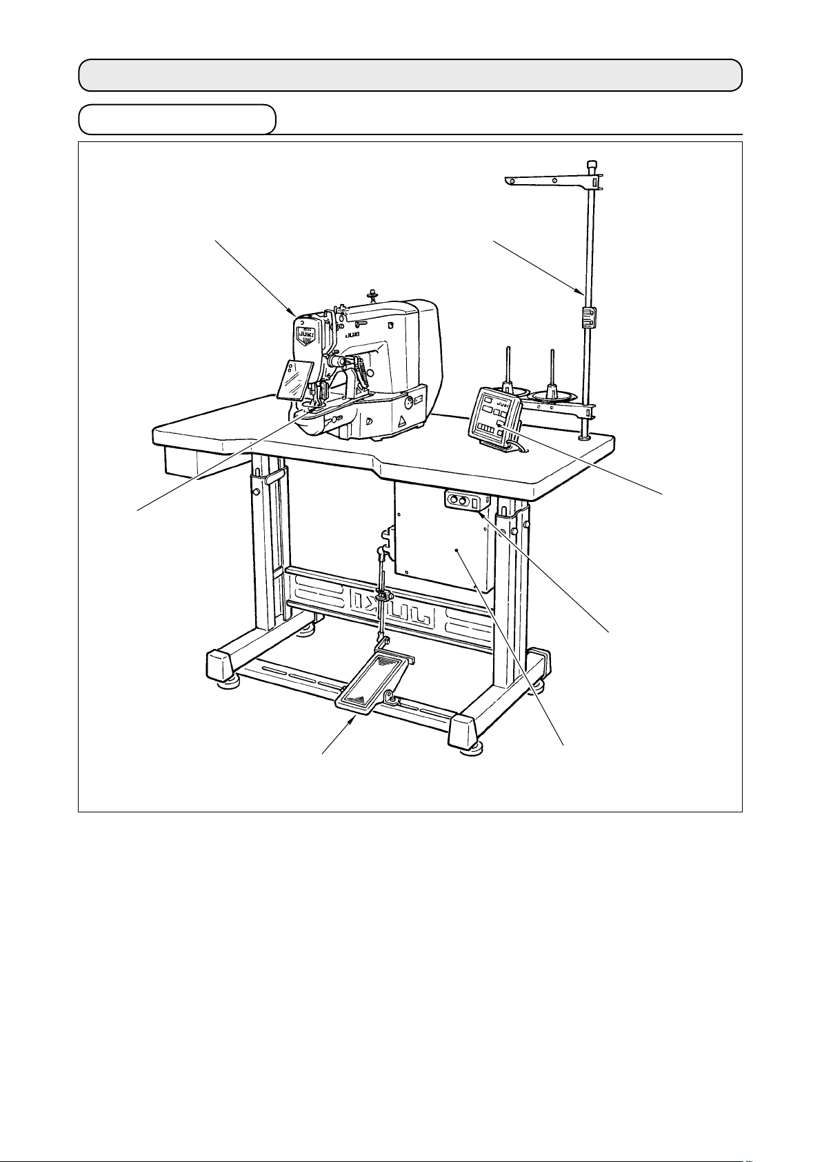
[2] CONFIGURATION .....................................................................................................................................2
1. Names of main unit................................................................................................................................................2
2. Names and explanation of switches on the operation panel ............................................................................3
[3] INSTALLATION .........................................................................................................................................4
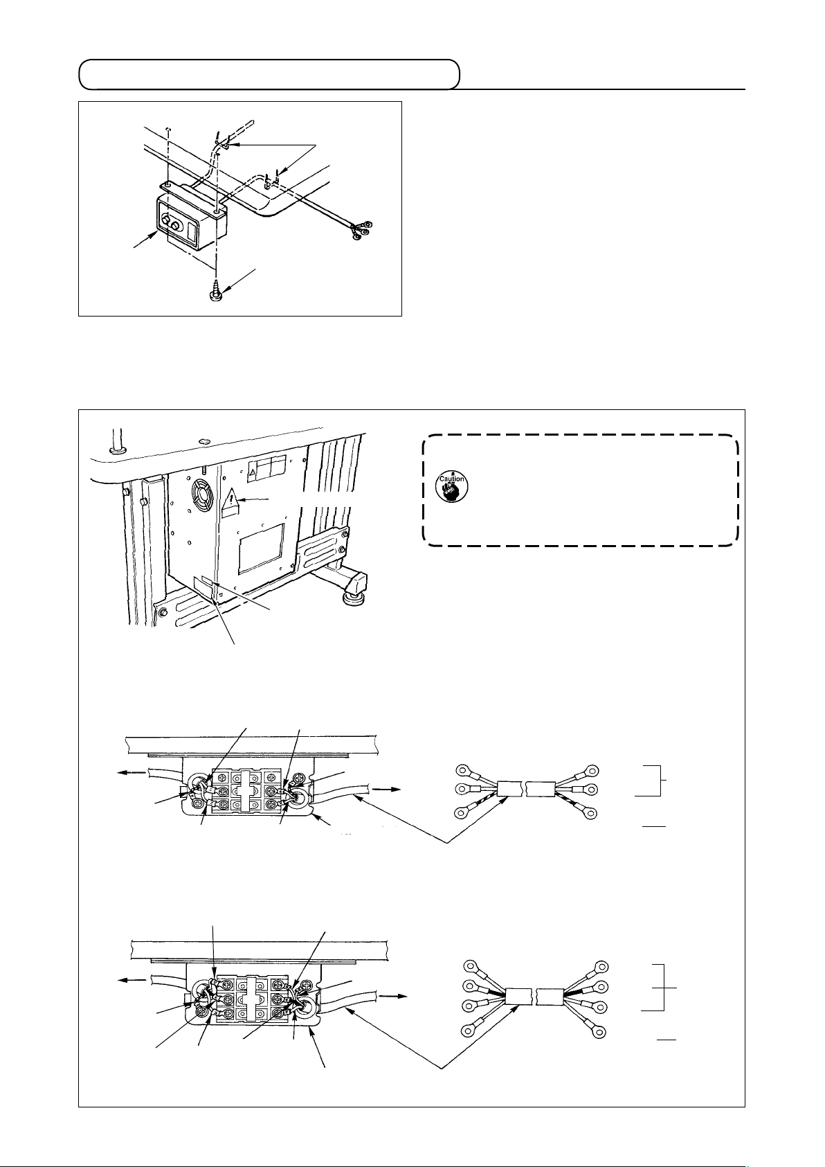
1. Installing the electrical box...................................................................................................................................4
2. Attaching the connecting rod...............................................................................................................................4
3. Installing the head support rod ............................................................................................................................4
4. Installing and connecting the power switch .......................................................................................................5
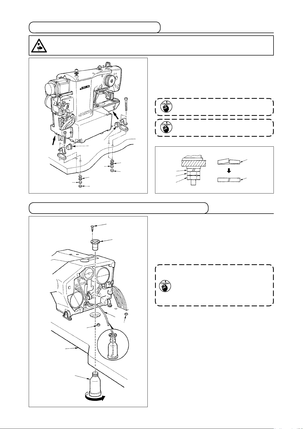
5. Installation of the sewing machine head.............................................................................................................6
6. Installing the drain receiver and the head support rubber ................................................................................6
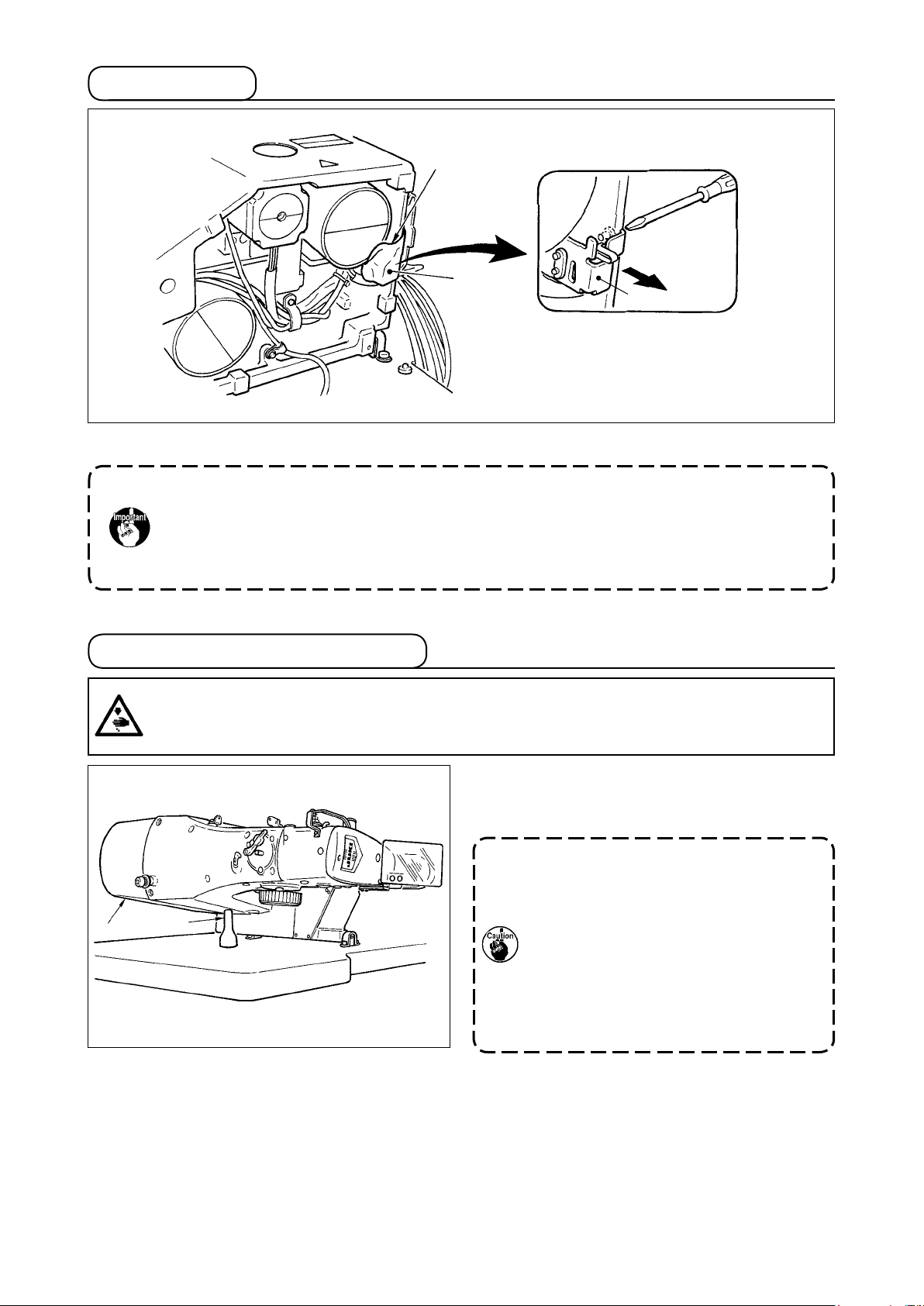
7. Safety switch..........................................................................................................................................................7
8. Tilting the sewing machine head .........................................................................................................................7
9. Installing the operation panel...............................................................................................................................8
10. Connecting the cord..............................................................................................................................................9
11. Installing the motor cover...................................................................................................................................10
12. Managing the cord............................................................................................................................................... 11
13. Installing the eye protection cover .................................................................................................................... 11
14. Installing the thread stand..................................................................................................................................12
[4] OPERATION OF THE SEWING MACHINE ............................................................................................13
1. Lubrication ...........................................................................................................................................................13
2. Attaching the needle ...........................................................................................................................................13
3. Threading the machine head ..............................................................................................................................14
4. Installing and removing the bobbin case ..........................................................................................................14
5. Installing the bobbin............................................................................................................................................15
6. Adjusting the thread tension ..............................................................................................................................15
7. Adjusting the thread take-up spring ..................................................................................................................16
8. Example of the thread tension ...........................................................................................................................16
[5] OPERATION OF THE SEWING MACHINE (BASIC)..............................................................................17
1. Item data setting ..................................................................................................................................................17
2. Checking the contour of a sewing pattern ........................................................................................................19
3. Sewing ..................................................................................................................................................................20
4. Change to the other sewing pattern ..................................................................................................................20
5. Winding a bobbin.................................................................................................................................................21
6. Thread clamp device ...........................................................................................................................................22
[6] OPERATION OF THE SEWING MACHINE (ADVANCED).....................................................................24
1. Performing sewing using the pattern keys ( , , , and ) ........................................24
2. Performing sewing using the combination function........................................................................................27
3. Performing sewing using the “bobbin thread counter”...................................................................................29
4. How to use the temporary stop ..........................................................................................................................29
5. Setting the pattern thread tension .....................................................................................................................30
6. Cautions in operation..........................................................................................................................................31
[7] MAINTENANCE ......................................................................................................................................31
1. Adjusting the height of the needle bar ..............................................................................................................31
2. Adjusting the needle-to-shuttle relation............................................................................................................32
3. Adjusting the lift of the work clamp foot ...........................................................................................................33
4. The moving knife and counter knife ..................................................................................................................33
5. Needle thread clamp device ...............................................................................................................................34
6. Adjustment of the wiper......................................................................................................................................34
7. Draining waste oil ................................................................................................................................................35
8. Amount of oil supplied to the hook ...................................................................................................................35
9. Replacing the fuse...............................................................................................................................................35

ii
10. Changing the voltage of 100/200V .....................................................................................................................36
11. Replenishing the designated places with grease.............................................................................................37
[8] HOW TO USE THE MEMORY SWITCH..................................................................................................38
1. Start and change of the memory switch............................................................................................................38
2. Example of the memory switch setting .............................................................................................................38
3. Table of functions of the memory switch ..........................................................................................................42
[9] OTHERS ..................................................................................................................................................45
1. Setting the DIP switch .........................................................................................................................................45
2.Tableofthestandardpatternspecications ....................................................................................................46
3. Table of the standard patterns ...........................................................................................................................47
4. Table of the work clamp foot ..............................................................................................................................49
5. LK-1900 data ROM ...............................................................................................................................................51
6. Connection of the optional pedal.......................................................................................................................51
7. Error list................................................................................................................................................................52
8. Troubles and corrective measures (sewing conditions)..................................................................................55
9. Table of the optional parts ..................................................................................................................................57
@. EXPLANATION OF THE LK-1901AN, COMPUTER-CONTROLLED HIGH-SPEED
EYELET BUTTONHOLE BARTACKING MACHINE...................................................59
1.Specications ......................................................................................................................................................59
2. Installation of the sewing machine and preparation of the operation............................................................59
3. Adjustment of the material closing amount......................................................................................................60
4. Adjustment of the lift of the work clamp foot ...................................................................................................60
5. Adjustment of the pressure of the work clamp unit.........................................................................................61
6. Setting of the material closing operation ..........................................................................................................61
7.Selectionandconrmationofthesewingpatterns .........................................................................................62
#. EXPLANATION OF THE LK-1902AN, COMPUTER-CONTROLLED HIGH-SPEED
BELT-LOOP ATTACHING MACHINE..........................................................................63
1.Specications ......................................................................................................................................................63
2.
Installation of the sewing machine and preparation of the operation ..................................................................... 63
3. Threading the machine .......................................................................................................................................63
4.Selectionandconrmationofthesewingpatterns .........................................................................................64
5. Combination of the work clamp foot and the feed plate..................................................................................64
$. EXPLANATION OF THE LK-1903AN, COMPUTER-CONTROLLED HIGH-SPEED
LOCKSTITCH BUTTON SEWING MACHINE.............................................................65
1.Specications ......................................................................................................................................................65
2. Installation of the sewing machine and preparation of the operation............................................................65
3. Needle and thread................................................................................................................................................65
4. Various sewing modes........................................................................................................................................66
5. Position of the button clamp jaw lever ..............................................................................................................67
6. Adjusting the feed plate ......................................................................................................................................68
7. Adjusting the button clamp jaw lever ................................................................................................................68
8. Adjusting the lifting amount of the button clamp.............................................................................................69
9. Adjustment of the pressure of the work clamp unit.........................................................................................69
10. Adjustment of the wiper spring..........................................................................................................................70
11. Installing the save button bar (accessory part)................................................................................................70
12.Modelclassicationaccordingtothebuttonsize............................................................................................71
13. Attaching the shank botton (optional)...............................................................................................................72
%. DRAWING OF THE TABLE..........................................................................................76

-1 -
!. EXPLANATION OF LK-1900AN, COMPUTER-CONTROLLED HIGH-
SPEED BARTACKING MACHINE
[1] SPECIFICATIONS
1 Sewing area X (lateral) direction 40 mm Y (longitudinal) direction 30 mm
2 Max. sewing speed 3,200 sti/min*(When sewing pitches are less than 5 mm in X-direction
and 3.5 mm in Y -direction.)
3 Stitch length 0.1 to 10.0 mm (adjustable in 0.1 mm step)
4 Feed motion of work clamp foot Intermittent feed (2-shaft drive by stepping motor)
5 Needle bar stroke 41.2 mm
6 Needle DP x 5, DPx17
7 Lift of work clamp foot 13 mm (standard) Max. 17 mm
8 Shuttle Standard semi-rotary hook (oil wick lubrication)
9 Lubricating oil New Defrix Oil No. 2 (supplied by oiler)
10 Data recording EEPROM (128Kbyte) EPROM (32kbyte)
11 Enlarging / Reducing facility 20% to 200% (1% step) in X direction and Y direction respectively
12 Enlarging / Reducing method Pattern enlargement / reduction can be done by increasing/decreasing
the stitch length
13 Max. sewing speed limitation 400 to 3,200 sti/min*(100 sti/min steps)
14 Pattern selection Specifying pattern No. type (1 to 200)
15 Bobbin thread counter UP/DOWN type (0 to 9999)
16 Sewing machine motor Servo motor
17 Dimensions W : 1,200 mm L : 660 mm H : 1,100 mm
(Use the standard table and stand.)
18 Weight Machine head 42 kg, Control box 16.5 kg
19 Power consumption 450 VA (Pattern No. 1, 3,200 sti/min, 1-sec pause time)
20 Operating temperature range 5 ˚C to 35 ˚C
21 Operating humidity range 35% to 85% (No dew condensation)
22 Line voltage Rated voltage ± 10% 50/60 HZ
23 Noise - Equivalent continuous emission sound pressure level (LpA) at the
workstation :
A-weighted value of 82.5 dB; (Includes KpA = 2.5 dB); according to
ISO 10821- C.6.3 -ISO 11204 GR2 at 3,200 sti/min for the sewing
cycle, 1.0s ON (Pattern : No.1).
- Sound power level (LWA) ;
A-weighted value of 90.5 dB; (Includes KWA = 2.5 dB); according to
ISO 10821- C.6.3 -ISO 11204 GR2 at 3,200 sti/min for the sewing
cycle, 1.0s ON (Pattern : No.1).
* Reduce the max. sewing speed in accordance with the sewing conditions.
Max. sewing speed of LK-1900ANWS (double capacity hook) is 2,700 sti/min.

-2 -
[2] CONFIGURATION
1. Names of main unit
1Machine head
2Work clamp feet
3Thread stand
4Operation panel
5Power switch
6Control box
7Pedal switch
1
2
3
4
5
6
7

-3 -
2. Names and explanation of switches on the operation panel
1“Ready” key
This key changes over the setting state from the
panel to the sewing state where the sewing ma-
chine actually operates.
2Sewing LED
This LED goes off at the time of setting state and
lights up at the time of sewing state. Changeover
can be performed with “Ready” key.
3“Reset” key
This key is used for canceling error or returning
the set value to the initial value.
4“Mode” key
This key makes the setting mode of the memory
switch.
5
“+/Feed forward” key and “-/Feed backward” key
This key is used for changing pattern No. and
X/Y scale, and feed forward/feed backward.
6“Selection” key
This key selects the item to be set. Item selec-
tion LED of the selected item and the set value
are displayed.
7Data indication LED
This LED indicates the set values of the select-
ed items such as pattern No., X/Y scale, etc.
8Item selection LED
LEDs of the selected items light up.
9Needle thread clamp ON/OFF key
This key selects effective/ineffective of needle
thread clamp. When it is effective, needle thread
clamp display LED lights up. (Note 1)
!0 Needle thread clamp display LED
When this LED lights up, needle thread clamp
operates.
!1 Needle thread clamp display LED
This key registers the pattern. When this key is
pressed, the pattern registered here can sew
immediately.
X/Y scale, sewing position, etc. can be changed
and registered.
Pattern No. X scale Y scale
Max. speed
limitation
Sewing
counter
Bobbin
winder
Work clamp
foot lowering
Thread
tension
1
2
5
43
6
7
8
9
!0!1
(Note 1) LK-1903AN is set to needle thread clamp prohibited (no motion) with memory switch No. 35
at the time of standard delivery.

-4 -
[3] INSTALLATION
1. Installing the electrical box
Install the electrical box on the underside of the table
at the location illustrated using round-head bolt 1,
plain washer 2, spring washer 3and nut 4sup-
plied with the machine, and using bolt having hex-
agonal indentation on the head 5, spring washer 6
and plain washer 7supplied with the machine.
1
2
3
A
B
2. Attaching the connecting rod
1) Fix connecting rod 1to installing hole Bof pedal
lever 2with nut 3.
2)
when connecting rod 1is installed in installing hole
A, the depressing stroke of the pedal is increased.
3. Installing the head support rod
Drive head support rod 1in hole 2in the machine
table.
1
2
1
2
3
4
5
6
7

-5 -
4. Installing and connecting the power switch
(1) Installing the power switch
Fix power switch 1under the machine table with
wood screws 2.
Fix the cable with staples 3supplied with the machine
as accessories in accordance with the forms of use.
* Five staples 3including the staple for fixing the
operation panel cable are supplied as accessories.
(2) Connecting the power source cord
Voltage specications at the time of delivery from the factry are indicated on the voltage indication seal.
Connect the cord in accordance with the specications.
1. Never use under the wrong volt-
age and phase.
2. When changing the voltage, refer
to the item of "!.[7]-10. Changing
the voltage of 100 / 200V" p.36.
Voltage indication seal (3-phase type only)
Voltage caution seal
Rating label
Table
Brown Brown
Brown
Light blue Light blue
Light
blue
Green/Yellow Green/
Yellow
Control box
Green/Yellow
Plug
Power source cord
Power switch GND
AC200 V
AC220 V
AC230 V
AC240 V
• Connecting single phase 200V, 220V, 230V and 240V
Table
Red
Black
Green/Yellow
White
Control box
Power source cord
Plug
Power switch
GND
AC200 V
AC220 V
AC240 V
• Connecting three phase 200V, 220V and 240V
Green/Yellow
Red
White
Black
G r e e n /
Yellow
Red
Black
White
1
2
3

-6 -
1) Fit hinge rubber 1 to the hinge shaft ,and x the
sewing machine main unit.
2) When tightening nut 3to hinge rubber 1, tighten
nut 3until spring washer 2becomes as B in the
illustration, and x it with nut 4.
If tightening hinge rubber 1excessively,
it will not work properly. So, be careful.
Hold section Awhen moving the sew-
ing machine.
5. Installation of the sewing machine head
A
A1
1
WARNING :
To prevent possible accidents caused by the full of the sewing machine, perform the work by two
persons or more when the machine is moved.
1) Fix drain receiver 2in the installing hole of table
1with four setscrews 3.
2) Screw in drain bin 4to drain receiver 2.
3) Insert sewing machine drain pipe 5into drain bin
4.
4) Insert head support rubber 6into table 1.
1. Insert drain pipe
5
until it will go no
further so that it does not come off
drain bin
4
when tilting the machine
head.
2. Removethetapexingdrainpipe
5
.
1
2
5
4
3
6. Installing the drain receiver and the head support rubber
2
3
4
2
34
2
3
4
2
2
6
6
A
B

-7 -
When tilting the sewing machine head, tilt the head
gently until it comes in contact with head support rod
1.
1. Before tilting the sewing machine
head, make sure that head support rod
1is attached to the machine table.
2. When raising the sewing machine
head, do not raise it while holding
motor cover 2. It will be the cause of
breakage of motor cover 2.
3.
Be sure to tilt the sewing machine head
onaatplacetopreventitfromfalling.
8. Tilting the sewing machine head
1
2
WARNING :
Tilt/raisethesewingmachineheadwithbothhandstakingcarenottoallowyourngerstobecaught
in the head. Turn OFF the power before starting the work so as to prevent accidents caused by abrupt
start of the sewing machine.
7. Safety switch
1
2
2
Remove tape 1 xing the lever section of safety switch 2.
1. When using the safety switch without removing tape 1,it is very dangerous since the
sewing machine works even in the state that it is tillted.
2. In case error 302 occurs when the sewing machine works after setup, loosen the safe-
tyswitchttingscrewwithascrewdriver,andlowertheswitchtothedownsideofthe
sewing machine.

-8 -
9. Installing the operation panel
Fix operation panel installing plate 1on the ma-
chine table with wood screws 2and pass the cable
through hole 4in the machine table.
Fix the operation panel on panel installing plate 1
with screws 3supplied as accessories.
Fix the cable on the bottom surface of the table with
the staples supplied with the machine as accessories.
Refer to the gure on the left side when installing the
panel under the table.
1
2
4
3
1
3
2

-9 -
CN38 Gray
10. Connecting the cord
Remove four screws E fixing the rear cover of the
electrical box. When opening the rear cover, press-
ing it with your hands, slowly open it by approximate-
ly 90˚ until it stops as illustrated.
Be sure to lend your hand to the rear
cover in order not to let the rear cover
fall. In addition, do not apply force to the
rear cover opened.
1
CN16
CN14
CN39
CN42
CN43
CN44
CN45
CN40
CN47
CN38
CN34
4P
9P
2P
6P
6P
6P
6P
4P
2P
16P
26P
White
Yellow
White
Blue
Red
Yellow
White
White
Gray
Gray
(LK-1901AN)
Sewing machine head
Operation panel
CN14 White
CN16 White
Earth cord
CN34 Gray
CN45
Yellow
CN47
White
CN42 White
CN43 Blue
CN39 Yellow
CN44 Red
CN40
White
Slowly
White

-10 -
1) Take care so that the cord is not caught between
the rear cover and the electrical box main body,
close the rear cover while pressing section A on
the lower side of the rear cover, and tighten four
screws 1.
2) Lower downward the cord located on the side of
the control box and cord presser plate C in the
push hole B, press the cord and tighten screws 2.
3
1Lightly press the corner of clamp.
(Cord clamp is locked with a click.)
How to lock the cord clamp
1
2
1
1
2
A
B
C
11. Installing the motor cover
Install motor cover 1on the machine main unit with
screws supplied with the machine as accessories.
1
1
1
2
Clamp
How to remove the cord clamp
1Lightly pressing
2
Pull down the clamp.
3
The clamp goes up.

-11 -
12. Managing the cord
1
2
Slack
Be sure to use eye protection cover 1after install-
ing it on installing section 3with screws 2.
13. Installing the eye protection cover
1
1) In the state that the sewing machine is tilted, connect the cords, and bundle them with clip band 1
as shown in the gure.
2) Fix the cords with cords setting plate 2 in the state that the cords slacken as shown in the gure.
When you tilt the sewing machine, make sure that the sewing machine head support bar is
placed on the table.
WARNING :
Be sure to attach this cover to protect the eyes from the disperse of needle breakage.
3
2

-12 -
14. Installing the thread stand
1) Assemble the thread stand unit, and insert it in
the hole in the machine table.
2) Tighten locknut 1 to x the thread stand.
3) For ceiling wiring, pass the power cord through
spool rest rod 2.
1
2

-13 -
Loosen setscrew 1and hold needle 2with the long
groove 3facing toward you. Then fully insert it into
the hole in the needle bar, and tighten setscrew 1.
If the stitches are made as shown in A,
attach the needle facing to the direction
Ato a small extent.
[4] OPERATION OF THE SEWING MACHINE
1. Lubrication
2. Attaching the needle
2
3
A
B
WARNING :
Turn OFF the power before starting the work so as to prevent accidents caused by abrupt start of the
sewing machine.
WARNING :
Turn OFF the power before starting the work so as to prevent accidents caused by abrupt start of the
sewing machine.
1
Check that the place between lower line B and upper
line A is lled with oil. Fill there with oil using the oiler
supplied with the machine as accessories when oil is
short.
* The oil tank which is lled with oil is only for lubri-
cating to the hook portion. It is possible to reduce
the oil amount when the number of rotation used
is low and the oil amount in the hook portion is
excessive. (Refer to "!.[7]-8. Amount of oil
supplied to the hook" p.35.)
1. Do not lubricate to the places other
than the oil tank and the hook of Cau-
tion 2 below. Trouble of components
will be caused.
2. When using the sewing machine for
thersttimeorafteranextendedpe-
riod of disuse, use the machine after
lubricating a small amount of oil to
the hook portion. (Refer to "!.[7]-2.
Adjusting the needle-to-shuttle rela-
tion" p.32.)
A
B

-14 -
1) Open hook cover 1.
2) Raise latch 3of bobbin case 2, and remove the
bobbin case.
3) When installing the bobbin case, fully insert it into
the shuttle shaft, and close the latch.
If it is not fully inserted, bobbin case 2
may slip off during sewing.
3. Threading the machine head
Pull out the thread by approximately 40mm from the needle after threading through the needle.
1. When the silicon oil is used, thread through thread guide for silicon 1(Optional)
2. For thick thread, pass the thread through one hole only of needle bar thread guide 2.
4. Installing and removing the bobbin case
1
2
3
WARNING :
Turn OFF the power before starting the work so as to prevent accidents caused by abrupt start of the
sewing machine.
WARNING :
Turn OFF the power before starting the work so as to prevent accidents caused by abrupt start of the
sewing machine.
1
2
Thin synthetic thread or the like

-15 -
Adjusting the needle thread tension
1) Select thread tension with key.
2)
Set needle thread tension with key or
key. There is a setting range of 0 to 200. When the
set value is increased, the tension becomes higher.
* The tension is set so that 1.5 N (spun thread
#50) is obtained at the set value 50 at the time
of standard delivery. (When thread tension No.
1 is released)
6. Adjusting the thread tension
If thread tension controller No. 1 1is turned clock-
wise, the length of remaining thread on the needle
after thread trimming will be shorter. If it is turned
counterclockwise, the length will be longer.
Shorten the length to an extent that the thread is not
slipped off.
Adjust needle thread tension from the operation pan-
el and bobbin thread tension with 2.
1
Short
Long
h
1) Set the bobbin 1into bobbin case 2in the di-
rection shown in the gure.
2) Pass the thread through thread slit 3of bobbin
case 2, and pull the thread as it is. By so doing,
the thread will pass under the tension spring and
be pulled out from thread hole 4.
3) Pass the thread through thread hole 5of the
horn section, and pull out the thread by 25mm
from the thread hole.
If the bobbin is installed in the bobbin
case orienting the reverse direction, the
bobbin thread pulling out will result in
an inconsistent state.
5. Installing the bobbin
12
5
4
3
25mm
WARNING :
Turn OFF the power before starting the work so as to prevent accidents caused by abrupt start of the
sewing machine.
2

-16 -
7. Adjusting the thread take-up spring
The standard stroke of thread take-up spring 1is 8
to 10 mm, and the pressure at the start is 0.1 to 0.3N.
1) Adjusting the stroke
Loosen setscrew 2, and turn thread tension asm.
3.
Turning it clockwise will increase the moving
amount and the thread drawing amount will in-
crease.
2) Adjusting the pressure
To change the pressure of the thread take-up
spring, insert a thin screwdriver into the slot of
thread tension post 4while screw 2is tightened,
and turn it. Turning it clockwise will increase the
pressure of the thread take-up spring. Turning it
counterclockwise will decrease the pressure.
1
4
32
8. Example of the thread tension
When using the sewing machine for the rst time, adjust the thread tension referring to the table below.
Thread
Polyester lament thread #50
Polyester spun thread #50
Polyester spun thread #60
(Thread clamp OFF)
Cotton thread #50
Cotton thread #20
Material
Wool
Wool
T/C broad
Denim
Denim
Needle thread tension
setting
30 to 35
50 to 55
30 to 35
35 to 45
35 to 45
Thread take-up spring moving
amount [Thread drawing amount]
10mm [13mm]
10mm [13mm]
8 to 10mm [11 to 13mm]
10mm [13mm]
8 to 10mm [11 to 13mm]
Strength
0.1N
0.2N
0.1N
0.1N
0.1N

-17 -
(3) Setting of the X scale
1) Press the key to indicate the item “X Scale”
.
2) Press the or key to indicate “100”.
(Set X scale to 100%.)
The setting exceeding 100% is danger-
ous since needle and the cloth presser
interferes with each other and needle
breakage or the like will occur.
[5] OPERATION OF THE SEWING MACHINE (BASIC)
1. Item data setting
Set each item following the procedure described below.
(1) Turn ON the power switch.
Pattern No. of the item selection lights up, and the pattern No. is indicated on the data display.
(2) Setting of the pattern No.
1) Press the key to indicate the item “Pattern
NO” .
2) Press the or key to indicate “ 14 ”on
the display. (Pattern No. is set to 14.)
Refer the pattern No. to the separate table.
Setting of the
pattern No.
Setting of the
X scale
Setting of the
Y scale
Setting of the
max. sewing
speed limitation
Setting the
thread tension
eee e
(4) Setting of the Y scale
1) Press the key to indicate the item “Y Scale”
.
2) Press the or key to indicate “100”.
(Set Y scale to 100%.)
The setting exceeding 100% is danger-
ous since needle and the cloth presser
interferes with each other and needle
breakage or the like will occur.
h
h
h
This manual suits for next models
3
Table of contents
Other JUKI Sewing Machine manuals

JUKI
JUKI MO-634DE User manual

JUKI
JUKI MO-6000G Series Quick start guide

JUKI
JUKI IP-100 Quick start guide

JUKI
JUKI LBH-772NV-1 User manual

JUKI
JUKI AK118 User manual

JUKI
JUKI MO-102 User manual

JUKI
JUKI HZL-35Z User manual

JUKI
JUKI MO-6900R Series User manual

JUKI
JUKI MH-481 User manual

JUKI
JUKI PS-700 User manual

JUKI
JUKI HZL-30Z User manual

JUKI
JUKI PLC-1690 User manual

JUKI
JUKI LH-4128-7 Quick start guide

JUKI
JUKI SC-920 User manual

JUKI
JUKI LZ-2290A-SR/IP-110D/SC-916 User manual

JUKI
JUKI MF-3620 User manual

JUKI
JUKI MB-373 Series User manual

JUKI
JUKI LH-512 User manual

JUKI
JUKI LK-1903A-305 User manual

JUKI
JUKI DDL-9000 User manual