–7 –
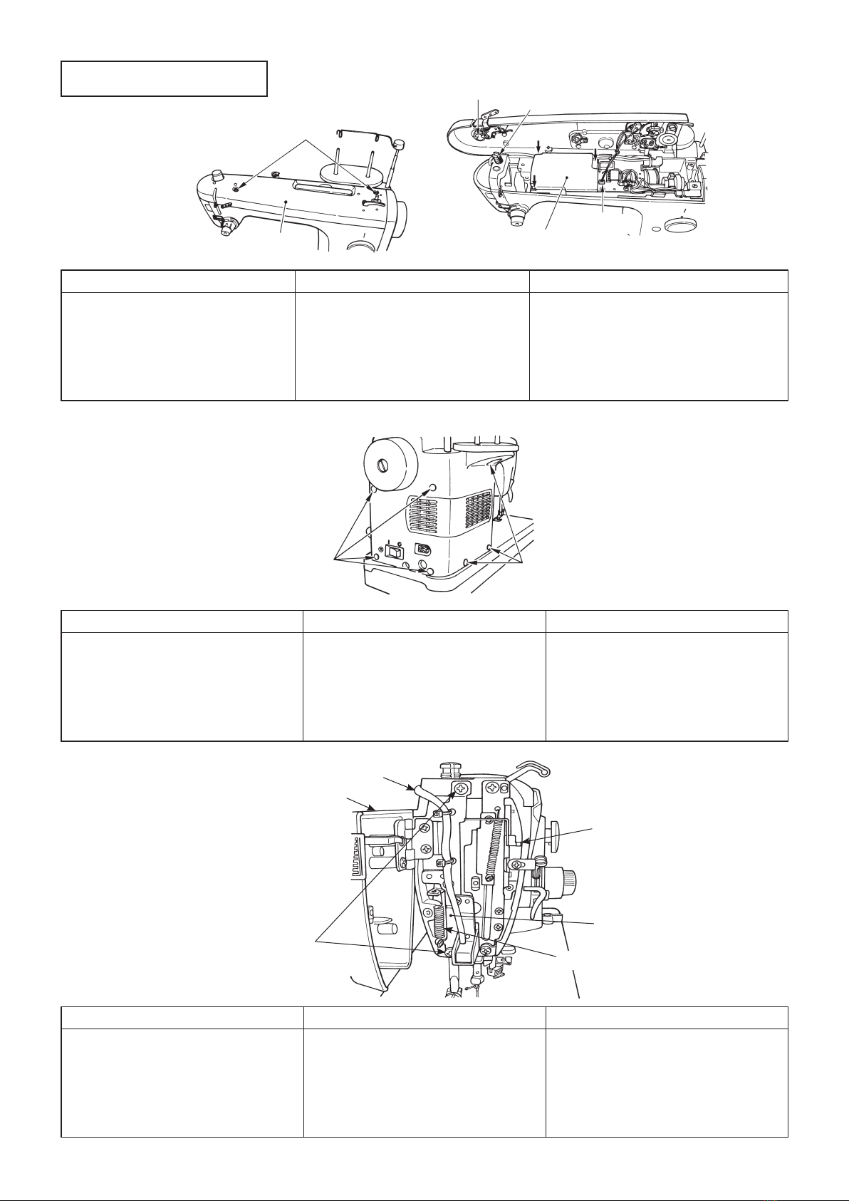
4. Presser bar
Preparation
○Remove arm cover asm.
○Remove face plate mas. asm.
○Remove presser foot and setscrew.
❻ Presser bar lifting lever
❽ Hand lifter lever
❸ Presser bar
❷ Presser spring regulator
❼ Indicating needle of
presser spring regulator
❹ Presser spring
❺ Presser bar connection asm.
❶ Presser bar connection setscrew
SM8060502TP
Threader support plate
setscrew (upper)
SL5040631SE
Threader support plate mas. asm.
Threader support plate
setscrew (lower)
SM4040655SN
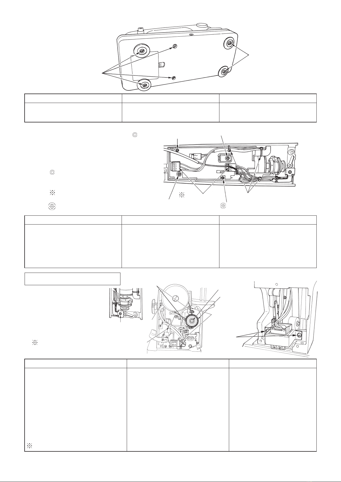
5. Needle bar
Preparation
○Remove arm cover asm.
○Remove face plate mas. asm.
○Remove presser bar.
○Remove needle bar threading guide
as well.
Needle bar
crank left screw
❶ Needle bar upper bushing felt
❷ Needle bar connection setscrew
SM8060510SP
❻ Needle bar threader guide setscrew
❺ Needle bar
❹ Needle clamp
❸ Needle bar thread bracket setscrew
A1420-001-000
Disassembly Assembly Point
○ Lower ❽lever and loosen ❶set-
screw.
○ Drawing ❸upward, remove ❹
spring.
○ Remove ❺connection and ❻lever.
○ Remove regulator ❷screw.
○ Do not remove ❼indicating needle.
❸is hard to remove since secrew
mark is attached.
○Attach regulator ❷screw.
○Set ❻lever to frame, and
then set ❺connection.
○Attach
❹spring when setting
❸presser bar from upper
side.
○Set
❹spring under ❼indicating
needle.
○Lower ❽lever and temporarily
tighten it at the position where top
end of ❸protrudes approximately
4 mm from frame.
For the adjustment, see item 3 on
page 18.
○Needle should not interfere with
presser foot.
Disassembly Assembly Point
○Remove
❸and ❹.
○Remove ❶felt. (Push up
needle bar upper bushing ❶
felt with ❺and draw it out.)
○Loosen setscrew of ❷and
❻. (Pushing needle bar ❺
upward is acceptable.)
○Draw out ❺upward.
○Remove left ❻screw and re-
move crank rod.
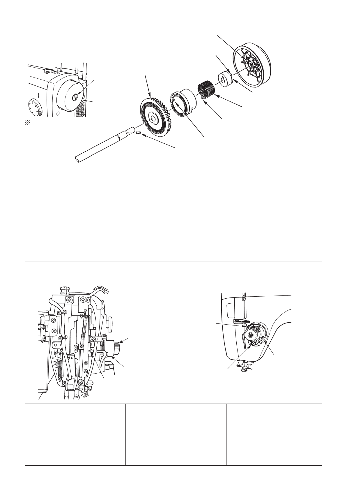
○Attach crank rod and tighten it with
❻.
○Perform positioning of needle bar
and tighten needle bar connection
❷setscrew.
○Set needle bar and attach ❹and ❸.
○Insert
❶into hole.
○Temporarily tighten ❻, and perform
adjustment of vertical height after at-
taching threader support plate asm.
○Position of needle bar is the place
where upper engraved line of
needle bar is aligned with lower
end face of needle bar bushing at
the needle lower dead point.
See item 2 on page 18 for the ad-
justment.
○See item 15 on page 23 for height
adjustment of threader hook of
threader support plate mas. asm.