– 3 –
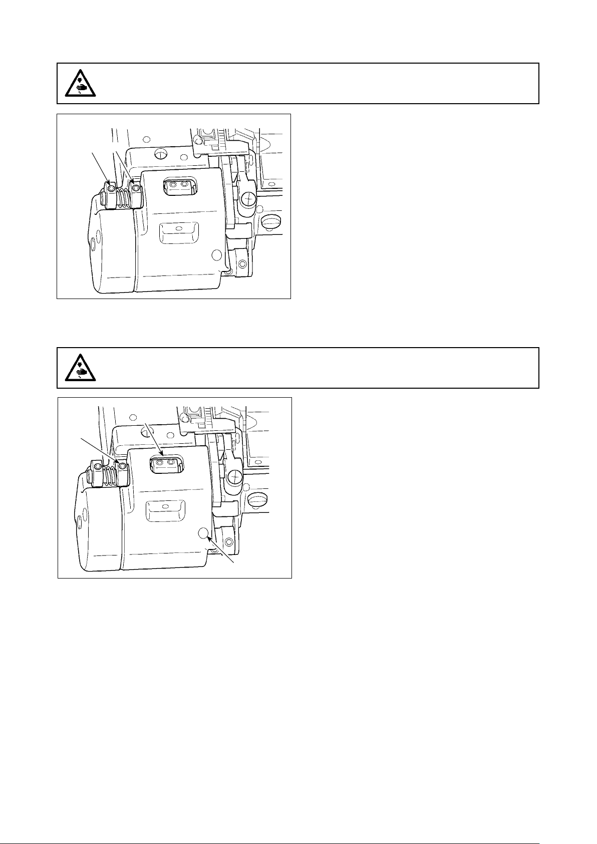
1)
Loosen setscrew ❶ of the adjusting lever. Adjust the
sharpness of the knife by turning the adjusting lever
counterclockwise according to the sharpness of the
knife.
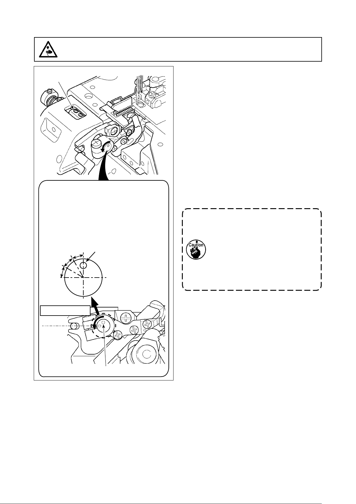
2)
After the adjustment of the knife sharpness, tighten set-
screw ❶ of the adjusting lever.
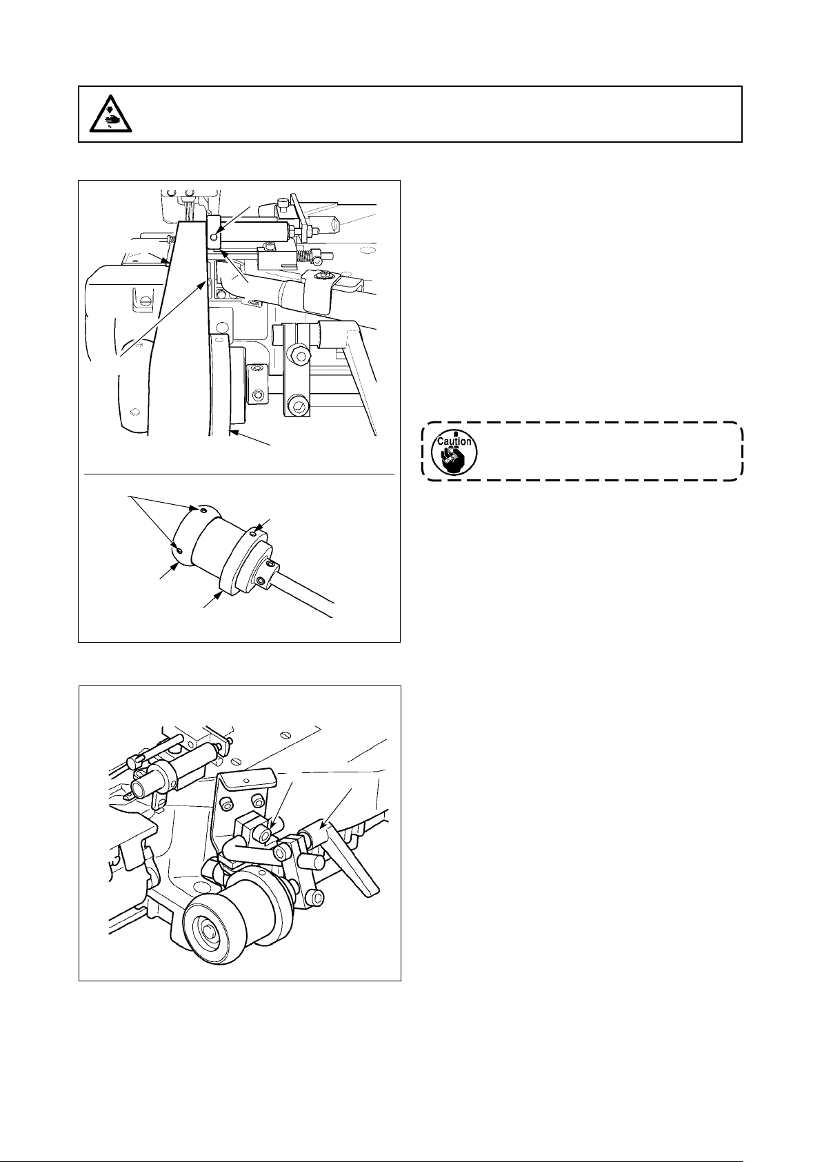
3)
After the adjustment of the engagement, carry out "3.
ADJUSTING THE UPPER KNIFE PRESSURE" p.2
and "2. ADJUSTMENT PROCEDURE OF ENGAGE-
MENT AMOUNT OF KNIVES" p.1.
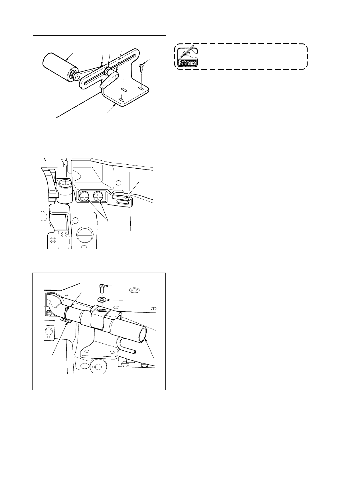
4)
In the delivered state of the sewing machine, the posi-
tion of marker dot A orients to the 12 o'clock direction,
as observed from the pulley side, when the knife is in
its lower dead point. Adjust to decrease the angle of
mesh bit by bit such as from 12 o'clock to 11 o'clock,
then to 10 o'clock.
1. The extent of the adjustment of the angle of
mesh is until marker dot A is turned coun-
terclockwise to reach the horizontal posi-
tion. If the lever is turned beyond the above,
the angle between the upper knife and the
lower knife will increase.
2. If the depth of engagement is excessively
increased, the knife can wear.
3. Adjust the knife so that it cuts well and the
depth of engagement is not excessive
Counterclockwise turn
❶
Marker dot A
B: Standard adjustment angle
C:
Angle adjusted for hard-to-sew materials
D:
Angle adjusted when the knife has worn
* If the knife engagement angle is adjusted to
D from the start, the knife can wear earlier
than the case where the angle is adjusted
the standard one.
Horizontal
position
B
C
D
Marker dot A
5. ADJUSTING THE ENGAGEMENT ANGLE OF THE KNIFE
WARNING :
To protect against possible personal injury due to abrupt start of the machine, be sure to start the follow-
ing work after turning the power off and ascertaining that the motor is at rest.