CONTENTS
1. SPECIFICATIONS...........................................1
2. NAME OF EACH COMPONENT ....................2
3. INSTALLATION ..............................................3
3-1. Table ...................................................................3
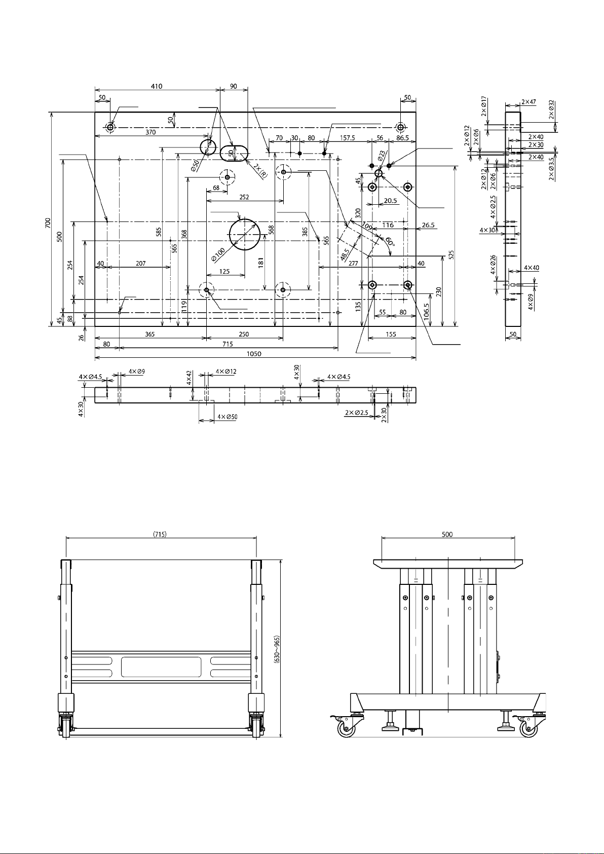
(1) Drawing of the table............................................... 4
(2) Drawing of the stand.............................................. 4
3-2. Installing the control box.................................. 5
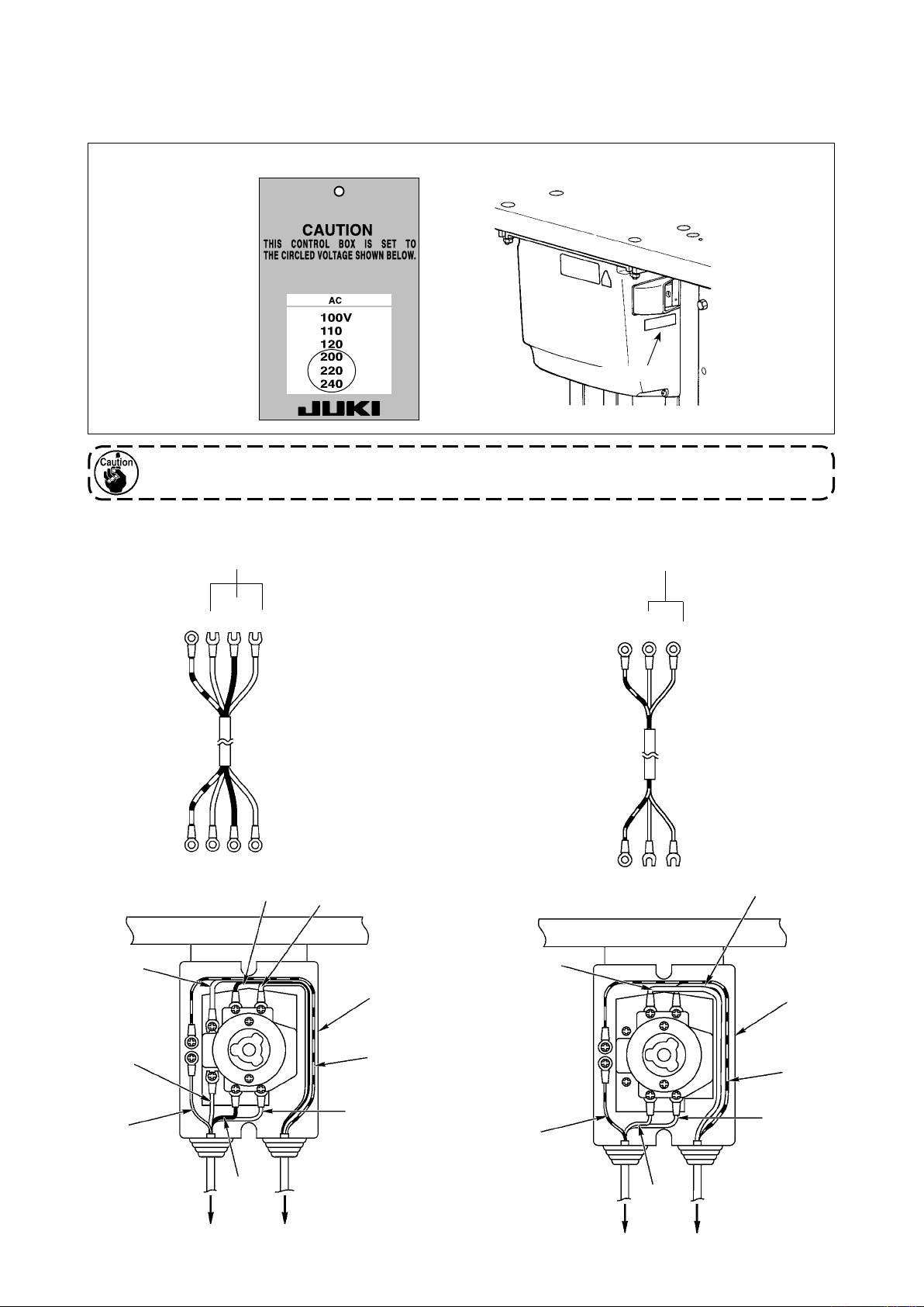
3-3. Installing and connecting the power
switch .................................................................5
3-4. Taking out the sewing machine .......................7
3-5. Installing the sewing machine.......................... 8
3-6. Raising and returning the sewing machine .. 10
3-7. Installing the poly oiler ...................................13
3-8. Installing the operation panel......................... 13
3-9. Installing the regulator and the manifold ......14
3-10. Connecting the cords...................................... 16
3-11. Handling the cords .......................................... 17
3-12. Installing the foot pedal switch (optional)..... 18
3-13. Connecting the air supply ..............................19
(1) Connecting the regulator and the manifold ..... 19
(2) Connecting the air tubes ................................... 20
3-14. Installing the air hose...................................... 21
3-15.
Cautions for the compressed air supply
(source of supply air) facility ........................... 22
3-16. Installing the thread stand.............................. 23
3-17. Installing the thread guides............................ 24
3-18. Installing the eye protection cover and the
nger guard ....................................................25
3-19. Installing the cloth chip bag ...........................26
3-20. Installing/removing the presser unit.............. 27
4. PREPARATION BEFORE OPERATION.......28
4-1. Lubrication of the machine and how to lu-
bricate...............................................................28
(1) Lubricating the arm oil tank .............................. 28
(2) Lubricating the bed oil tank............................... 28
(3) Lubricating the looper and spreader compo-
nents .................................................................... 29
(4) Lubricating the looper bracket oil tank ............ 29
(5) Lubricating the needle bar and the gear sec-
tion ....................................................................... 30
4-2. Attaching the needle .......................................31
4-3. Threading the machine head.......................... 32
(1) Threading the upper thread (needle thread) .... 32
(2) Threading the lower thread (looper thread) ..... 33
(3) Threading the machine with gimp .................... 34
4-4. How to set the cloth on the sewing ma-
chine .................................................................34
5. STRUCTURE OF THE OPERATION
SWITCH ........................................................35
5-1. Structure of the operation panel ....................35
5-2. Temporary stop switch ...................................37
5-3. Hand switch .....................................................37
5-4. Foot switch (optional) ..................................... 37
6. HOW TO USE THE OPERATION PANEL ....38
6-1. Basic operation of the sewing machine ........ 38
6-2. Setting the thread tension .............................. 38
6-3. Temporarily stopping the sewing machine...39
6-4. Performing re-sewing...................................... 40
6-5. Performing threading ...................................... 41
6-6. How to use the counter................................... 41
6-7. When dropping of the knife is temporarily
not desired ......................................................42
6-8. Changing the operation mode........................ 42
6-9. Changing procedure of the sewing pattern .. 44
6-10. Conrming the pattern shape ........................44
7. SETTING PROCEDURE OF THE SEWING
DATA .............................................................45
7-1. Setting the knife No......................................... 46
7-2. Setting the cut length...................................... 46
7-3. Setting the cut-before/cut-after knives.......... 47
7-4. Setting the number of stitches of the paral-
lel section ........................................................ 47
7-5. Setting the number of stitches of the eye-
let ......................................................................47
7-6. Setting the cut space ......................................48
7-7. Setting the eyelet space.................................. 48
7-8. Knife position compensation ......................... 48
7-9. Number of stitches of sewing end compen-
sation................................................................49
7-10. Turning angle compensation..........................49
7-11. Turning angle compensation at the parallel
section..............................................................49
7-12. Compensation of eyelet in lateral direction .. 50
7-13. Compensation of eyelet in longitudinal di-
rection ..............................................................50
7-14. Compensation of eyelet, left in longitudinal
direction ...........................................................50
7-15. Compensation of left parallel section of a
buttonhole........................................................51
7-16. Compensation of cutting space, left.............. 51
7-17.
Setting the needle throwing width of the
right bottom of eyelet .................................51
7-18.
Setting the needle throwing width of the
left bottom of eyelet ...................................52
7-19. Setting the needle throwing width ................52
7-20. Setting the type of bartack .............................52
7-21. Setting the length of taper bar ......................53
7-22. Setting the number of stitches of taper bar ..53
7-23. Setting the offset of taper bar ........................ 53
7-24. Setting the number of stitches of slant sec-
tion of taper bar ............................................... 54
7-25. Compensation of the number of stitches of
the right side taper bar ................................... 54
7-26. Setting the straight bar length ....................... 54
7-27. Setting the number of stitches of straight
bar.....................................................................55
7-28. Setting the overlapping amount of straight
bar.....................................................................55
7-29. Setting the needle throwing width of
straight bar.......................................................55
i