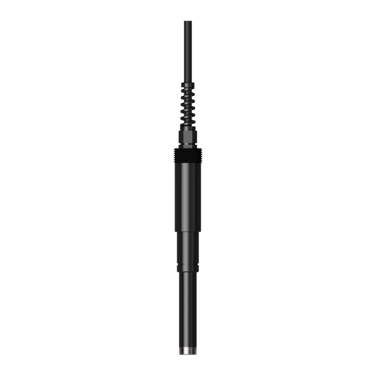
JUMO 902454/10 User manual

90245400T90Z001K000
V1.00/EN/00731587/2020-01-27
Temperature Probes
for Combined Cold/Heat Meters
Basic types 902454/10 and 902454/11
Basic type 902464/10
Operating Manual


Contents
Contents
1 Safety information. . . . . . . . . . . . . . . . . . . . . . . . . . . . . . . . . . . . . . . . . . . . 5
2 General information . . . . . . . . . . . . . . . . . . . . . . . . . . . . . . . . . . . . . . . . . . 7
2.1 Object of these instructions and purpose of application . . . . . . . . . . . . . . . . . . . . . . . . . . . .7
2.2 Identification marking . . . . . . . . . . . . . . . . . . . . . . . . . . . . . . . . . . . . . . . . . . . . . . . . . . . . . .7
3 Technical data . . . . . . . . . . . . . . . . . . . . . . . . . . . . . . . . . . . . . . . . . . . . . . . 9
4 Installation . . . . . . . . . . . . . . . . . . . . . . . . . . . . . . . . . . . . . . . . . . . . . . . . . . 11
4.1 Installation notes . . . . . . . . . . . . . . . . . . . . . . . . . . . . . . . . . . . . . . . . . . . . . . . . . . . . . . . . . .12
4.2 Temperature probes for direct mounting (902454/10 and 902454/11) . . . . . . . . . . . . . . . . .13
4.3 Temperature probes in thermowells (902464/10) . . . . . . . . . . . . . . . . . . . . . . . . . . . . . . . . .14
5 Maintenance. . . . . . . . . . . . . . . . . . . . . . . . . . . . . . . . . . . . . . . . . . . . . . . . . 17
6 Declaration of conformity. . . . . . . . . . . . . . . . . . . . . . . . . . . . . . . . . . . . . . 19
7 China RoHS . . . . . . . . . . . . . . . . . . . . . . . . . . . . . . . . . . . . . . . . . . . . . . . . . 21

Contents

5
1 Safety information
1 Safety informat ion
General
This manual contains information that must be observed in the interest of your own safety and to avoid
material damage. This information is supported by symbols which are used in this manual as indicated.
Please read this manual before starting up the device. Store this manual in a place that is accessible to
all users at all times.
If difficulties occur during startup, please do not intervene in any way that could jeopardize your warranty
rights!
Warning symbols
WARNING!
Risk of burns!
The installation process must be carried out by trained personnel.
When using water additives (corrosion protection, etc.), the operator must make sure there is sufficient
corrosion resistance before installing the temperature probe.
With direct mounting, the temperature probe is immersed in the pipeline without any additional immer-
sion sleeve. During dismounting, always make sure that hot medium does not escape from the pipeline.
Drain the pipeline system or seal off the temperature probe's installation location to relieve pressure.
The following standards and directives apply to the use of pairs of temperature probes for measuring the
forward flow and reverse flow temperature in a heat exchanger system:
• Product standard DIN EN 1434
• Product standard DIN EN 60751:2009 / IEC 60751:2008
• Directive 2014/32/EU, Annex I and MI-004
• German Weights and Measures Act (MessEG)
• German Weights and Measures Directive (MessEV)
Specifications for electrical installations must be observed.
All installation and maintenance work must be performed by specialist staff trained for this task.
All notes listed in the installation instructions must be observed.
Identification markings and metrology-relevant safety markings/main stamps must not be damaged or
removed – otherwise the temperature probes are no longer admissible for use!
Route the measurement signal lines so that they are at least 50 mm away from other lines, such as grid
supply lines and data transmission lines. We recommend installing lines and computer units 300 mm
away from strong electromagnetic fields, e.g. from frequency-controlled pumps and high-voltage power
lines.
To protect against damage and pollutants, the temperature probes must not be removed from their pack-
aging until immediately before installation.
Do not wind, bend, extend, or shorten the temperature probe lines.
When connecting to a computer unit, always connect the temperature probes first before connecting the
volume measuring unit.

1 Safety information
6

7
2 General information
2.1 Object of these instructions and purpose of application
The standard DIN EN 1434, as well as PTB Directive K7.2, describe the requirements for cold meters
and combined cold/heat meters und their sub-components. When combining sub-components (flow sen-
sor, pair of temperature probes, computer unit) to form a heat meter, the standard prescribes platinum
RTD temperature probes according to the standard DIN EN 60751:2009 / IEC 60751:2008 because
these probes have sufficient measurement stability, accuracy, and interchangeability.
These days, the latest cold meters use various nominal values on the computer unit side (resistance val-
ue at 0 °C). The nominal values are normally 100 Ω (Pt100), 500 Ω (Pt500), and 1000 Ω (Pt1000).
The RTD temperature probes in the type series 902454/10 and 902454/11 for direct mounting, and
902464/10 for installation in thermowells have national type approval for cold meters. When it comes to
use on combined cold/heat meters, these temperature probes also have an EC type examination in ac-
cordance with EC Directive 2014/32/EU (MID) including Appendices I and MI-004. The paired tempera-
ture probes are suitable for being connected to a computer unit of a combined cold/heat meter and
measure the difference between the forward flow and reverse flow temperature of a heat exchanger sys-
tem.
The temperature probes are made up of a corrosion-resistant protection fitting.
In order to meet the metrological requirements of PTB Directive K7.2 and EC Directive 2014/32/EU
(MID) and Annex MI-004, the temperature probes are calibrated at three temperatures and paired ac-
cording to a special mathematical process in order to comply with the tolerance for the temperature dif-
ference. The lower limit for the temperature difference is 3 K.
2.2 Identification marking
Each temperature probe pair is equipped with a nameplate containing the following information:
• CE identification marking with ID codes for the notified bodies appointed to certify module D (produc-
tion quality assurance)
• Metrology identification marking, including the two digits for the year in which the identification mark-
ing was created
• Logo for the owner of the type examination certificate
• Type examination certificate number
• Pair number/ID
• Manufacturing date (year/calendar week)
• Manufacturing location (in-house code)
• Type number
• Admissible measuring range (temperature, temperature difference)
• Maximum pressure stage
• Nominal value
• Manufacturer's address
The inflow and outflow probes are distinguished by colored identification markings on the temperature
probe's cable (red: inflow, blue: outflow) or using an identification marking on the nameplate (V = inflow,
R = outflow).
2 General information
8

9
3 Technical data
3 Technical d ata
Temperature range
902454/10 0 to 120 °C
902454/11 0 to 120 °C
902464/10 0 to 120 °C
The maximum operating temperature of the thermowells must be observed.
Protection type IP65 (as delivered condition)
Temperature difference
Minimum 3 K
Maximum 120 K
Maximum pressure
902454/10 PS25 for a water flow velocity of 2 m/s
902454/11 PS25 for a water flow velocity of 2 m/s
902464/10 With thermowells basic type 902440/47, 902440/48 and 902440/49
PS40 for a water flow velocity of 2 m/s
Electrical connection 2-wire circuit, 4-wire circuit
Maximum measuring current The maximum measuring current is calculated using the maximum admissible
power loss of 5 mW.
Depending on the nominal values, this results in the following effective current
values:
Pt100: 1783 µA
Pt500: 797 µA
Pt1000: 564 µA
Response times
902454/10 t
0.5
= 5 s; t
0.63
= 7 s; t
0.9
= 12 s;
902454/11 t
0.5
= 5 s; t
0.63
= 7 s; t
0.9
= 12 s;
902464/10 without thermowell t
0.5
= 5 s; t
0.63
= 7 s; t
0.9
= 12 s;
902464/10 with thermowell
902440/47
t
0.5
= 10 s; t
0.63
= 14 s; t
0.9
= 27 s;
902464/10 with thermowell
902440/48
t
0.5
= 11 s; t
0.63
= 15 s; t
0.9
= 28 s;
902464/10 with thermowell
902440/49
t
0.5
= 12 s; t
0.63
= 16 s; t
0.9
= 32 s;
Minimum immersion depth 30 mm
Nominal value Pt100, Pt500, Pt1000 (see identification marking for temperature probes)
Tolerance Class B according to DIN EN 60751:2009 / IEC 60751:2008; restricted toler-
ances optional
When using two-wire technology, the display will be systematically higher due
to the line resistance (see maximum connection length according to
DIN EN 1434).

3 Technical data
10

11
4 Installation
4
Installation
If the pair of temperature probes is connected to a computer unit, make sure that the probe's nominal
value matches that of the processing computer unit.
Furthermore, make sure that the installation location is deep enough to prevent damage to the tip of the
probe or thermowell when screwing in.
The temperature probe must be installed in the pipe so that a sufficient immersion depth is guaranteed
which is greater than the minimum immersion depth in all cases.
To prevent an inductive effect, the connecting cable must not be wound.
The connecting cable must not be laid alongside or wrapped around hot pipes because the line resis-
tance and its temperature dependence are considered in the measurement result for temperature probes
using two-wire technology.
Following successful mounting, the temperature probes must be secured against manipulation with a
seal. The seal holes in the fastening screw, the cold barrier at the terminal head, or special sealing eye-
lets are provided for this. The sealing set is available as part no. 00650727.
The maximum length for connecting cables in two-wire technology depends on the conductor cross sec-
tion and the nominal value according to DIN EN 1434-2. If the maximum admissible length, which may
be connected to the computer unit, has a lower value, this value applies (to be taken from the type ex-
amination certificate).
When choosing a connecting cable, make sure that the sheath material is sufficiently age resistant. The
connecting cable's outer diameter should be chosen so that there can be a secure seal for the cable en-
try to the terminal head (terminal head shape J: outer diameter 4 to 9 mm; terminal head shape B: outer
diameter 5 to 12.5 mm).
In order to reduce additional installation-related measurement errors to a minimum, the temperature
probes in the forward flow and reverse flow must be installed the same. This applies to the pipe diame-
ters and installation fittings used, and the choice of the same immersion depth, which must be greater
than the minimum immersion depth, and the external thermal insulation. This is intended to ensure that
the possible measurement deviations depending on the installation location are canceled out in the first
approximation when determining the difference.
Conductor cross sec-
tion in mm
2
Maximum length for
Pt100 in m
Maximum length for
Pt500 in m
Maximum length for
Pt1000 in m
0.22 2.5 12.5 25.0
0.50 5.0 25.0 50.0
0.75 7.5 37.5 78.0
1.50 15.0 75.0 150.0
Two-wire
Connection diagrams
Four-wire

4 Installation
12
4.1 Installation notes
The cold barrier serves the thermal decoupling of the terminal head. This prevents condensation forming
in the terminal head. Condensation forms on surfaces with a temperature below the dew point tempera-
ture of the surrounding ambient air. In a normal room environment of 20 °C and 50 % relative humidity,
the dew point temperature is approx. 10 °C.
The temperature probes are suitable for systems with a pipe diameter from approx. DN 50 mm. In order
to reduce additional installation-related measurement errors to a minimum, the temperature probes in
the forward flow and reverse flow must be installed the same (symmetrically). This applies to the pipe
diameters and installation fittings used, and the choice of the same immersion depth, which must be
greater than the minimum immersion depth, and the external thermal insulation. This is intended to en-
sure that the possible measurement deviations depending on the installation location are canceled out
in the first approximation when determining the difference.
The direct mounting temperature probe may only be tightened and loosened at the hexagon of the
stainless steel screw connection. Non-compliance inevitably leads to destruction of the temperature
probe.
The installation location should be selected so that there is sufficient space for replacement.
NOTE!
Once installed, the difference between direct mounting and immersion sleeve mounting can only be
identified from the label on the nameplate.
To avoid permanent condensation at the transition location between the terminal head and line, applica-
ble installation positions should be selected.

13
4 Installation
4.2 Temperature probes for direct mounting (902454/10 and 902454/11)
NOTE!
Only install the temperature probe using the hexagon wrench flat.
Direct mounting
DN Pipe Ø EL ET LM
50 mm 60.3 mm 85 mm -39 mm 40 mm
65 mm 76.1 mm 120 mm -54 mm 60 mm
80 mm 88.9 mm 120 mm -64 mm 50 mm
100 mm 114.3 mm 120 mm -63 mm 50 mm
150 mm 168.3 mm 120 mm -73 mm 40 mm
Screw in only
at hexagonal head
3
LM
ET
EL
PipeØ

4 Installation
14
4.3 Temperature probes in thermowells (902464/10)
NOTE!
We recommend consulting DIN EN 1434-2 for an installation location. Make sure that the seal and seal-
ing surface in the installation location are undamaged, clean, and dry.
NOTE!
Only install the temperature probe using the wrench flat at the cold barrier.
Installation in thermowell
DN Pipe Ø EL ET LM L
150 mm 168.3 mm 140 mm -73 mm 40 mm 120 mm
200 mm 219.1 mm 220 mm -131 mm 70 mm 210 mm
250 mm 273.0 mm 220 mm -131 mm 70 mm 210 mm
300 mm 323.9 mm 220 mm -130 mm 70 mm 210 mm
Spanner flat
for mounting
3
LM
L
ET
EL
PipeØ

15
4 Installation
NOTE!
When installing temperature probes in thermowells, it must be ensured that the admissible degree of tol-
erance between the temperature probe's outer diameter and the internal diameter of the thermowell is
adhered to. The temperature probe's outer diameter is (6 -0.03/-0.14) mm.
There are two possible versions of thermowell:
Version 1
Thermowell internal diameter: (6 +0.08/-0.00) mm
This version complies with the DIN EN 1434-2 standard and is preferred. The thermowell is marked by
an appropriate DIN EN 1434 standard reference and the insertion length, as well as pressure stage, in-
ternal diameter, maximum operating temperature, and JUMO company logo.
Version 2
Thermowell internal diameter: (6.2 +0.00/-0.05) mm
This version does not comply with specifications from standards, but has the right metrological properties
nonetheless. Compared with version 1, the marking makes no reference to DIN EN 1434.
6.2

4 Installation
16

17
5 Maintenance
5 Maintenance
In order to maintain measurement stability, a metrological inspection must be carried out when the cali-
bration period/the metrological identification marking has elapsed to check that the maximum permissi-
ble error (MPE) is observed.
At the same time, to maintain leak-tightness, at least every 5 years the seal on the cable entry and the
terminal head lid must be replaced. This can be ordered as a complete seal set with part no. 00576391.

5 Maintenance
18

19
6 Declaration of conformity
6 Declara tion of conformit y

6 Declaration of conformity
20
This manual suits for next models
2
Table of contents
Other JUMO Accessories manuals

JUMO
JUMO digiLine CR Series User manual

JUMO
JUMO MAERA S29 SW User manual

JUMO
JUMO tecLine ClO2 User manual

JUMO
JUMO 201040 User manual

JUMO
JUMO BlackLine CR 4P User manual

JUMO
JUMO tecLine ClO2 User manual

JUMO
JUMO tecLine CR-4P User manual

JUMO
JUMO digiLine O-DO S10 User manual

JUMO
JUMO tecLine Series User manual
Popular Accessories manuals by other brands

Badger Power Electronics
Badger Power Electronics Amstel 7.4kW Smart User & installation manual

D-Link
D-Link mydlink DCH-S160 user manual

3Doodler
3Doodler PRO manual

Magnetrol
Magnetrol STI Kotron 810 Installation and operating manual

PCB Piezotronics
PCB Piezotronics 354C10/NC Installation and operating manual

Aqua Work
Aqua Work CFXB-C5 operating manual