JUMO tecLine CR-4P User manual

JUMO tecLine CR-4P
Conductive 4-electrode conductivity sensor
Type 202930
B 202930.0
Operating Instructions
2012-04-05/00502496

WARNING:
Incorrect measurement values or failure of the instrument or a transmitter
connected to it, could potentially cause dangerous, imprecise dosing or a system
malfunction!
Suitable preventive measures to stop this happening must be in place.
Note:
Please read these operating instructions before commissioning the instrument.
Keep the manual in a place which is accessible to all users at all times.
If any difficulties should arise during startup, please do not tamper with the
instrument in any way. By doing so, you could endanger your rights under the
instrument warranty! Please contact your supplier.

Contents
1 Typographical conventions ...................................................... 5
1.1 Warning signs ..............................................................................................5
1.2 Reference signs ...........................................................................................5
2 Description ................................................................................ 6
3 Instrument identification .......................................................... 8
3.1 Nameplate ....................................................................................................8
3.2 Type description ..........................................................................................8
3.3 Accessories ..................................................................................................9
4 Mounting .................................................................................. 10
4.1 General .......................................................................................................10
4.2 JUMO PEKA process connection adapter .................................................11
4.3 Mounting suggestions ................................................................................11
5 Installation ............................................................................... 15
5.1 Electrical connection ..................................................................................15
5.2 Terminal assignment and wiring colors .....................................................15
5.3 CR-4P cable ...............................................................................................16
5.4 Connection example ..................................................................................17
6 Calibration ............................................................................... 19
6.1 Notes ..........................................................................................................19
6.2 General .......................................................................................................19
6.3 JUMO AQUIS 500 CR settings ..................................................................19
7 Maintenance/troubleshooting ............................................... 20
7.1 Cleaning the conductivity sensor ...............................................................20
7.2 Troubleshooting .........................................................................................21
8 Technical data ......................................................................... 22


5
1 Typographical conventions
1.1 Warning signs
1.2 Reference signs
Danger
This symbol is used when there may be danger to personnel if the
instructions are ignored or not followed correctly!
Caution
This symbol is used when there may be damage to equipment or data if the
instructions are ignored or not followed correctly!
Note
This symbol is used to draw your special attention to a remark.
abc1Footnote
Footnotes are remarks that refer to specific points in the text. Footnotes
consist of two parts:
A marker in the text and the footnote text.
The markers in the text are arranged as consecutive superscript numbers.
✱Action instruction
This symbol indicates that an action to be performed is described.
The individual steps are marked by this asterisk.
Example:
✱Connect the cable.

6
2 Description
General
Conductive conductivity sensors are used in conjunction with suitable
transmitters in industrial analysis measurement technology to determine the
electrolytic conductivity of liquids.
The JUMO tecLine CR-4P fills the gap between conductive conductivity
measurement with two-electrode measuring sensors, and inductive
conductivity measurement.
Four-pin technology makes it possible to cover a very wide measuring range
from about 1 µS/cm to 600 mS/cm, with just one measuring sensor.
The hygienic design of the sensor and the EHEDG-certified system for process
connection (JUMO PEKA), mean that it can be used in pharmaceutical and
food technology without difficulty. JUMO PEKA is an adapter system that
combines the measuring sensor with the process connection. All the materials
are physiologically safe, and meet FDA standards.
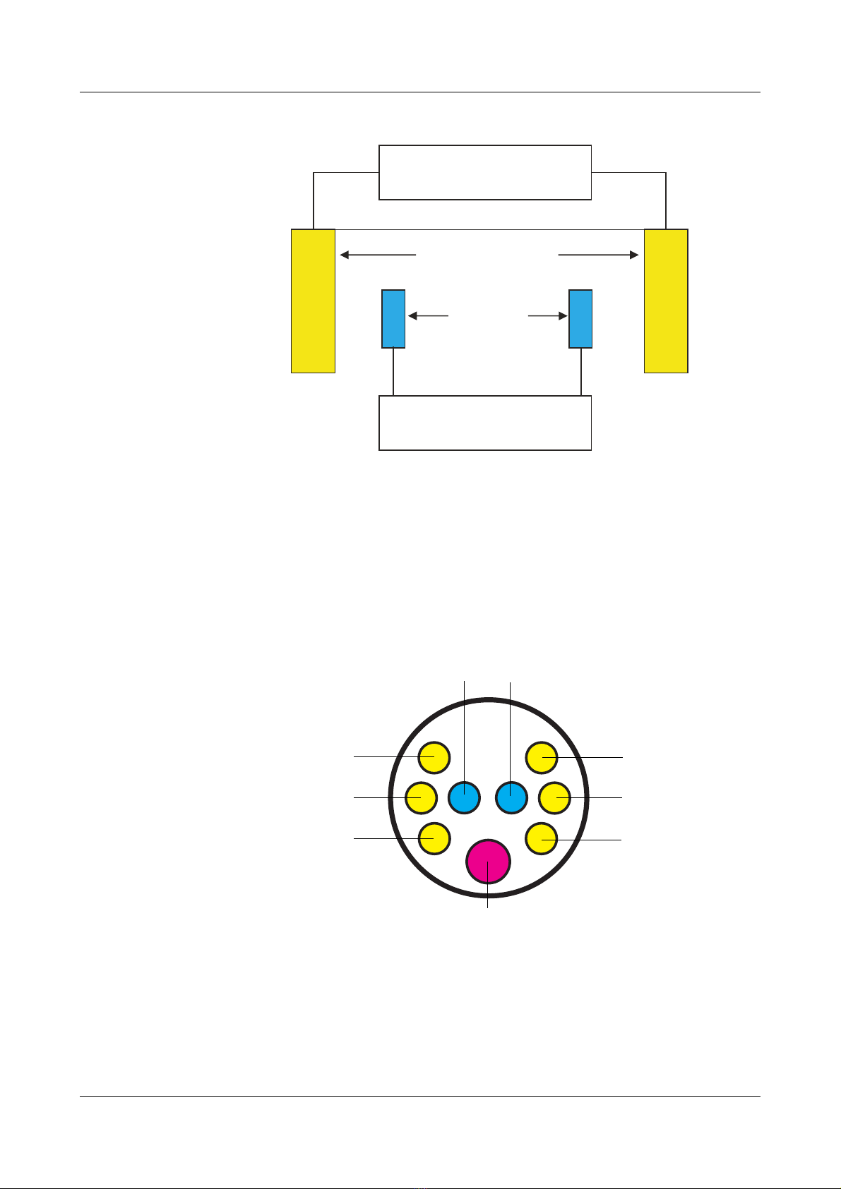
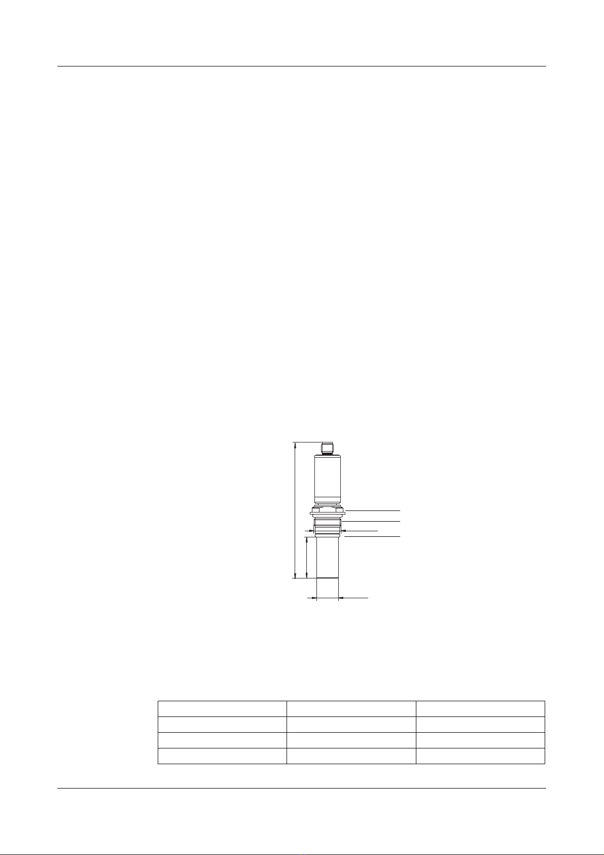
Stainless steel electrodes are inserted into a circular, plastic body. The process
seal provided as standard is an EPDM O-ring. A fast-response temperature
probe delivers information about the process temperature to the measurement
amplifier. Electrical connection is made via an M12 connector.
The measuring sensor is available in three fitting lengths, for optimum
installation in different pipe diameters. The measuring sensor can also be
installed in container walls. No incident flow is required to make it work, but is
recommended for fast, stable measurement values and to prevent the
accumulation of deposits.
A certificate of quality is included among the items supplied (exact cell
constant, FDA approval for the material, typical surface roughness, etc.).
Operative range
Their vast measuring range of 1 µS/cm to 600 mS/cm, allows the sensors to
be used in washing processes in food and drink applications, pharmaceuticals
and biotechnology, where the different conductivities have to be safely
recorded by a measuring system (e.g. CIP/SIP applications, reverse processes
in ion exchangers, phase separation, bottle cleaning plants, process water).
Note
Used in combination with the JUMO AQUIS 500 CR transmitter/controller, as
per data sheet 202565 and JUMO PEKA process connection adapters as per
data sheet 409711.
Key features
• Vast measuring range
• EHEDG-certified process connections (clamp, Varivent®, aseptic NKS)
• CIP/SIP capability
• Design complies with EHEDG and FDA standards
• Certificate of quality included

7
2 Description
Function
The measuring sensors have two pairs of electrodes. The transmitter applies
alternating current at the outer pair of electrodes. A voltage is released at the
inner electrodes - subject to the conductivity of the measuring material. The
transmitter acquires the voltage and uses it to calculate the electrolytic
conductivity value. Functionally, excitation and measurement are kept
separate. This has some advantages compared to 2-electrode measuring
sensors, as the effects of polarization recede into the background. To a large
extent, incoming resistances are automatically compensated. Measurement
errors as a result of contamination or deposits, are reduced.
Measuring sensors
voltage/current
voltage
current/voltage
control
voltage measurement
(1) (4)
(2) (3)
Description M12 connector pin
(1) Current supply, outer electrode 1 6
(2) Voltage tap, inner electrode 1 7
(3) Voltage tap, inner electrode 2 3
(4) Current supply, outer electrode 2 4
(5) Pt1000 temperature probe 1, 2 and 5
(2) (3)
(4)
(4)
(1)
(4)
(1)
(1)
(5)

8
3 Instrument identification
3.1 Nameplate
On the measuring sensor
3.2 Type description
The date of manufacture is encoded in "F-Nr." (serial number):
0942 means year of manufacture 2009/calendar week 42.
JUMO GmbH & Co. KG
Fulda, Germany www.jumo.net
Typ: 202930/10-1005-997-83/000
VARTN: 20/00123456
F-Nr.: 01234567 01 0 0942 0002
Cell M: 0,30 1/cm
(1) Basic type
202930 JUMO tecLine CR-4P
Conductive 4-electrode conductivity sensor
(2) Basic type extension
10 Short design
20 Medium design
30 Long design
(3) Temperature compensation
1005 Pt1000
(4) Electrode material
31 Stainless steel 1.4435 (316L)
(5) Process connection1
1Process connection adadpters (see "Accessories") must be ordered separa-
tely.
997 JUMO PEKA
(6) Electrical connection2
2The CR-4P cable is required for electrical connection (see "Accessories")!
83 M12 connector
(7) Extra codes
000 none
(1) (2) (3) (4) (5) (6) (7)
Order code /- ---/
Sample order 202930 / 10 - 1005 - 31 - 997 - 83 / 000

9
3 Instrument identification
3.3 Accessories
Designation Sales No.
CR-4P cable, 5 m, made up, with M12 connector 00528699
CR-4P cable, 10 m, made up, with M12 connector 00528700
JUMO PEKA process
connection adapter for Material Sales No.
Varivent DN 40-125 Stainless steel 1.4435/316L 00445046
Varivent DN 40-125 Stainless steel 1.4435/316L;
Ra < 0,8 µ
with certificate EN 10204-3.1
00577961
Clamp DN 25/32/40 Stainless steel 1.4435/316L 00445047
Clamp DN25/32/40 Stainless steel 1.4435/316L;
Ra < 0,8 µ
with certificate EN 10204-3.1
00577998
Clamp DN 50 Stainless steel 1.4435/316L 00445037
Clamp DN 50 Stainless steel 1.4435/316L;
Ra < 0,8 µ
with certificate EN 10204-3.1
00577997
Aseptic DN 40 Stainless steel 1.4435/316L 00446458
Aseptic DN 40 Stainless steel 1.4435/316L;
Ra < 0,8 µ
with certificate EN 10204-3.1
00577995
Aseptic DN 50 Stainless steel 1.4435/316L 00445035
Aseptic DN 50 Stainless steel 1.4435/316L;
Ra < 0,8 µ
with certificate EN 10204-3.1
00577979
Aseptic NKS DN 40 Stainless steel 1.4435/316L 00447555
Aseptic NKS DN 40 Stainless steel 1.4435/316L;
Ra < 0,8 µ
with certificate EN 10204-3.1
00577999

10
4 Mounting
4.1 General
Mounting location
Find a location that ensures easy accessibility for the later calibration.
The fastening must be secure and must ensure low vibration for the instrument.
The operating conditions (temperature, pressure, chemical composition of the
measuring material, etc.,) must not be allowed to damage the measuring sensor.
The measuring sensor must not be modified mechanically (e.g. shortened,
drilled, ground).
A minimum distance of at least two meters must be maintained when
installing several JUMO tecLine CR-4P type conductivity sensors.
Installation position
The conductivity sensor can be mounted in any position. But it is essential to
make sure that the measuring sensor electrodes are fully immersed in the
measuring material.
Incident flow
No incident flow is required to make the conductivity sensor work, but is
recommended for fast, stable measurement values and to prevent the
accumulation of deposits. Structural measures must be taken to prevent flow
separation or gas bubbles in the measuring material.
Immersion length
The immersion length (EL) of the conductivity sensor must be in keeping with
the installation situation.
(1) Width across flats 27
(2) JUMO PEKA process connection
A suitable process connection adapter is an essential requirement of
installation, see below.
(3) 21 × 2.5 O-ring (EPDM)
Immersion length EL Total length GL Type
18 126 202930/10
38 146 202930/20
48 156 202930/30
M28x1.5
ø22.5
GL
EL
(1)
(2)
(3)

11
4 Mounting
4.2 JUMO PEKA process connection adapter
The EHEDG-certified system for process connection – JUMO PEKA – allows it
to be used in pharmaceutical and food technology without difficulty. JUMO
PEKA is an adapter system that combines the measuring sensor with the
process connection. All the materials are physiologically safe, and meet FDA
standards.
4.3 Mounting suggestions
Varivent®
(1) JUMO PEKA process connection adapter
Varivent®DN 40-125, sales no.: 00445046
(2) JUMO tecLine CR-4P conductivity sensor.
(3) The Varivent®housing DN xx
is not supplied by JUMO and must be provided by the customer!
Varivent housing DN Diameter D L Type
40 38 3 202930/10
50 50 9
65 66 18
80 81 24.5
100 100 34
øD
ø68
L
18
21.5
(2)
(1)
(1)
(3)
(3)

4 Mounting
12
Clamp
(1) JUMO PEKA process connection adapter
(1a) Clamp DN 25/32/40, sales no.: 00445046
(1b) Clamp DN 50, sales no.: 00445037
(2) JUMO tecLine CR-4P conductivity sensor.
(3) The DN xx clamp adapter, DIN 32676
is not supplied by JUMO and must be provided by the customer!
(4) The clamp DN xx T-piece, DIN short, similar to DIN 11852
is not supplied by JUMO and must be provided by the customer!
Clamp
adapter DN T-piece
DN Diamter
DDiamter
D1 LType
25 32-25 32 26 5 202930/20
40-25 38 0 202930/30
50-25 50 7
65-25 66 15
80-25 81 20
100-25 100 30
50 65-50 66 50 15
80-50 81 20
100-50 100 30
21.5
ø50.5
øD1
øD
L
21.5
ø64
(2)
(1a)
(1)
(3)
(1b)
(4)

13
4 Mounting
Aseptic
(1) JUMO PEKA process connection adapter
(1a) Aseptic DN 40, sales no.: 00446458
(1b) Aseptic DN 50, sales no.: 00445035
(2) JUMO tecLine CR-4P conductivity sensor.
(3) The DN xx threaded adapter, DIN 11864
is not supplied by JUMO and must be provided by the customer!
(4) The DN xx T-piece
is not supplied by JUMO and must be provided by the customer!
Threaded
adapter T-piece
DN Diameter
DDiameter
D1 LType
40 50-40 50 38 10 202930/30
65-40 66 18
80-40 81 27
100-40 100 37
50 65-50 66 50 18
80-50 81 27
100-50 100 37
øD
L
2525
ø67
ø55
øD1
(2)
(1a)
(1)
(4)
(1b)
(3)

4 Mounting
14
Aseptic NKS
(1) JUMO PEKA process connection adapter
Aseptic NKS DN 40, sales no.: 00447555
(2) JUMO tecLine CR-4P conductivity sensor.
(3) Collar clamp adapter NKS DN 40, Form A, DIN 11864-3
is not supplied by JUMO and must be provided by the customer!
(4) The DN xx T-piece
is not supplied by JUMO and must be provided by the customer!
Collar
clamp
adapter
T-piece
DN Diameter
DDiameter
D1 LType
NKS
DN 40
Form A
50-40 50 38 10 202930/30
65-40 66 18
80-40 81 27
100-40 100 37
25
øD1
øD
ø64
L
(2) (1)
(1)
(4)
(3)

15
5 Installation
5.1 Electrical connection
• Lay the input, output, and supply lines so they are physically separated
from each other and are not parallel
• If possible, use the CR-4P cable (see Accessories) to connect the
conductivity sensor; do not lay the connecting cable close to components
or lines through which current is flowing
• The cables must have an uninterrupted run (do not route them via terminal
blocks or similar arrangements)
• No other consumers can be connected to the power terminals of the
instrument
• The conductivity sensor is not suitable for installation in areas with an
explosion hazard
• It is essential to comply with the electrical connection instructions in the
operating manual of the transmitter that is being used
• Apart from faulty installation, incorrect settings on the transmitter may also
affect the proper functioning of the subsequent process or lead to damage;
you should therefore always provide safety equipment that is independent
and it should only be possible for qualified personnel to make settings
5.2 Terminal assignment and wiring colors
Incorrect connection of the conductivity sensor will produce
inaccurate measurement results!
Connection for M12 connector CR-4P cable
Pin Assignment Color
Pt1000 temperature probe
for temperature compensation
1
2
5
GN
YE
BN
Voltage tap inner electrode 2 3 PK
Current entry outer electrode 2 4 BL
Current entry outer electrode 1 6 RD
Voltage tap inner electrode 1 7 GR
NC
Warning: The shielding of the cable has to be connected to the transmitter only – not to the
sensor!
ϑ
1
2
5
1
7
6
5
2
8
3
4

5 Installation
16
5.3 CR-4P cable
Use only the CR-4P cable for conductivity sensor connection:
• CR-4P cable, 5 m, made up, with M12 connector
Sales no.: 00528699
• CR-4P cable, 10 m, made up, with M12 connector
Sales no.: 00528700
For metrological reasons, the maximum cable length is limited to 10 m!
M12 cable socket: metal, 8-pin
Cable diameter: 7.5 mm
Cable material: PUR, blue
Ambient temperature: -30 to +80 °C
Cable length: 5 m or 10 m
YE
ø7.5
GN
BN
WH
BL
GR
PK
RD

17
5 Installation
5.4 Connection example
Cable routing in he transmitter
✱Run the connecting cables through the JUMO AQUIS 500 CR cable glands.
✱Locate the measuring lead as shown in the diagram.
Fasten the measuring lead to the screen with the clip (3).
✱Connect the wires, as shown below.
✱Connect the pluggable screw terminals of row 1 (1) and row 2 (2) to the
instrument slots.
This example is only valid for connecting the JUMO tecLine CR-
4P conductivity sensor to a JUMO AQUIS 500 CR transmitter/
controller for conductivity!
(1)
(2)
(3)

5 Installation
18
Measuring sensor connection
Terminal assignment
Terminal 1 - RD
Terminal 2 - GR
Terminal 3 - PK
Terminal 4 - BL
Terminal 8 - YE
Terminal 9 - GN
Terminal 10 - BN
Connection of JUMO dTRANS CR 02
ϑ
Resistance thermometer
SC = shield
Row 1
Row 2
Conductivity sensor
(1) Row 1 (a) Option 1 (b) Option 2 (c) Option 3
(2) Row 2 Main input board
(conductivity/resistance/temperature/standard signal)
(3) Row 3 PSU board
(power supply/2× relays)
1
2
3
4
1
2
3
4
5
6
7
8
6
7
8
9
10
9
10
11
12
4
L1(L+)
5
6
8
9
11
12
13
15
16
17
N(L-)
11
12
13
14
15
(a)
(b)(c)
(1)
(3)
(2)

19
6 Calibration
6.1 Notes
6.2 General
JUMO tecLine CR-4P conductivity sensors are exactly gaged at the factory.
The cell constant of every measuring sensor is documented both on the cell
stem and on the calibration certificate that is also supplied.
This cell constant should be entered directly into the connected transmitter
(e. g. JUMO AQUIS 500 CR).
In combination with the JUMO AQUIS 500 CR, measuring accuracy in the
20 µS/cm to 600 mS/cm range is better than 5 %. To achieve far greater
measuring accuracy, calibrate the transmitter close to its later working point.
To monitor and increase the quality of measurement, the conductivity
measurement chain (conductivity sensor + connecting cable + transmitter)
should be regularly calibrated.
Reference solutions
It is advisable to use one of the following reference solutions for calibration:
• ASTM D 1125, reference solution B: 0.1 N KCl with 12856 µS/cm
• DIN 38404, Part 8, Section 8.3: 0.1 mol/l KCl with 12.95x10³µS/cm
However, any calibration solution in the medium conductivity range can also
be used.
6.3 JUMO AQUIS 500 CR settings
The following settings are the minimum that have to be made:
• Cell type (type of connection): 4-electrode or 4-wire
• Nominal cell constant 1.0 1/cm
• Relative cell constant as % (see sensor nameplate or
certificate)Einstellungen am JUMO dTRANS CR 02
Ageing and contamination (deposits) can cause the cell constant
of the conductivity sensor to change.
The transmitter should therefore be calibrated to the connected
conductivity sensor at regular intervals (subject to the measuring
material and the operating conditions)!
It is essential to comply with the JUMO AQUIS 500 CR operating
instructions (B 202565.0)!

20
7 Maintenance/troubleshooting
7.1 Cleaning the conductivity sensor
• Light contamination can be wiped off with a soft, cleansing tissue, or similar
• Wash off sticky contamination or greasy and oily contamination with a hot
rinsing agent solution and a soft cloth or soft brush; Ethanol can also be
used to clean the sensor, if necessary
• Diluted hydrochloric acid (3 % by weight) can also be used to dissolve the
contamination in the event of calciferous coatings or precipitated metal
hydroxides or metal oxides
• If none of the methods mentioned above remove the contamination, other
solvents, acids or caustic solutions may be used, with the aid of ultrasonic
baths where required;
in this case, it is necessary to ensure that the conductivity sensor
components are resistant to the cleaning agents being used, see section 8
"Technical data"
Conductive conductivity sensors are not authorized for use in
highly adherent, oily or glutinous media - we recommend using our
inductive conductivity measuring instruments here!
After cleaning the conductivity sensor, always rinse it with water!
The conductive conductivity sensor electrodes are in direct
contact with the measurement medium. Regular cleaning must
therefore be performed, relative to the contamination
susceptibility of the measuring material!
Abrasive cleaners have limited suitability! The measurement
electrodes must not be damaged!
Table of contents
Other JUMO Accessories manuals

JUMO
JUMO digiLine CR Series User manual

JUMO
JUMO BlackLine CR 4P User manual

JUMO
JUMO tecLine ClO2 User manual

JUMO
JUMO tecLine Series User manual

JUMO
JUMO 902454/10 User manual

JUMO
JUMO MAERA S29 SW User manual

JUMO
JUMO tecLine ClO2 User manual

JUMO
JUMO digiLine O-DO S10 User manual

JUMO
JUMO 201040 User manual