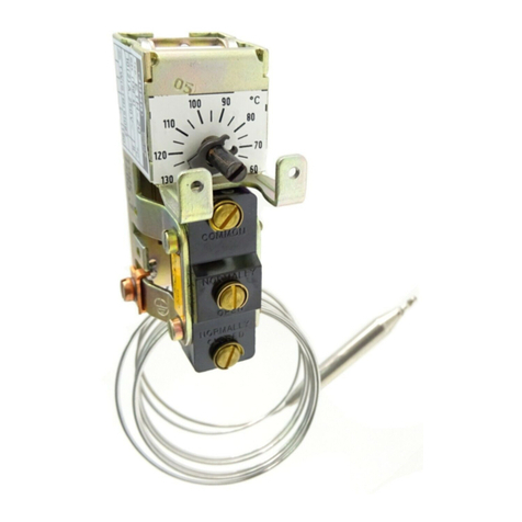
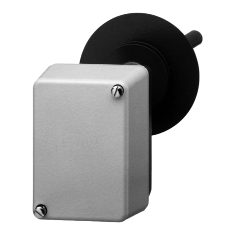
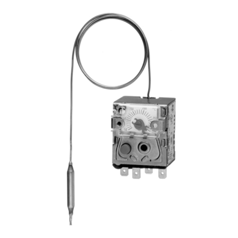
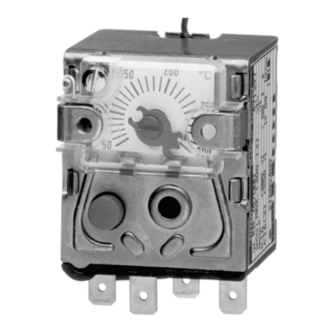
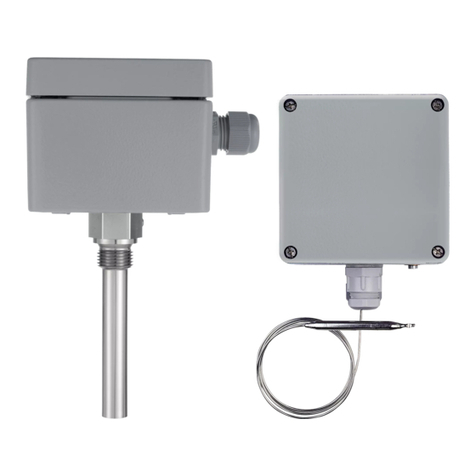
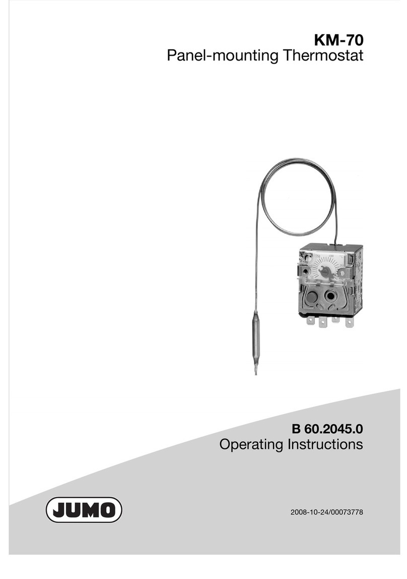
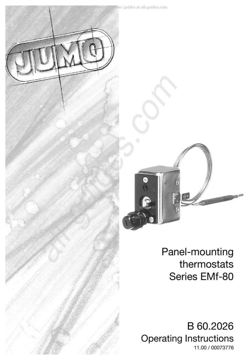
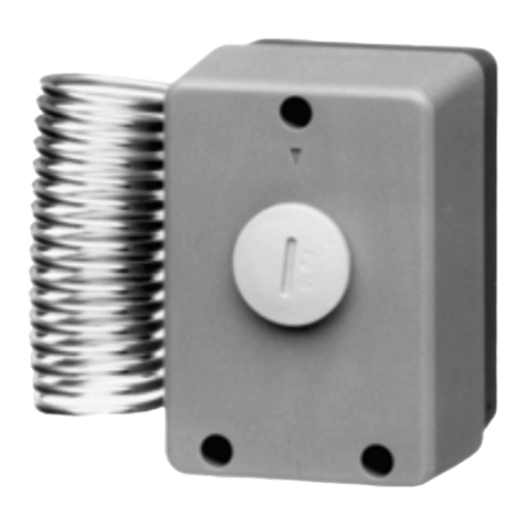
JUMO EM Series User manual

60202100T90Z003K000
V4.00/EN/00073772/2022-02-02
Panel-mounted thermostats
EM Series
with 1, 2, 3, or 4 single-pole snap-action switches
PEDPressure
Equipment
Directive
®
Operating Manual


Contents
Contents
1 Safety information. . . . . . . . . . . . . . . . . . . . . . . . . . . . . . . . . . . . . . . . . . . . 5
1.1 Warning symbols. . . . . . . . . . . . . . . . . . . . . . . . . . . . . . . . . . . . . . . . . . . . . . . . . . . . . . . . . .5
1.2 Note symbols . . . . . . . . . . . . . . . . . . . . . . . . . . . . . . . . . . . . . . . . . . . . . . . . . . . . . . . . . . . .5
2 Introduction . . . . . . . . . . . . . . . . . . . . . . . . . . . . . . . . . . . . . . . . . . . . . . . . . 6
2.1 Brief description . . . . . . . . . . . . . . . . . . . . . . . . . . . . . . . . . . . . . . . . . . . . . . . . . . . . . . . . . .6
2.2 Intended use . . . . . . . . . . . . . . . . . . . . . . . . . . . . . . . . . . . . . . . . . . . . . . . . . . . . . . . . . . . . .6
2.3 Identification marking . . . . . . . . . . . . . . . . . . . . . . . . . . . . . . . . . . . . . . . . . . . . . . . . . . . . . .7
3 Identifying the device version . . . . . . . . . . . . . . . . . . . . . . . . . . . . . . . . . . 8
3.1 Nameplate. . . . . . . . . . . . . . . . . . . . . . . . . . . . . . . . . . . . . . . . . . . . . . . . . . . . . . . . . . . . . . .8
3.2 Order details . . . . . . . . . . . . . . . . . . . . . . . . . . . . . . . . . . . . . . . . . . . . . . . . . . . . . . . . . . . . .8
4 Mounting . . . . . . . . . . . . . . . . . . . . . . . . . . . . . . . . . . . . . . . . . . . . . . . . . . . 12
4.1 Dimensions . . . . . . . . . . . . . . . . . . . . . . . . . . . . . . . . . . . . . . . . . . . . . . . . . . . . . . . . . . . . . .12
4.2 Fixing the panel-mounted thermostat . . . . . . . . . . . . . . . . . . . . . . . . . . . . . . . . . . . . . . . . . .16
4.2.1 Mounting the switching head . . . . . . . . . . . . . . . . . . . . . . . . . . . . . . . . . . . . . . . . . . . . . . . .16
4.3 Capillary, temperature probe and thermowell . . . . . . . . . . . . . . . . . . . . . . . . . . . . . . . . . . . .17
4.3.1 General information . . . . . . . . . . . . . . . . . . . . . . . . . . . . . . . . . . . . . . . . . . . . . . . . . . . . . . .17
4.3.2 Approved process connections. . . . . . . . . . . . . . . . . . . . . . . . . . . . . . . . . . . . . . . . . . . . . . .18
4.4 Permissible pressure at the thermowell . . . . . . . . . . . . . . . . . . . . . . . . . . . . . . . . . . . . . . . .19
4.4.1 Thermowells 20, 22/23, 40, and 41/42 . . . . . . . . . . . . . . . . . . . . . . . . . . . . . . . . . . . . . . . . .19
5 Installation . . . . . . . . . . . . . . . . . . . . . . . . . . . . . . . . . . . . . . . . . . . . . . . . . . 23
5.1 Installation notes. . . . . . . . . . . . . . . . . . . . . . . . . . . . . . . . . . . . . . . . . . . . . . . . . . . . . . . . . .23
5.2 Electrical connection . . . . . . . . . . . . . . . . . . . . . . . . . . . . . . . . . . . . . . . . . . . . . . . . . . . . . . .23
5.3 Connection diagram . . . . . . . . . . . . . . . . . . . . . . . . . . . . . . . . . . . . . . . . . . . . . . . . . . . . . . .25
6 Settings . . . . . . . . . . . . . . . . . . . . . . . . . . . . . . . . . . . . . . . . . . . . . . . . . . . . 26
6.1 Unlocking the TB or STB . . . . . . . . . . . . . . . . . . . . . . . . . . . . . . . . . . . . . . . . . . . . . . . . . . .26
6.2 Setpoint adjustment . . . . . . . . . . . . . . . . . . . . . . . . . . . . . . . . . . . . . . . . . . . . . . . . . . . . . . .27
6.3 Self-monitoring on the STB and STW (STB) . . . . . . . . . . . . . . . . . . . . . . . . . . . . . . . . . . . .28
6.4 Use of the STW (STB) as STB . . . . . . . . . . . . . . . . . . . . . . . . . . . . . . . . . . . . . . . . . . . . . . .28
7 Technical data . . . . . . . . . . . . . . . . . . . . . . . . . . . . . . . . . . . . . . . . . . . . . . . 29
7.1 Control ranges and probe table . . . . . . . . . . . . . . . . . . . . . . . . . . . . . . . . . . . . . . . . . . . . . .29
7.2 Control ranges and temperature probes . . . . . . . . . . . . . . . . . . . . . . . . . . . . . . . . . . . . . . . .30
7.3 Capillary and temperature probe . . . . . . . . . . . . . . . . . . . . . . . . . . . . . . . . . . . . . . . . . . . . .30

Contents
7.4 Electrical data . . . . . . . . . . . . . . . . . . . . . . . . . . . . . . . . . . . . . . . . . . . . . . . . . . . . . . . . . . . .31
7.5 Operating data . . . . . . . . . . . . . . . . . . . . . . . . . . . . . . . . . . . . . . . . . . . . . . . . . . . . . . . . . . .32
7.6 Housing. . . . . . . . . . . . . . . . . . . . . . . . . . . . . . . . . . . . . . . . . . . . . . . . . . . . . . . . . . . . . . . . .34
7.7 Process connection. . . . . . . . . . . . . . . . . . . . . . . . . . . . . . . . . . . . . . . . . . . . . . . . . . . . . . . .34
7.8 Approvals and approval marks . . . . . . . . . . . . . . . . . . . . . . . . . . . . . . . . . . . . . . . . . . . . . . .34
8 Maintenance, cleaning and returns . . . . . . . . . . . . . . . . . . . . . . . . . . . . . . 36
8.1 Maintenance . . . . . . . . . . . . . . . . . . . . . . . . . . . . . . . . . . . . . . . . . . . . . . . . . . . . . . . . . . . . .36
8.2 Cleaning . . . . . . . . . . . . . . . . . . . . . . . . . . . . . . . . . . . . . . . . . . . . . . . . . . . . . . . . . . . . . . . .36
8.3 Returns . . . . . . . . . . . . . . . . . . . . . . . . . . . . . . . . . . . . . . . . . . . . . . . . . . . . . . . . . . . . . . . . .36
9 Declaration of conformity. . . . . . . . . . . . . . . . . . . . . . . . . . . . . . . . . . . . . . 37
10 China RoHS . . . . . . . . . . . . . . . . . . . . . . . . . . . . . . . . . . . . . . . . . . . . . . . . . 42

5
1 Safety information
1 Safety informat ion
1.1 Warning symbols
WARNING!
This symbol in connection with the signal word indicates that personal injury may occur if the respective
precautionary measures are not carried out.
CAUTION!
This symbol in connection with the signal word indicates that material damage or data loss will occur
if the respective precautionary measures are not taken.
1.2 Note symbols
NOTE!
This symbol refers to important information about the product, its handling, or additional benefits.
READ THE DOCUMENTATION!
This symbol, which is attached to the device, indicates that the associated documentation for the de-
vice must be observed. This is necessary to identify the nature of the potential hazard, and to take
measures to prevent it.
DISPOSAL!
At the end of its service life, the device and any batteries present do not belong in the trash! Please en-
sure that they are disposed of properly and in an environmentally friendly manner.

6
2 Introduction
2 Introduction
2.1 Brief description
Thermostats control and monitor thermal processes. The devices of the EM series are available as tem-
perature controllers TR, temperature monitors TW, temperature limiters TB, safety temperature monitors
STW (STB), and safety temperature limiter STB. In the event of a malfunction, the STB switches the
monitored machine to a safe operating status.
Panel-mounted thermostats operate according to the fluid expansion principle – a microswitch is used
as an electrical switching element.
Switching functions
Temperature controller TR, temperature monitor TW, and safety temperatur monitor STW
If the temperature on the temperature probe exceeds the setpoint value, the electrical circuit is opened
or closed by a microswitch. If the temperature falls below the selected setpoint value (by the switching
differential), the microswitch is reset to its initial position.
Temperature limiter TB and safety temperature limiter STB
If the temperature at the temperature sensor exceeds the set limit value, the electrical circuit is opened
or closed by a microswitch.
After the temperature has fallen below the limit value by approx. 10 % of the scale range (approx. 15 %
with setpoint setting >350 °C), the microswitch can be unlocked manually.
For set points above 120 °C, the set point adjusted on the STB must be secured against adjustment (e.g.
with a lead seal).
Self-monitoring for safety temperature limiter STB and safety temperature monitor STW (STB)
If the measuring system is destroyed (i.e. if the expansion fluid escapes) the pressure in the membrane
of the STB and STW (STB) drops and permanently opens the electrical circuit. Unlocking is then no lon-
ger possible.
When the STW (STB) and STB sensors cools down to the negative temperature range, the circuit 1 to 2
opens, but must be unlocked manually by the restart knob when the temperature rises. The STW (STB)
restarts automatically.
Use of the safety temperature monitor STW as a safety temperature limiter STB
The circuitry used with the thermostat must comply with DIN EN 14597 and VDE 0631.
2.2 Intended use
Versions according to DIN EN 14597:
• Temperature controller TR
• Temperature monitor TW
• Temperature limiter TB
• Safety temperature monitor STW (STB)
• Safety temperature limiter STB
Type examination according to:
• DIN EN 14597
• Pressure Equipment Directive (only for types EM-20, EM-30, EM-40, EM-50)
•UL

7
2 Introduction
You will find the Declarations of conformity at www.jumo.en.
• Products
• Temperature
• Monitor/Limiter
• Electromechanical
• Panel-mounting thermostats 602021
• Documentation
• Declaration of conformity/White Paper
Ask for them to be sent.
CAUTION!
Failure of the device
Cutting or kinking the capillary of the device leads to permanent failure of the functions!
Physical and toxicological properties of the expansion fluid that may escape in the event of a system
fracture.
NOTE!
At present, there is no restrictive statement from the health authorities concerning any danger to health
over short periods and at low concentration, e.g. after a fracture of the measuring system.
2.3 Identification marking
Depending on the version (for details see nameplate):
Control range
with end of scale
Dangerous
reactions
Fire and explosion hazard Water
contamination
Toxicological data
Ignition
temperature
Explosion limit Irritant Danger
to health
Toxic
< 200 °C No 355 °C 0.6 to 8 % v/v Yes Yes See note No
≥200°C
≤350°C
No 490 °C - Yes Yes See note No
>350°C
≤500°C
No No No No No No No
PEDPressure
Equipment
Directive
®

8
3 Identifying the device version
3 Identi fying t he device version
3.1 Nameplate
Exemplary marking on the device housing:
3.2 Order details
(1) Type
(2) Order code
(3) Regulating or limit value range/ambient temperature at which this thermostat was calibrated (op-
tion)
(4) Switching capacity
(5) Permissible ambient temperature
(6) Fabrication number
(7) Year of manufacture
(8) Week of manufacture
(5)
(3)
(4)
(2)
(1)
(6)
(4)
(8)
(7)
(1) Basic type
603031 Panel-mounted thermostats, EM Series
(2) Basic type extensions
0001 EM-1 Temperature controller (TR), 1-pole
0002 EM-2 Temperature monitor (TW), 1-pole
0003 EM-3 Temperature monitor (TW), permanently set, 1-pole
0004 EM-4 Temperature limiter (TB), permanently set, 1-pole
0005 EM-5 Temperature limiter (TB, 1-pole
0013 EM-13 Temperature controller (TR/TW), 2-pole
0014 EM-14 Temperature controller (TR/TB), 2-pole
0020 EM-20 Safety temperature monitor (STW (STB))
0023 EM-23 Temperature monitor (TR/TB), 2-pole
0024 EM-24 Temperature monitor (TW/TB), 2-pole
0030 EM-30 Safety temperature monitor (STW (STB)), permanently set
0033 EM-33 Temperature monitor (TW/TW), 2-pole
0040 EM-40 Safety temperature limiter (STB), permanently set
0044 EM-44 Temperature limiter (TB/TB), 2-pole
0050 EM-50 Safety temperature limiter (STB)
0054 EMF-54 Temperature limiter (TB/TB), 2-pole

9
3 Identifying the device version
0133 EMF-133 Temperature controller (TR/TW/TW), 3-pole
0134 EMF-134 Temperature controller (TR/TW/TB), 3-pole
0233 EMF-233 Temperature monitor (TW/TW/TW), 3-pole
0333 EMF-333 Temperature monitor (TW/TW/TW), 3-pole
0444 EMF-444 Temperature limiter (TB/TB/TB), 3-pole
0544 EMF-544 Temperature limiter (TB/TB/TB), 3-pole
1333 EMF-1333 Temperature controller (TR/TW/TW/TW), 4-pole
2333 EMF-2333 Temperature monitor (TW/TW/TW/TW), 4-pole
3333 EMF-3333 Temperature monitor (TW/TW/TW/TW), 4-pole
(3) Control range (TW)
000 For permanently set limit value
013 -20 to +40 °C
021 0 to 50 °C
025 0 to 100 °C
027 0 to 150 °C
028 0 to 200 °C
041 20 to 90 °C
045 20 to 400 °C
046 20 to 500 °C
052 30 to 110 °C
062 50 to 200 °C
063 50 to 250 °C
064 50 to 300 °C
075 75 to 100 °C
085 85 to 110 °C
090 120 to 150 °C
091 160 to 200 °C
092 210 to 300 °C
094 250 to 300 °C
095 300 to 400 °C
096 350 to 500 °C
(4) Limit value (STW/STB)
000 For adjustable control range
100 100 °C
95 95 °C
(5) Switching differential
00 None
With liquid-filled measuring system
10 1 % Only with TR and TW
25 2.5 % Only with TR and TW
50 5 % Only with TR, TW and STW
70 7 % Only with TR, TW and STW
With gas-filled measuring system
30 3 % Only with TR and TW
50 5 % Only with TR, TW and STW
60 6 % Only with TR and TW

3 Identifying the device version
10
01 10 % Only with TR and TW
(6) Capillary length
0 None
1000 1,000 mm
2000 2,000 mm
3000 3,000 mm
4000 4,000 mm
5000 5,000 mm
(7) Capillary material
20 CrNi (stainless steel)
40 Cu (copper)
(8) Process connection
10 Plain cylindrical probe
20 Screw-in protection tube
(9) Thread of process connection
00 None
13 G 1/2
(10) Process connection material
00 None
20 CrNi (stainless steel)
40 CuZn (brass)
(11) Insertion length
000 None
100 100 mm
120 120 mm
150 150 mm
200 200 mm
300 300 mm
(12) Protection tube diameter
00 None
10 10 mm
88mm
(13) Probe diameter
66mm
88mm
(14) Extra codes
000 None
025 Central mounting M10 × 1, metall
574 Microswitch with N/C contact, restart lock, and additional signal contact (only for TB and STB)
699 Screw connection up to 2.5 mm²
702 Snap-action contact, gold-plated
704 Switching head mounting with 2 M4 screws, spaced 28 mm
705 Switching head mounting with 2 M3 screws, spaced 33 mm
707 Temperature compensation
710 Central mounting M10 × 1, standard

11
3 Identifying the device version
950 Railway application
(1) (2) (3) (4) (5) (6) (7) (8)
Order code /-------
Order example 602021 / 0005 - 052 - 000 - 00 - 2000 - 40 - 10 -
(9) (10) (11) (12) (13) (14)
- - - - / , ...a
00 - 00 - 000 - 00 - 6 / 574
aList extra codes in sequence, separated by commas.

12
4 Mounting
4 Mounting
4.1 Dimensions
EM-1, EM-2, EM-3, EM-4, EM-5
(1)
2
1
4
(3)
A
(2)
38
6
G
21
15
21
B
°C 250°
29
52
3
Ød
Ø1.5
18
4.6
L
6Ø
36.5
46
~
(1) Restart knob only with abbreviation 4 and 5
(2) Not applicable with abbreviation 2, 3, 4, 5
(3) Tab connector DIN 46244-A6,3-0,8
(A) Rear view

13
4 Mounting
EM-13, EM-14, EM-20, EM-23, EM-24, EM-30, EM-33, EM-40, EM-44, EM-50, EMF-54
(1)
(3)
A
III
1
1
44
2
2
(2)
G
21
15
21
B
°C 250°
11
38
52
3
Ø d
Ø1.5
4.6
L
6
Ø
46
36.5
18
~
(1) Restart knob only with abbreviation 40, 44, 50 and 5
(2) Not applicable with abbreviation 2, 3, 4, 5, 20, 30, 40 and 50
(3) Tab connector DIN 46244-A6,3-0,8
(A) Rear view

4 Mounting
14
EMF-133, EMF-134, EMF-233, EMF-234, EMF-333, EMF-444, EMF-544
(1)
(3)
A
I
III
1
1
44
2
2
II
1
4
2
(2)
G
21
15
21
B
°C 250°
19
38
52
3
54
Ø d
Ø 1.5
4.6
L
6
Ø
46
36.5
18
~
(1) Restart knob only with abbreviation 444, 544
(2) Not applicable with abbreviation 2, 3, 4, 5
(3) Tab connector DIN 46244-A6,3-0,8
(A) Rear view

15
4 Mounting
EMF-1333, EMF-2333, EMF-3333
(1)
(3)
A
I
IV
1
1
44
2
2
II
1
4
2
III
1
4
2
(2)
G
21
15
21
B
°C 250°
27
38
3
52
70
Ød
Ø 1.5
4.6
L
6
Ø
46
36.5
18
~
(1) Restart knob only with abbreviation 4444
(2) Not applicable with abbreviation 2, 3, 4, 5
(3) Tab connector DIN 46244-A6,3-0,8
(A) Rear view
BG
Standard 22 M3
Extra code 704 28 M4
Extra code 705 33 M3
Screw connection EM-1, extra code 699

4 Mounting
16
4.2 Fixing the panel-mounted thermostat
4.2.1 Mounting the switching head
EM-1
Mounting the switching head with 2 screws M3 on chassis (M4 with extra code 704).
EM-2, EM-3, EM-4, EM-5, EM-20, EM-30, EM-30, EM-40, EM-44, EM-50, EMF-54, EMF-444, EMF-544
Mounting the switching head with 2 screws M3 on chassis (M4 with extra code 704).
Operating position Any
Dim. (mm)
GB
Standard 3,5 22
Extra code 704 4,5 28
Extra code 705 3,5 33
(1) Screw
(2) Panel
(1)
(1)
(2)
Dim. (mm)
XY
EM-2, EM-3, EM-20, EM-30 - -
EM-4, EM-5 15 6
EM-40, EM-50 15 11
EM-44, EMF-54 15 11
EMF-444, EMF-544 15 19
GB
Standard 3,5 22
Extra code 704 4,5 28
Extra code 705 3,5 33
(1) Screw
(2) Panel
(1)
(1) (2)

17
4 Mounting
EM-4, EM-5, EM-40, EM-50 with central mounting
Extra code 710
4.3 Capillary, temperature probe and thermowell
4.3.1 General information
CAUTION!
Failure of the device
Cutting or kinking the capillary of the device leads to permanent failure of the functions!
The minimum permissible bending radius of the capillary is 5 mm.
The temperature probe must be mounted in a JUMO thermowell, otherwise the approval of the device
becomes invalid.
NOTE!
The temperature probe must be completely immersed in the medium to be measured. The temperature
probe or protection tube must not come into contact with the walls of the container or pipe.
To ensure their overall accuracy, the thermostats must only be used together with the pockets supplied
by the factory (diameter D = 8 or 10 mm).
Thermowells with diameter D = 10 mm may only be fitted with probes with diameter d = 8 mm.
Fitting several probes into a common thermowell is permissible with 2 or 3 cylindrical probes with diam-
eter D = 6 mm and thermowells 15 × 0.75 mm. When fitting 2 probes in a common thermowell, the de-
fault-supplied pressure spring must be fitted in the thermowell.
For operation in air, process connection 10 (without thermowell) must be chosen.
In the case of thermowells 22, 41, 42, and 45, in materials St.35.8 I, the permissible operating life at op-
erating temperatures above 420 °C is limited to 200,000 hours. The requirements of TRD 508 must be
observed for operation in this range.
Dim. (mm)
XY
EM-4, EM-5 16 6
EM-40, EM-50 16 11
(1) Panel
(2) Fixing nut M10 × 1 (13 a/f)
(3) Acorn nut M10 × 1 (10 a/f)
(4) Restart knob
(1)
(2)
(3)
(4)

4 Mounting
18
4.3.2 Approved process connections
NOTE!
For detailed information, refer to data sheet 606710.
(1) Immersion tube
(2) Temperature probe
(1)
(2)

19
4 Mounting
4.4 Permissible pressure at the thermowell
4.4.1 Thermowells 20, 22/23, 40, and 41/42
CAUTION!
The values given below refer to the maximum loading on the probe mounting concerned. The
maximum pressure which can be sealed depends on the mounting conditions and may possibly
be lower.
Steel thermowells 22, 23, 32, 41, 42 and 45
Permissible incident flow velocity [m/s] at the maximum permissible pressure loading and differ-
ent immersion tube length "S"
Material
Pipe St38.8 I
Screw-in nipple up to 300 °C Steel 1.0038
Weld-in nipple Steel 1.5415
Temperature in °C Pipe diameter
8×0.75mm
or conical
Pipe diameter
10 × 0.75 mm
Pipe diameter
15 × 0.75 mm
Maximum permissible pressure in bar
100 89 72 48
150 83 67 45
200 78 63 42
300 59 47 32
350 50 40 27
Material St38.8 I
Temperature 200 °C
Heat transfer Air, water, oil
Pipe diameter D 8 mm _______
10 mm - - - - - - -
15 mm ...............
(1) Air
(2) Water, oil
(1)
(2)
m/sec
(S) mm

4 Mounting
20
Permissible incident flow velocities [m/s] at maximum permissible pressure load and different
immersion tube temperature "t"
Stainless steel thermowells 20, 22, 40 and 41/42
Material St38.8 I
Immersion tube length S 200 mm
Heat transfer Air, water, oil
Pipe Diameter 8 mm _______
10 mm - - - - - - -
15 mm ...............
(1) Air
(2) Water, oil
m/sec
(t) °C
(2)
(1)
Material
Pipe and nipple Stainless steel (1.4571)
Temperature in °C Pipe diameter
8×0.75mm
or conical
Pipe diameter
10 × 0.75 mm
Pipe diameter
15 × 0.75 mm
Maximum permissible pressure in bar
100 92 74 50
150 88 71 48
200 83 67 45
300 72 58 39
400 67 54 36
Other manuals for EM Series
2
This manual suits for next models
16
Table of contents
Other JUMO Thermostat manuals

JUMO
JUMO heatTHERM-AT User manual

JUMO
JUMO EMf-80 Series User manual

JUMO
JUMO STM-RW-2 User manual

JUMO
JUMO ATH SW Series User manual

JUMO
JUMO ATH.-SE Series User manual

JUMO
JUMO miroTRON Reference guide

JUMO
JUMO AMRc-1 User manual

JUMO
JUMO KM-70 User manual

JUMO
JUMO ATHf-SW User manual

JUMO
JUMO B 70.1050.0 User manual
Popular Thermostat manuals by other brands

SCI USA
SCI USA FMT-24-SUPER-PROG owner's manual

PowerStream
PowerStream UtilityPro Quick reference guide

Donexon
Donexon varmo TZ pro user manual

Centralite
Centralite ZigBee Alliance Home 3156105 installation guide

Ecopower Heating
Ecopower Heating RT500RF installation instructions

Computherm
Computherm Q3 operating instructions