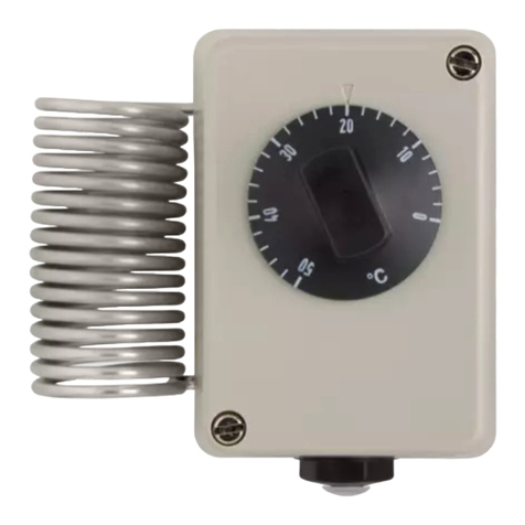
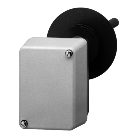
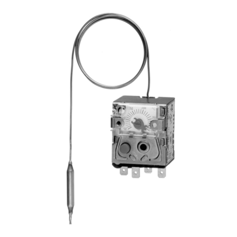
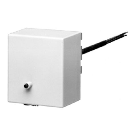
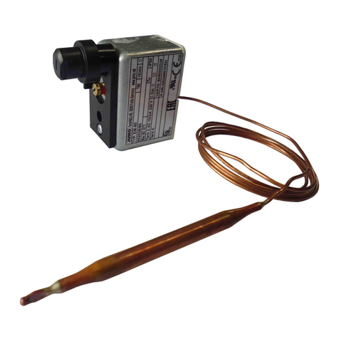
JUMO ATH.-SE Series User manual

60303100T90Z002K000
V5.01/EN/00073788/2021-05-25
Surface-mounting thermostats ATH.-SE-...
to monitor seagoing vessel equipment
Operating Manual

Contents
Contents
1 Safety information. . . . . . . . . . . . . . . . . . . . . . . . . . . . . . . . . . . . . . . . . . . . 5
1.1 Warning symbols. . . . . . . . . . . . . . . . . . . . . . . . . . . . . . . . . . . . . . . . . . . . . . . . . . . . . . . . . .5
1.2 Note symbols . . . . . . . . . . . . . . . . . . . . . . . . . . . . . . . . . . . . . . . . . . . . . . . . . . . . . . . . . . . .5
2 Introduction . . . . . . . . . . . . . . . . . . . . . . . . . . . . . . . . . . . . . . . . . . . . . . . . . 6
2.1 Brief description . . . . . . . . . . . . . . . . . . . . . . . . . . . . . . . . . . . . . . . . . . . . . . . . . . . . . . . . . .6
2.2 Intended use . . . . . . . . . . . . . . . . . . . . . . . . . . . . . . . . . . . . . . . . . . . . . . . . . . . . . . . . . . . . .7
2.3 Identification marking . . . . . . . . . . . . . . . . . . . . . . . . . . . . . . . . . . . . . . . . . . . . . . . . . . . . . .7
3 Identifying the device version . . . . . . . . . . . . . . . . . . . . . . . . . . . . . . . . . . 8
3.1 Nameplate. . . . . . . . . . . . . . . . . . . . . . . . . . . . . . . . . . . . . . . . . . . . . . . . . . . . . . . . . . . . . . .8
3.2 Order details . . . . . . . . . . . . . . . . . . . . . . . . . . . . . . . . . . . . . . . . . . . . . . . . . . . . . . . . . . . . .8
3.3 Scope of delivery . . . . . . . . . . . . . . . . . . . . . . . . . . . . . . . . . . . . . . . . . . . . . . . . . . . . . . . . .10
4 Mounting . . . . . . . . . . . . . . . . . . . . . . . . . . . . . . . . . . . . . . . . . . . . . . . . . . . 11
4.1 Dimensions . . . . . . . . . . . . . . . . . . . . . . . . . . . . . . . . . . . . . . . . . . . . . . . . . . . . . . . . . . . . . .11
4.2 Opening the housing. . . . . . . . . . . . . . . . . . . . . . . . . . . . . . . . . . . . . . . . . . . . . . . . . . . . . . .12
4.3 Fixing the device. . . . . . . . . . . . . . . . . . . . . . . . . . . . . . . . . . . . . . . . . . . . . . . . . . . . . . . . . .13
4.3.1 Code "s" (rigid shaft) . . . . . . . . . . . . . . . . . . . . . . . . . . . . . . . . . . . . . . . . . . . . . . . . . . . . . . .13
4.3.2 Code "f" (with capillary). . . . . . . . . . . . . . . . . . . . . . . . . . . . . . . . . . . . . . . . . . . . . . . . . . . . .13
4.4 Capillary, temperature probe and thermowell . . . . . . . . . . . . . . . . . . . . . . . . . . . . . . . . . . . .13
4.4.1 General information . . . . . . . . . . . . . . . . . . . . . . . . . . . . . . . . . . . . . . . . . . . . . . . . . . . . . . .13
4.4.2 Approved process connections. . . . . . . . . . . . . . . . . . . . . . . . . . . . . . . . . . . . . . . . . . . . . . .13
4.5 Permissible pressure at the thermowell . . . . . . . . . . . . . . . . . . . . . . . . . . . . . . . . . . . . . . . .14
4.5.1 Thermowells 20 and 30. . . . . . . . . . . . . . . . . . . . . . . . . . . . . . . . . . . . . . . . . . . . . . . . . . . . .14
4.6 Probe installation . . . . . . . . . . . . . . . . . . . . . . . . . . . . . . . . . . . . . . . . . . . . . . . . . . . . . . . . .15
5 Installation . . . . . . . . . . . . . . . . . . . . . . . . . . . . . . . . . . . . . . . . . . . . . . . . . . 16
5.1 Installation notes. . . . . . . . . . . . . . . . . . . . . . . . . . . . . . . . . . . . . . . . . . . . . . . . . . . . . . . . . .16
5.2 Connection diagram . . . . . . . . . . . . . . . . . . . . . . . . . . . . . . . . . . . . . . . . . . . . . . . . . . . . . . .17
5.2.1 Opening the housing. . . . . . . . . . . . . . . . . . . . . . . . . . . . . . . . . . . . . . . . . . . . . . . . . . . . . . .17
5.2.2 Close the housing . . . . . . . . . . . . . . . . . . . . . . . . . . . . . . . . . . . . . . . . . . . . . . . . . . . . . . . . .18
6 Startup . . . . . . . . . . . . . . . . . . . . . . . . . . . . . . . . . . . . . . . . . . . . . . . . . . . . . 20
6.1 Limit value setting . . . . . . . . . . . . . . . . . . . . . . . . . . . . . . . . . . . . . . . . . . . . . . . . . . . . . . . . .20
6.2 Unlocking the safety temperature limiter (STB) . . . . . . . . . . . . . . . . . . . . . . . . . . . . . . . . . .21
7 Technical data . . . . . . . . . . . . . . . . . . . . . . . . . . . . . . . . . . . . . . . . . . . . . . . 22
7.1 Control ranges and temperature probes . . . . . . . . . . . . . . . . . . . . . . . . . . . . . . . . . . . . . . . .22
7.2 Capillary and temperature probe . . . . . . . . . . . . . . . . . . . . . . . . . . . . . . . . . . . . . . . . . . . . .22
Contents
7.3 Electrical data . . . . . . . . . . . . . . . . . . . . . . . . . . . . . . . . . . . . . . . . . . . . . . . . . . . . . . . . . . . .23
7.4 Mechanical features . . . . . . . . . . . . . . . . . . . . . . . . . . . . . . . . . . . . . . . . . . . . . . . . . . . . . . .23
7.5 Environmental influences . . . . . . . . . . . . . . . . . . . . . . . . . . . . . . . . . . . . . . . . . . . . . . . . . . .24
7.6 Process connection. . . . . . . . . . . . . . . . . . . . . . . . . . . . . . . . . . . . . . . . . . . . . . . . . . . . . . . .25
7.7 Approvals and approval marks . . . . . . . . . . . . . . . . . . . . . . . . . . . . . . . . . . . . . . . . . . . . . . .26
8 Maintenance, cleaning and returns . . . . . . . . . . . . . . . . . . . . . . . . . . . . . . 27
8.1 Maintenance . . . . . . . . . . . . . . . . . . . . . . . . . . . . . . . . . . . . . . . . . . . . . . . . . . . . . . . . . . . . .27
8.2 Cleaning . . . . . . . . . . . . . . . . . . . . . . . . . . . . . . . . . . . . . . . . . . . . . . . . . . . . . . . . . . . . . . . .27
8.3 Returns . . . . . . . . . . . . . . . . . . . . . . . . . . . . . . . . . . . . . . . . . . . . . . . . . . . . . . . . . . . . . . . . .27
9 China RoHS . . . . . . . . . . . . . . . . . . . . . . . . . . . . . . . . . . . . . . . . . . . . . . . . . 28

5
1 Safety information
1 Safety informat ion
1.1 Warning symbols
WARNING!
This symbol in connection with the signal word indicates that personal injury may occur if the respective
precautionary measures are not carried out.
CAUTION!
This symbol in connection with the signal word indicates that material damage or data loss will occur
if the respective precautionary measures are not taken.
1.2 Note symbols
NOTE!
This symbol refers to important information about the product, its handling, or additional benefits.
READ THE DOCUMENTATION!
This symbol, which is attached to the device, indicates that the associated documentation for the de-
vice must be observed. This is necessary to identify the nature of the potential hazard, and to take
measures to prevent it.
DISPOSAL!
At the end of its service life, the device and any batteries present do not belong in the trash! Please en-
sure that they are disposed of properly and in an environmentally friendly manner.

6
2 Introduction
2 Introduction
2.1 Brief description
Thermostats are used to control and monitor thermal processes. The devices of the ATH.-SE type series
are available as temperature monitors TW, safety temperature monitors STW (STB) and safety tempera-
ture limiters STB. In the event of a malfunction, the STB switches the monitored machine line to an op-
erational safe status.
Surface-mounting thermostats operate according to the fluid expansion principle, a microswitch is used
as an electrical switching element.
Switching function
Temperature monitor TW and safety temperature monitor STW
If the temperature on the temperature probe exceeds the limit value, the electrical circuit is opened by a
microswitch. When the limit value falls below the set limit value (by the switching differential), the switch
is returned to its initial position.
Restart lock at safety temperature limiter STB
If the temperature at the temperature sensor exceeds the set limit value, the electrical circuit is opened
and mechanically locked. After falling below the limit value by approx. 10 % of the temperature range,
the switch can be unlocked manually.
Use of the safety temperature monitor STW as safety temperature limiter STB
In this case, the circuit following the thermostat must comply with DIN EN 14597 and VDE 0116.
Self-monitoring for safety temperature limiter STB and safety temperature monitor STW (STB)
If the measuring system is destroyed (i.e. if the expansion fluid escapes) the pressure in the membrane
of the STB and STW (STB) drops and permanently opens the electrical circuit. Unlocking is then no lon-
ger possible. When the STB sensor cools down to the negative temperature range, the circuit opens, but
must be manually unlocked by the reclosing button when the temperature rises. The STW (STB) auto-
matically restarts.

7
2 Introduction
2.2 Intended use
The device is approved for monitoring installations on steel-hulled seagoing ships (e.g. steam and boiler
plant, indirect heating systems) as:
• Temperature monitor (TW)
• Safety temperature monitor STW (STB)
• Safety temperature limiter (STB)
The version complies with DIN EN 14597 and is approved as per the guidelines of the Classification So-
cieties:
• DNV GL
• Bureau Veritas
• Pressure Equipment Directive 2014/68EU (ATH.-SE-20[STW] and ATH.-SE-70[STB] only)
CAUTION!
Failure of the device
Cutting through or kinking the capillary will lead to permanent failure of the device!
NOTE!
If the measuring system breaks, the filling liquid can escape. So far, there is no restrictive health authority
statement on a health hazard in the case of short-term exposure and low concentration, e.g. in the case
of a measuring system breakage.
Note
Physical and toxic features of the expansion means, which could occur in the event of a measuring sys-
tem break.
2.3 Identification marking
NOTE!
The device is approved as per DIN EN 60730-2-9.
Control range with
scale limit value
Hazardous
reactions
Fire and explosion hazard Hazardous
to waters
Information about toxicology
Ignition
temperature
Explosion
limit
Irritant Dangerous
to health
Toxic
<200°C No 355°C 0.6to8V% Yes Yes aNo
≥200°C
≤300°C
No 490 °C - Yes Yes aNo
aThere is currently no statement by the health authority concerning hazards to health in the event of short-term ex-
posure and low concentration, e.g. measuring system break.

8
3 Identifying the device version
3 Identi fying t he device version
3.1 Nameplate
Exemplary marking on the device housing:
3.2 Order details
(1) Order code
(2) Control range/contact rating
(3) Approval mark
(1) Basic type
603031 Surface-mounting thermostat ATH.-SE
(2) Basic type extension
02 ATH.-SE-2 Temperature monitor TW
20 ATH.-SE-20 Safety temperature monitor (STW [STB])
70 ATH.-SE-70 Safety temperature limiter (STB)
(3) Design
1ATHs-SE-.. rigid shaft
2ATHf-SE-.. capillary
(4) Control range (TW)
025 0 to 100 °C
041 20 to 90 °C
042 20 to 120 °C
043 20 to 150 °C
052 30 to 110 °C
062 50 to 200 °C
063 50 to 250 °C
064 50 to 300 °C
067 60 to 140 °C
(5) Hysteresis
00 None
15 1.5 %
30 3 %
60 6 %
(6) Capillary length
0 None
1000 1000 mm
2000 2000 mm

9
3 Identifying the device version
(7) Capillary material
00 None
20 CrNi (stainless steel)
40 Cu (copper)
(8) Process connection
10 Plain cylindrical probe
20 Screw-in thermowell
30 Screw-in thermowell with intermediate piece
(9) Process connection thread
00 None
13 G 1/2
(10) Process connection material
00 None
20 CrNi (stainless steel)
40 CuZn (copper)
(11) Insertion length
000 Without thermowell
100 100 mm
120 120 mm
150 150 mm
200 200 mm
(12) Immersion tube diameter
00 Without thermowell
08 8 mm
10 10 mm
(13) Probe diameter
66mm
88mm
(14) Extra codes
000 None
574 Microswith with N/C contact, restart lock and additional signal contact (only for STB)
(1) (2) (3) (4) (5) (6) (7) (8)
Order code /-------
Order example 603031 / 20 - 1 - 025 - 15 - 0 - 00 - 20 -
(9) (10) (11) (12) (13) (14)
- - - - / , ...a
13 - 46 - 150 - 8 - 6 / 000
aList extra codes in sequence, separated by commas.

3 Identifying the device version
10
3.3 Scope of delivery
Device in the version ordered
Operating manual

11
4 Mounting
4 Mounting
4.1 Dimensions
ATHs-SE-2 (20)
with screw-in thermowell „20“, up to 150 °C
K M24x1,5
M 20x1,5
DIN 89280-Z14
27
70
66
G1/2
33
14
Ø 26
S = max. 200 (150)
67
94
ATHs-SE-70
with screw-in thermowell and intermediate piece „30“, 150 to 300 °C
K M24x1,5
M 20x1,5
DIN 89280-Z14
70
66
G 1/2
Ø 26
S = max. 200 (150)
Ø 90
~85
14
27
Ø

4 Mounting
12
4.2 Opening the housing
1. Unscrew the two lead-sealable cheese-head screws (5).
2. Remove the upper part ov the housing (1).
CAUTION!
Ensure that the gasket is seated correctly when reassembling!
ATHs-SE-70
with screw-in thermowell „20“, up to 300 °C
K M24x1,5
M 20x1,5
DIN 89280-Z14
70
12
66
G1/2 14
G1/2
Ø 26
S = max. 200 (150)
33
67
94
24
27
Ø

13
4 Mounting
4.3 Fixing the device
Operating position: Any, for open-air mounting on request
4.3.1 Code "s" (rigid shaft)
The housing journal is secured in the enlarged open end of the thermowell by two fixing screws.
4.3.2 Code "f" (with capillary)
Fixing is by G 1/2 screw connection on the housing spigot.
4.4 Capillary, temperature probe and thermowell
4.4.1 General information
CAUTION!
Failure of the device
Cutting through or kinking the capillary will lead to permanent failure of the device!
Minimum permissible bending radius of the capillary is 5 mm.
The temperature probe must be fitted in a JUMO thermowell, otherwise the approval of the device ex-
pires.
NOTE!
The temperatur probe must be completely submerged in the medium.
In order to ensure the general accuracy of response, the devices must only be used with the thermowells
supplied from the factory (diameter D = 8 or 10 mm).
Only probes with a diameter D = 8 mm may be fitted in thermowells with a diameter D = 10 mm.
When the operating medium is air, connection type „10“ (without thermowell) must be selected.
4.4.2 Approved process connections
Temperature probe
Process connection 10: Plain cylindrical probe (only with ATHf-SE)
Thermowells
Process connection 20: Screw-in thermowell,
process connection 30: Screw-in thermowell with intermediate piece
NOTE!
For detailed information, refer to data sheet 606710.

4 Mounting
14
4.5 Permissible pressure at the thermowell
4.5.1 Thermowells 20 and 30
CAUTION!
The following values refer to the maximum pressure of the probe mounting concerned. The max-
imum pressure which can be sealed depends on the mounting conditions and may possibly be
lower.
Thermowell „20“ made of stainless steel
Thermowell „20“ made of brass
NOTE!
The process connection plain cylindrical probe must only be used in pressureless medium.
CAUTION!
Due to the general accuracy of response, the device must only be used with the factory-supplied
thermowell.
Material
Tube and screw connection CrNi
Temperature in °C Tube diameter
8×0.75mm
Tube diameter
10 × 0.75 mm
Max. permissible pressure in bar
100 92 74
150 88 71
200 83 67
300 72 58
Permitted flow velocities Upon request
Material
Tube and screw connection CuZn, nickel plated
Temperature in °C Tube diameter
8×0.75mm
Tube diameter
10 × 0.75 mm
Max. permissible pressure in bar
100 50 40
150 48 39
Permitted flow velocities Upon request

15
4 Mounting
4.6 Probe installation
NOTE!
Submerge the thermwell and the temperatur probe into the medium. Ensure that the temperature probe
is completely submerged in the medium because otherwise, greater switching point deviations will occur.
For thermostats with capillary (code „f“), and a screw-in thermowell (process connectin 20) the tempera-
ture probe is fixed in the thermowell with the clamping piece.
(1) Clamping piece
(2) Temperature probe

16
5 Installation
5
Installation
NOTE!
If you determine an external defect – also a mechanical way – the differential pressure transmitter has
to be sent for repair to the manufacturer.
5.1 Installation notes
CAUTION!
The electrical connection must only be made by qualified personnel.
The choice of cable, the installation and the electrical connection must conform to the requirements of
VDE 0100 „Regulations for the installation of power circuits with nominal voltages below 1000 V“, or the
appropriate local regulations..
If contact with live parts is possible while working on the unit, it must be completely disconnected from
the supply.
Earth the instrument at the PE terminal to the protective conductor. This cable must have a cross-section
that is at least as large as the supply cables. Earth cables must be run in a star configuration to a com-
mon earth point which is connected to the protective earth of the supply. Do not loop earth cables, i.e.
do not run them from one instrument to another.
Apart from faulty installation, incorrect settings on the thermostat can affect the proper functioning of the
following process or lead to damage. Setting up must therefore be restricted to qualified personnel.
Please observe the appropriate safety regulations in this respect.

17
5 Installation
5.2 Connection diagram
5.2.1 Opening the housing
1. Open the housing, chapter 4.2 "Opening the housing", Page 12.
2. Pass the connection cable (cable diameter 10 to 16.5 mm) through the screw connection (C);
fitting type „X“ (no special tools), screw connection up to 2.5 mm2 conductor cross-section.
3. Establish the connection to the terminals (A) in accordance with the appropriate connectin diagram.
4. Connect the protective conductor to terminal PE (B).
NOTE!
Tightening torque of the clamping screws/protective earth conductor clamp (PE) = 0.45 to 0.68 Nm
Wiring diagrams
TW/STW (STB) STB as N/C contact with signal contact STB with N/C contact

5 Installation
18
5.2.2 Close the housing
1. Make sure that the plastic gasket in the lower part of the housing (B) is checked for correct fit.
NOTE!
On the thermostate with code -70, the external reset button (C) must be located precisely on top the
internal reset button (D) on the microswitch. Only in this way can the restart button be actuated from the
outside (C).
2. Place the upper part of the housing (A) onto the lower part (B).
3. Tighten the lead-sealable cheese-head screws (E).

19
5 Installation
Cable relief
1. Turn the screw connection (A) clockwise until the cable inlet is sealed.
The cable entry is secured against being pulled out.
2. The cable has to be protected against vibration overload by leaving sufficient extra cable length (B).
3. Close the housing.
Other manuals for ATH.-SE Series
1
This manual suits for next models
3
Table of contents
Other JUMO Thermostat manuals

JUMO
JUMO heatTHERM-AT User manual

JUMO
JUMO EM Series User manual

JUMO
JUMO B 70.1050.0 User manual

JUMO
JUMO AMRc-1 User manual

JUMO
JUMO AMDR-1 User manual

JUMO
JUMO EM Series User manual

JUMO
JUMO EMf-80 Series User manual

JUMO
JUMO ATHs-SW Series User manual

JUMO
JUMO WTHc Series User manual

JUMO
JUMO ATH SW Series User manual
Popular Thermostat manuals by other brands

ritetemp
ritetemp 8010 install guide

Texas Instruments
Texas Instruments LM5013-Q1EVM user guide

Honeywell
Honeywell VisionPRO Series user guide

White Rodgers
White Rodgers 1F58 installation instructions

Aube Technologies
Aube Technologies TH110A-SP-P installation guide

Charmeg
Charmeg T10 installer and user manual