Jun-Air 6-4 User manual

OPERATING MANUAL
BETRIEBSANWEISUNG
MODE D’EMPLOI
MODO DE EMPLEO
GEBRUIKAANWIJZING
BETJENINGSFORSKRIFT
Compressor
Model 6-4 / 6-10 / 6-15 / 6-25 &
12-25 / 12-50

Table of contents
3
TABLE OF CONTENTS
OPERATING MANUAL ........................................................................................ 4
WARNING ........................................................................................................................................ 4
GUARANTEE ................................................................................................................................... 4
HOW TO OPERATE THE JUN-AIR COMPRESSOR ................................................................... 5
TECHNICAL DETAILS ................................................................................................................... 6
PREVENTIVE COMPRESSOR MAINTENANCE ........................................................................ 7
FAULT FINDING AND REPAIR ..................................................................................................... 9
SPARE PARTS ................................................................................................................................10
BETRIEBSANWEISUNG ................................................................................... 11
ACHTUNG ...................................................................................................................................... 11
GARANTIE ..................................................................................................................................... 11
SO WIRD DER JUN-AIR KOMPRESSOR BEDIENT ................................................................ 12
TECHNISCHE DATEN .................................................................................................................. 13
VORBEUGENDE KOMPRESSORWARTUNG ........................................................................... 14
FEHLERSUCHE UND REPARATUR ........................................................................................... 16
ERSATZTEILE................................................................................................................................ 17
MODE D’EMPLOI............................................................................................... 18
AVERTISSEMENT......................................................................................................................... 18
GARANTIE ..................................................................................................................................... 18
COMMENT UTILISER LE COMPRESSEUR JUN-AIR............................................................. 19
CARACTERISTIQUES TECHNIQUES........................................................................................ 20
PRECAUTIONS A PRENDRE POUR UN BON ENTRETIEN .................................................. 21
RECHERCHE DE PANNES ET REPARATIONS ........................................................................ 23
PIECES DETACHEES.................................................................................................................... 24
MODO DE EMPLEO .......................................................................................... 25
ADVERTENCIAS PRELIMINARES ............................................................................................ 25
GARANTIA..................................................................................................................................... 25
MODO DE EMPLEO Y MANTENIMIENTO DEL JUN-AIR..................................................... 26
DETALLES TÉCNICOS ................................................................................................................. 27
MANTENIMIENTO PREVENTIVO DEL COMPRESOR .......................................................... 28
DIAGNOSTICO DE FALLAS Y REPARACIONES ..................................................................... 30
PIEZAS DE RECAMBIO ............................................................................................................... 31
GEBRUIKSAANWIJZING .................................................................................. 32
LET OP ............................................................................................................................................ 32
GARANTIE ..................................................................................................................................... 32
BEDIENING VAN DE JUN-AIR COMPRESSOR ....................................................................... 33
TECHNISCHE GEGEVENS .......................................................................................................... 34
PREVENTIEF ONDERHOUD VAN DE COMPRESSOR ........................................................... 35
OPSPOREN EN VERHELPEN VAN STORINGEN..................................................................... 37
ONDERDELENLIJST .................................................................................................................... 38
BETJENINGSFORSKRIFT ................................................................................ 39
ADVARSEL..................................................................................................................................... 39
GARANTI........................................................................................................................................ 39
SÅLEDES BETJENES JUN-AIR KOMPRESSOREN ................................................................. 40
TEKNISKE DATA........................................................................................................................... 41
FOREBYGGENDE KOMPRESSORVEDLIGEHOLDELSE ....................................................... 42
FEJLFINDING OG REPARATION ................................................................................................ 44
RESERVEDELSLISTE ................................................................................................................... 45
DRAWINGS ........................................................................................................ 46
MOTOR SPARE PARTS MODEL 6 .............................................................................................. 46
SPARE PARTS MODEL 6-4/6-10/6-15/6-25................................................................................ 47
SPARE PARTS MODEL 12-25/12-50 ........................................................................................... 48
ACCESSORIES .............................................................................................................................. 49

Operating manual
4
OPERATING MANUAL
WARNING
lUnless directions are followed and original spare parts used, physical injury or
property damage may result.
lProtect compressor against rain, moisture, frost, and dust.
lCompressor is only suitable for installations with the nominal voltage stated on
the motor plate.
lDo not in any way block or prevent the normal functioning of the safety valve
onthe receiver.
lOnly connect pneumatic equipment suitable for the max. pressure indicated.
lDo not operate compressor at ambient temperatures exceeding 35°C/95°F or
falling below 0°C/32°F.
lDo not touch compressor motor during operation as there is a risk of burn due
to high temperatures.
lDo not direct air flow at head or body.
lWhen a flammable liquid is sprayed, there may be danger of fire or explosion,
especially in closed rooms.
lAlways keep the compressor out of reach of children.
GUARANTEE
Provided that the operational instructions have been carried out, your JUN-AIR
compressor is guaranteed against faulty material or workmanship for 2 years.
The air receiver is guaranteed for 5 years.
The guarantee does not cover damage caused by violence, misuse, incorrect
repairs or use of wrong oil and unoriginal spare parts.
Costs of transportation of parts/equipment are not covered by the guarantee.
JUN-AIR’s Conditions for Sale and Delivery will generally apply.
JUN-AIR International A/S reserves the right to change technical specifications/
constructions.

Operating manual
5
(fig. 4)
(fig. 3)
(fig. 2)
(fig. 1)
HOWTO OPERATETHE JUN-AIR COMPRESSOR
Your JUN-AIR compressor is very easy to operate. Observe the following simple
instructions and you will get many years’ service from your compressor.
1. Visually inspect unit for shipping damage, contact your supplier immediately if
you think the unit may have been damaged.
2. Always keep the compressor in a vertical position during use and
transportation.
3. Place the compressor in a dustfree, dry and cool, yet frostfree, room. Do not
install in a closed cupboard, unless adequate openings for ventilation are
available (fig. 1). Ensure that the compressor stands firmly on the floor.
4. Replace the cap on the air intake tube with the intake filter (fig. 2).
5. Connect pneumatic equipment.
Important!
The compressor oil may be aggressive towards certain gasket
materials used in pneumatic equipment.We recommendTeflon,
Viton, etc.. Do not use polycarbonate filter bowls. Contact your
local JUN-AIR distributor if you need further information.
6. Plug the compressor into an outlet switch of nominal voltage and ensure that
fusing is adequate (see Technical Details).
7. Start the compressor using the 0/1 switch on the pressure switch (fig. 3). The
compressor will automatically switch off at the preset pressure. If the motor
does not start it may be due to pressure in the receiver, and the motor will then
start automatically when the pressure reduces to approx. 6 bar/87 psi.
8. Always keep the compressor in a vertical position as oil may run out of the
intake filter. During transportation, mount the cap on the inlet. Mechanical
noise from the compressor in connection with handling does not have any
functional importance.
Warning!
Never mount the transportation cap on oil-lubricated compressors
while there is still pressure in the compressor & pressure vessel,
as this may cause a pressure build up in the motor housing.
9. Adjustment of pressure (fig. 4):
A: Max. pressure adjustment (cut-out)
B: Differential adjustment (cut-in)
The cut-in pressure (normally 6 bar) is set by adjustment of differential screw
B. Turn clockwise to reduce cut-in pressure.
The cut-out pressure is set by even adjustment of the two screws A. (Cut-in
pressure + differential = cut-out pressure). Turn clockwise to increase cut-out
pressure.
The switch is normally factory set for operation at 6-8 bar (approx. 90-120
psi).

Operating manual
6
TECHNICAL DETAILS
The max. operation of the compressor is 50% of the operation time, and
the max. operation time is 15 min. at 8 bar/120 psi in each cycle.
Consequently, 15 min. standstill is required before the next start.
0991302a
Model 6
0991303a
Model 12
Model
Voltage Volt±10%/Hz 120/60 120/60 120/60
HP 0 54 0 54 0 54
kW 0 40 0 40 0 40
l/min 60 60 60
CFM 2 12 2 12 2 12
bar
psi
Power consumption
at 8 bar liter
US gall
kg
lbs
l 420 - 16 4/8 350 - 13 6/8 380 - 15
w 300 - 11 6/8 350 - 13 6/8 380 - 15
h310 - 12 2/8 450 - 17 6/8 480 - 18 7/8
Noise level dB(A)/1m
Pumping time
0-8 bar (0-120 psi)
2)
Model
Voltage Volt±10%/Hz 120/60 120/60 120/60
HP 0 54 1 08 1 08
kW 0 40 0 80 0 80
l/min 60 120 120
CFM 2 12 4 24 4 24
bar
psi
Power consumption
at 8 bar liter
US gall
kg
lbs
l 380 - 15 400 - 15 6/8 760 - 29 7/8
w 380 - 15 410 - 16 1/8 450 - 17 6/8
h550 - 21 5/8 590 - 23 2/8 620 - 24 3/8
Noise level dB(A)/1m
Pumping time
0-8 bar (0-120 psi) 2)
6 2 2 9 6 2
0 46
45
165
230/50
0 46
0 34
50
57
1 77
45 45
50
1 77 50
1 77
46 25
55
2 9
6-15
8
120
Weight
Tank size
88
120 120
0 46
Dimensions mm - inch
amp
Motor
Displacement
Max pressure 1)
2) Plus/minus 10% Average at 20°C/68°F motor start temperature Technical modifications reserved
40 9550 195115
sec.
1) Higher pressure available upon request
6-4 6-10
4
2 9
10
230/50 230/50
0 340 34 0 46
6-25 12-25 12-50
6 2
1 1 2 6
21
15
4 0
26
230/50 230/50 230/50
Motor 0 92 0 92
0 68 0 680 34
Displacement 100 100
3 54 3 54
50
1 77
Max pressure 1) 888
120 120 120
amp 2 9 6 2 5 8 12 4 5 8 12 4
Tank size 25 25 50
6 6 6 6 13 2
Weight 29 45 57
64 99 126
Dimensions mm - inch
45 48 48
2) Plus/minus 10% Average at 20°C/68°F motor start temperature Technical modifications reserved
130 340 285
1) Higher pressure available upon request
sec. 325 270 155

Operating manual
7
PREVENTIVE COMPRESSOR MAINTENANCE
Weekly Monthly Annually
Check oil level. During standstill the
correct level is between the maximum
and the minimum indications.
Use only genuine SJ-27 synthetic oil.
Do not overfill (fig. 1).
●
Drain condensate from air receiver (at a
pressure of max. 2 bar/30 psi) (fig. 2). If
fitted with auto drain, this will take place
automatically, however, drain bottle has
to be emptied.
●
If compressor is fitted with outlet filter,
check and empty for water by pressing
the black button in the bottom. If fitted
with auto drain, this will take place
automatically.
●
Check compressor, air tubes and
equipment for leaks, and check the
pumping time. ●
Inspect and replace intake filter, if
necessary. ●
Clean the compressor with a soft, damp
cloth. Dust and dirt prevent cooling. ●
Check the O-ring in the non-return valve
and replace if necessary (fig. 3).
Note! Empty receiver of air before
dismounting.
●
Check filter and filter elements for
optimum efficiency. ●
Test the safety valve by gently pulling the
ring with pressure in the receiver (fig. 4). ●
(fig. 1)
(fig. 2)
(fig. 4)
(fig. 3)

Operating manual
8
Oil change
In connection with repair of model 6 motors, e.g. change of valve plate or other
internal motor parts or in case the compressor is installed in a very dusty
environment, oil change may be necessary. Proceed as follows:
1. Remove the ribbed cover by loosening the 4 screws (fig. 1).
2. Tilt the motor towards side with outlet and at the same time hold the internal
motor parts in place with hand. Pour all oil out of housing (fig. 1). In case of
dirt particles at the bottom of the motor housing, clean with a rag.
Note!
Waste oil is to be handled according to the environmental rules in
force in the country.
3. Tilt the motor back and fill with SJ-27 oil (approx. 0.75l) (fig. 1).
4. Clean the edge of casing and cover. Check the O-ring of the ribbed cover.
5. Replace the ribbed cover and check during operation that the O-ring is placed
correctly to ensure a 100% tight closing between housing and cover.
Important!
Always use SJ-27 oil as other types of oil may cause serious
mechanical damage to the compressor. Consequently, the
warranty only applies if SJ-27 oil is used.
Check the pumping time
The pumping time indicates the condition of the compressor provided that there
are no leaks in the system where the compressed air may leak. Test the compressor
as follows:
1. Empty the air receiver of compressed air (the pressure gauge shows 0 bar).
2. Close the outlet on the air receiver and check that the drain cock is closed.
3. Start the compressor and note how long it takes until it switches off.
Make sure that the pressure in the air receiver is 8 bar/120 psi as deviations
may indicate the wrong results (see technical details).
Important!
Always test the compressor when cold as the time indicated refers
to the pumping time of a cold compressor.The pumping time of a
warm compressor is much longer and consequently, the result
would be misleading.
(fig. 1)

Operating manual
9
FAULT FINDING AND REPAIR
Important!
Switch off and isolate from electrical supply before removing any
parts from the compressor.
Empty air receiver of air before dismantling any parts of
compressor unit’s pressure system.
1. Compressor does not start:
a) No power from mains. Check fuses and plug.
b) Breakage or loose joints in electrical connections.
c) The starting relay is defective. Contact your JUN-AIR distributor.
d) The pressure switch is defective and does not switch on the compressor.
e) The thermal protection has switched off the compressor due to overheating.
When cooled the compressor will automatically turn on at a suitable operation
temperature. Go through the points in section 4.
f) Pressure in the air receiver is too high for activation of the pressure switch.
The pressure switch makes circuit only when pressure has dropped to preset
start pressure. Empty the receiver.
g) The compressor has not been unloaded and there is back pressure on the
piston. Dismount and check unloader valve (fig. 1). The back pressure may be
due to a leaking non-return valve causing the compressed air in the receiver to
leak back into the compressor motor. Dismount the non-return valve and clean
or change O-ring (fig. 2).
h) Capacitor defective.
2. Compressor operates, but pressure does not increase in tank (or
increases too slowly):
a) The cap on the intake tube has not been removed and replaced by the intake
filter (fig. 3).
b) Intake filter is clogged. Replace.
c) Leaks in fittings, tubes or pneumatic equipment. Check with soapy water or by
letting unit stay overnight with disconnected mains. Pressure drop is not to
exceed 1 bar.
d) Clogged non-return valve or pressure pipe. Clean or replace the parts
(fig. 2).
e) Air leaks from the unloader valve when the compressor is operating. Check or
replace the unloader valve (fig. 1).
f) Defective valve plate. Contact your JUN-AIR distributor.
3. Loud noise from compressor:
a) Most likely broken suspension spring(s). Replace the spring and ensure that
motor position is horizontal.
b) The internal pressure pipe touches the rib cover or the cylinder block.
Dismount the rib cover and bend the pressure pipe away.
4. Compressor gets very hot and/or uses a lot of oil:
a) Incorrect oil level. The level must appear in the oil level glass (fig. 4).
b) Wrong oil has been filled in the compressor. Use only SJ-27 synthetic lubricant
which has the correct viscosity.
c) Leaks. See point 2c.
d) Clogged intake filter. See point 2b.
e) Too high ambient temperature. Do not install the compressor in a cabinet
unless adequately ventilated (fig. 5).
f) The compressor is overloaded (i.e. it is operating more than 50% of the
operation time). Contact your JUN-AIR distributor.
5. Compressor starts when no air is being used:
a) Leaks. See point 2c.
6. Compressor starts and stops more frequently than usual:
a) Condensate in the air receiver. Empty the receiver by means of the drain cock
(fig. 6).
b) Leaks. See point 2c.
(fig. 1)
(fig. 2)
(fig. 4)
(fig. 3)
(fig. 5)
(fig. 6)

Operating manual
10
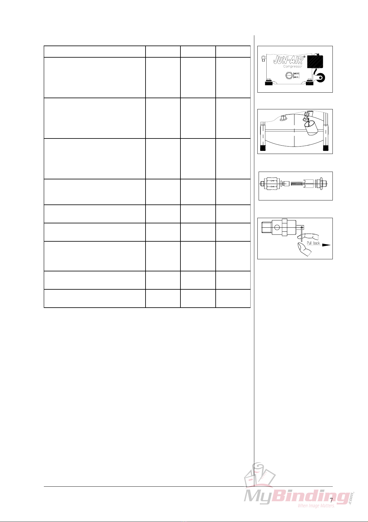
(Please refer to the back for drawings) SPARE PARTS
3010000 Tank 4l, no IP 5419000 Drain cock 1/4" 10l
3010500 Tank 4l, 1 IP 5419100 Drain cock 3/8" 10l
3110000 Tank 10l EC, 1 IP 5419500 Drain cock 1/4" 15l
3115000 Tank 10l, no IP 5419600 Drain cock 3/8" 15l
3210000 Tank 15l CE, 1 IP 5420000 Drain cock 1/4" 25l
3214000 Tank 15l, no IP 5420100 Drain cock 3/8" 25l
3410000 Tank 25l CE, 1 IP 5421000 Drain cock 1/4" 40/50 l
3410500 Tank 25l, no IP 5421100 Drain cock 3/8" 40/50l
3610000 Tank 50l CE, 2 IP 5424000 Outlet cock 1/4"
4070500 Act. carbon filter DH AC-0003G 5425000 Distributor f/non-return valve
4071000 Filter 5u man. F07-220-M1MG 5425500 Safety valve TšV 10 bar
4071020 Regulator R07-280-RNMG 5426500 Safety valve TšV 16 bar
4071030 Filter reg 5u man B07-280-M1MG 5427000 Connecting piece
4071055 Filter 0.01u man F39-220-M0MG 5429000 Adaptor 5-way compl.
4071080 Lubricator L07-220-MPMG 5429100 Adaptor 4-way compl.
4110000 Rapid coupler 1/4" 5429500 Adaptor 2-way compl.
4120000 Nipple 1/4" 5470300 Kit repl. valve plate M6
4130000 Hose tail nipple 1/4" 5940000 Plastic insulation
4210000 Trolley f/6-10/15/25 5950000 Plastic slide
4211000 Trolley f/6-4/3-1.5 5960000 Cable relief
4310000 Blow gun black 5990000 Rubber base f/M12
4311000 Blow gun black 6235000 Gasket f/oil filling
4380000 Ball inflator 6241800 O-ring f/1" plug - 32x5 mm
4381000 Bicycle inflator 6244000 O-ring f/rib cover
4382000 Car tyre inflator 6246000 O-ring f/2" plug
4383000 Hose clamp 8-12 mm 6250000 Socket 25 mm black
4410000 PVC air hose 1/4" 6252000 Socket f/handle f/3-1.5/6-4
4430000 Recoil air hose 1/4" 7.5 m 6253000 Base f/handle ø25x25 M8x8
4510000 Motor parts internal 230V M6 6271000 Rubber grommet f/motor M6
4511000 Motor parts internal 120V M6 6290200 Grip for handle
4520000 Overload protector M6 230V 6290300 Grip for handle
4521000 Overload protector M6 120V 6311000 Bolt M8x25 FZB
4522500 Overload spring 6312000 Bolt M8x35 FZB
4523000 Starting relay 230V M6 6320000 Nut M8 FZB
4524000 Starting relay 120V M6 6320200 Counter nut M8 flat FZB
4525000 Starting relay 100V M6 6330000 Screw CHJ M4x5 FZB
4526500 Connecting board compl. M3/M6 6341900 Bolt M6x16
4526600 Cover f/connecting board M3/M6 6350000 Washer ø23x11.5x1.5 mm FZB
4527000 Fastening spring M3/M6 6351000 Clamp
4528000 Bolt f/top bearing M6 6372700 Lock nut M8 FZB
4529000 Top bearing M6 6413000 Flex pipe 1/8" 13(15) cm
4545000 Cover M6 6417000 Flex pipe 1/8" 17 (19)cm
4546000 Gasket f/cover M6 6420000 Flex pipe 1/8" 20 (22) cm
4547000 Pressure pipe M6 6433000 Flex pipe 1/8" 33 (35)cm
4549000 Bolt f/pressure pipe M6 6439000 Flex pipe 1/8" 39 (41)cm
4550000 Copper washer M6 6950000 Wheel ø200x50mm
4551000 Suspension spring M6 6960000 Locking ring A20 f/M12
4555000 Cylinder head M6 6961000 Distance tube 23.3 mm
4556000 Bolt f/cylinder head M6 6961200 Distance tube 27 mm
4561000 Casing bottom part M6 6973080 Unloader valve w/16.4mm needle
4571000 Rib cover M6 6975000 Silencer SE-M5
4750000 Control lamp 230V 7023000 Hose tail 1/4"
4750200 Control lamp 120V 7024000 Double nipple 1/4" L = 26 mm
5030000 Pressure switch MDR 2/11 7070500 Conn. pce f/non-ret.-valve M12
5033000 Press. switch MDR21/11 UL unl. 7070600 Conn. pce f/non-ret.-vlv M4000
5035000 Pressure switch MDR2/11 compl. 7071000 T-piece 1/8"
5110000 Gauge ø50 - 0-16bar 1/4" back 7071400 Cross connector Condor
5130000 Gauge ø40 - 0-16 bar 1/8" down 7156000 Extension piece f/cock
5210000 Capacitor start 70uF 7156100 Extension piece f/cock (84cm)
5230000 Capacitor start 160 uF UL 7164200 Cross connector f/3-1.5/6-4
5320000 Handle f/6-4 7164900 Plug 1" f/inspection plug
5330000 Handle f/6-10 7166700 Plug 2" f/inspection plug
5340000 Handle f/6-15 & 6-25 7180000 Elbow 1/4"
5350000 Hand lever f/M12 7190000 Elbow 1/8"
5410000 Oil level glass compl. 7525000 Hose tail f/coupling nut
5412000 Intake filter compl. 7566000 Bushing 1/4" x 1/4"
5414000 Oil inlet screw w/gasket 7567000 Bushing 1/4" x 3/8"
5414500 Non-return valve 7573000 Nut f/rib cover
5416000 Safety valve 10bar/145psi 7575000 Coupling nut 1/4"
5416200 Safety valve 16bar/232psi 8105000 Bracket f/M12-15/25 compl.
5418000 Drain cock 1/4" 4l

Betriebsanweisung
11
BETRIEBSANWEISUNG
ACHTUNG
lBei Nichtbeachtung der folgenden Anweisungen sowie Verwendung nicht
originaler JUN-AIR Ersatzteile können Verletzungen und Sachschaden
entstehen.
lKompressor vor Feuchtigkeit, Nässe, Frost und Staub schützen.
lDer Kompressor darf nur an Installationen angeschlossen werden, deren
Spannung und Frequenz mit den Angaben auf dem Typenschild des Motors
übereinstimmen.
lDie Funktionsfähigkeit des Sicherheitsventils darf nicht beeinträchtigt werden.
lAchten Sie darauf, daßder Luftbedarf der nachgeschalteten Anlage der
Kompressorleistung entspricht.
lDie Umgebungstemperatur des Kompressors darf maximal 35°C betragen, und
0°C nicht unterschreiten.
lDer Kompressormotor entwickelt eine hohe Betriebstemperatur. Um
Verletzungen zu vermeiden, darf der Kompressor deshalb während des
Betriebes nicht berührt werden.
lRichten Sie den Luftstrom niemals direkt auf den Körper.
lBeim Versprühen von brennbarer Flüssigkeit besteht Feuer- oder
Explosionsgefahr, besonders in geschlossenen Räumen.
lStellen Sie den Kompressor außerhalb der Reichweite von Kindern auf.
GARANTIE
Vorausgesetzt, daßdie Bedienungsvorschriften eingehalten werden, wird für alle
Material- und Fertigungsfehler 2 Jahre Garantie geleistet.
Auf den Behälter wird eine 5 Jahre Garantie geleistet.
Die Garantie gilt nicht für Schäden, die durch Gewalt, Mißbrauch, fehlerhafte
Reparaturen oder Verwendung von nicht originalen Öltypen und Ersatzteilen
entstehen.Transportkosten sind von der Garantie ausgeschlossen.
Für alle Abwicklungen sind die Geschäfts- und Lieferungsbedingungen der Firma
JUN-AIR International A/S maßgeblich.
Firma JUN-AIR International A/S behält sich das Recht vor, technische
Verbesserungen und Konstruktionsänderungen vorzunehmen.

Betriebsanweisungt
12
(Abb. 4)
(Abb. 2)
(Abb. 1)
(Abb. 3)
SOWIRD DER JUN-AIR KOMPRESSOR BEDIENT
Ihr JUN-AIR Kompressor ist sehr leicht zu bedienen. Beachten Sie nachfolgende
Anleitungen, und der Kompressor wird Ihnen viele Jahre gute Dienste leisten.
1. Überprüfen Sie, daßdas Gerät keine Transportschäden aufweist. Bitte
eventuelle Beschädigungen sofort beanstanden.
2. Sorgen Sie dafür, daßdas Gerät im Betrieb und beim Transport immer aufrecht
steht.
3. Achten Sie darauf, daßder Kompressor in einem staubfreien, trockenen und
frostfreien Raum aufgestellt wird. Stellen Sie den Kompressor nicht in einem
geschlossenen Schrank. Ist dieses dennoch notwendig, müssen zusätzliche
Öffnungen und ggf. Ventilatoren (Abb. 1) montiert werden, die eine
ausreichende Luftkühlung gewährleisten. Bitte wenden Sie sich im Bedarfsfall
an Ihren JUN-AIR Händler. Bitte achten Sie unbedingt darauf, daßder
Kompressor gleichmässig fest steht.
4. Entfernen Sie die Verschlußkappe am Ansaugstutzen, stecken Sie statt dessen
den Luftfilter auf (Abb. 2).
5. Nach Montage der pneumatischen Verbindung ist der Kompressor
einsatzbereit.
Achtung!
Rückstände des Kompressoröls können aggressiv auf bestimmte
Dichtungswerkstoffe der nachgeschalteten Anlage wirken. Als
unempfindlicheWerkstoffe empfehlen wirTeflon,Viton etc. Nicht
verwendet werden darf Polycarbonat z.B. alsWerkstoff für
Filtergläser. Brauchen Sie hierzu weitere Infos, so nehmen Sie bitte
Kontakt mit Ihrem JUN-AIR Händler auf.
6. Schließen Sie den Kompressor an eine normal geerdete Steckdose an und
vergewissern Sie sich, daßdiese mindestens mit dem laut den Technischen
Daten angegebenen Ampereverbrauch abgesichert ist.
7. Schalten Sie den Kompressor am 0/1-Schalter ein (Abb. 3). Der Kompressor
schaltet automatisch beim Erreichen von 8 bar ab. Sollte der Kompressor nicht
laufen, so kann es daran liegen, daßim Kessel Druck ansteht. Der Kompressor
startet automatisch, sobald der Kesseldruck unter 6 bar abgefallen ist.
8. Stellen Sie sicher, daßsich der Kompressor immer in aufrechter Position
befindet. Während des Transports mußdie Kappe anstelle des
Ansaugluftfilters montiert sein, es könnte sonst Öl auslaufen. Mechanische
Geräusche des Kompressors während der Handhabung haben keine
funktionelle Bedeutung.
Wichtig!
Solange der Druckluftbehälter bei den ölgeschmierten
Kompressoren unter Druck steht, darf die Schutzkappe nicht
montiert werden! Dadurch wird ein Druckaufbau im Motorgehäuse
verhindert.
9. Einstellung des Betriebsdrucks (Abb. 4):
A: Bereichschrauben
B: Differenzschraube
Einschaltdruck des Kompressors (normalerweise 6 bar) kann mit Hilfe der
Differenzschraube B eingestellt werden. Rechtsdrehung: größere Differenz.
Ausschaltdruck kann danach mit den Bereichschrauben A festgelegt werden.
(Gleichartige Einstellung). Einschaltdruck plus Differenz = Ausschaltdruck.
Rechtsdrehung: höherer Schaltpunkt.
Normaleinstellung vom Werk: 6 - 8 bar.

Betriebsanweisung
13
TECHNISCHE DATEN
Die Dauerlauffestigkeit beträgt max. 50%. Die max. Einschaltdauer an 8
bar beträgt 15 Minuten. Danach ist eine 15-minütige Pause erforderlich.
0991302a
Modell 6
0991303a
Modell 12
Modell
Spannung Volt±10%/Hz 230/50 120/60 230/50 120/60 230/50 120/60
PS 0,46 0,54 0,46 0,54 0,46 0,54
kW 0,34 0,40 0,34 0,40 0,34 0,40
l/min 50 60 50 60 50 60
CFM 1,77 2,12 1,77 2,12 1,77 2,12
bar
psi
Stromverbrauch bei 8 bar amp 2,9 6,2 2,9 6,2 2,9 6,2
Behältervolumen liter
Gewicht kg
L
B
H
Schallemissionen dB(A)/1m
Pumpzeit
0-8 bar (0-120 psi) 2)
Modell
Spannung Volt±10%/Hz 230/50 120/60 230/50 120/60 230/50 120/60
PS 0,46 0,54 0,92 1,08 0,92 1,08
kW 0,34 0,40 0,68 0,80 0,68 0,80
l/min 50 60 100 120 100 120
CFM 1,77 2,12 3,54 4,24 3,54 4,24
bar
psi
Stromverbrauch bei 8 bar amp 2,9 6,2 5,8 12,4 5,8 12,4
Behältervolumen liter
Gewicht kg
L
B
H
Schallemissionen dB(A)/1m
Pumpzeit
0-8 bar (0-120 psi)
2)
1) Höhere Druck lieferbar
2) Plus/Minus 10% Motor Starttemperatur ca 20°CTechnische Änderungen vorbehalten
6-4 6-10 6-15
6-25 12-25 12-50
45 48 48
Sek 325 270 155 130 340 285
Abmessungen mm 380 400 760
380 410 450
550 590 620
25 25 50
29 45 57
88
120 120 120
Motor
Ansaugleistung
Max Druck 1) 8
Sek 40
4
310
45
8
120
450
45
Abmessungen mm
Motor
Ansaugleistung
Max Druck 1)
21
420
300 350
350
8
120
10
25 380
380
480
45
8
120
15
26
Technische Änderungen vorbehalten
195 165
1) Höhere Druck lieferbar
2) Plus/Minus 10% Motor Starttemperatur ca 20°C
50 115 95

Betriebsanweisungt
14
(fig. 1)
(fig. 2)
(Abb. 3)
VORBEUGENDE KOMPRESSORWARTUNG
Wöchentlich Monatlich Jährlich
Ölstand kontrollieren. Überprüfen, daß
weder zu wenig noch zu viel Öl
vorhanden ist. Nur JUN-AIR SJ-27 Öl
verwenden (Abb. 1).
●
Kondenswasser aus dem Kessel
entleeren. (Bei max. Druck 2 bar) (Abb.
2). Dieses entfällt bei Kompressoren mit
automatischer Kondensatentleerung.
●
Ist der Kompressor mit einem
Filterdruckminderer ausgerüstet, so ist
dieser durch Drücken des Stiftes am
Boden des Schauglases zu entleeren.
Dieses entfällt bei Kompressoren mit
automatischer Kondensatentleerung.
●
Kompressor, Schläuche und System auf
Undichtigkeit kontrollieren. Pumpzeiten
prüfen. ●
Ansaugfilter kontrollieren und
austauschen, wenn notwendig. ●
Den Kompressormotor reinigen. Staub
und Schmutz behindern Kühlung. ●
O-Ring im Rückschlagventil prüfen, ggf.
ersetzen (Abb. 3).
VorherKessel entleeren. ●
Prüfen Sie alle Filterelemente und
wechseln Sie diese ggf. aus. ●

Betriebsanweisung
15
(Abb. 1)
Ölwechsel
Bei Reparaturen an den Motoren der Baureiehe 6, insbesondere beim Wechsel der
Ventilplatte bzw. anderer Motorbestandteile, oder aber falls der Kompressor stark
beansprucht wird und evtl. in besonders trockenen Räumen plaziert ist, empfiehlt
sich ein Ölwechsel. So wird es gemacht:
1. Rippendeckel nach Lösen der 4 Schrauben entfernen (Abb. 1).
2. Öl über einen geeigneten Altölsammelbehälter umfüllen. Dabei den
Motorblock mit einer Hand gegen Herausfallen sichern (Abb. 1). Anschließend
Verunreinigungen aus dem Gehäuse entfernen.
Achtung!
Das Altöl ist vorschriftsmäßig zu entsorgen.
3. Motor mit Frischöl füllen (nur SJ-27 verwenden, Füllmenge 0,75l) (Abb. 1).
4. Vor Montage des Rippendeckels den O-Ring prüfen, sowie die Dichtflächen
reinigen.
5. Rippendeckel montieren. Anschließend bei Betrieb des Kompressors die
Dichtigkeit am Rippendeckel prüfen.
Achtung!
Ausschließlich SJ-27 Öl verwenden, um mechanische Schäden am
Kompressor zu vermeiden. BeiVerwendung anderer Ölqualitäten
setzt jegliche Garantieleistung aus.
Kontrollieren der Pumpzeit
Die Pumpzeit ist ein Eckwert für den Zustand des Kompressors. Bei Überschreiten
der Pumpzeit können Luftleckagen oder mangelnde Pumpleistung des Verdichters
die Ursache sein. Prüfen Sie den Kompressor wie folgt:
1. Kessel entleeren (Manometer zeigt 0 bar).
2. Luftabgang schließen, sicherstellen, daßKondensatablaßverschlossen ist.
3. Kompressor einschalten, Zeit bis zum Abschalten messen. Dabei müssen 8 bar
Kesseldruck erreicht werden, da Abweichungen Fehlmessungen zur Folge
haben können (siehe technische daten).
Achtung!
Den Kompressor immer in kaltem Zustand prüfen, da ein
erwärmter Kompressor die Pumpzeiten verlängert und zu
Fehlmessungen führt.

Betriebsanweisungt
16
FEHLERSUCHE UND REPARATUR
Achtung!
Das Gerät vor jeder Reparatur ausschalten und den Netzstecker
ziehen.
Den Kessel vor jeder Reparatur entleeren. Der Kessel muß
drucklos sein.
1. Kompressors springt nicht an, keine Funktion:
a) Kein Strom in der Netzversorgung. Sicherungen und Stecker sind zu
überprüfen.
b) Kabelbruch oder lose Verbindungen.
c) Startrelais defekt (Nehmen Sie Kontakt mit Ihrem JUN-AIR Händler auf).
d) Druckschalter ist defekt. Gibt keinen Kontakt.
e) Thermo-Schutzschalter hat wegen Überhitzung die Stromzufuhr unterbrochen.
Nach Abkühlung wird die Stromzufuhr automatisch wieder hergestellt. Bitte
auch Punkt 4 beachten.
f) Kesseldruck ist zu hoch. Kompressor läuft erst an, wenn Druck auf den
Einschaltdruck des Druckschalters gefallen ist. Kessel entleeren.
g) Kompressor ist nicht entlastet worden und der Kesseldruck steht am Kolben
des Kompressors an, so daßder Kompressor nicht anlaufen kann.
Entlastungsventil demontieren und prüfen (Abb. 1). Rückschlagventil ist
undicht, demontieren und O-Ring reinigen oder erneuern (Abb. 2).
h) Kondensator defekt.
2. Kompressor arbeitet, baut allerdings keinen Druck auf (oder
Druckaufbau erfolgt zu langsam):
a) Verschlußkappe wurde nicht entfernt und gegen Ansaugfilter ausgetauscht
(Abb. 3).
b) Ansaugfilter verstopft. Ansaugfilter austauschen.
c) Undichtigkeit an den Armaturen, Schläuchen, Schlauchverbindungen oder
Druckwerkzeugen. Bitte mit Hilfe von Seifenwasser die Anlage auf
Undichtigkeit überprüfen.
d) Rückschlagventil oder Druckleitung verstopft.
Abhilfe: Reinigen oder ersetzen (Abb. 2).
e) Luftverlust an Entlastungsventil während des Betriebes.
Abhilfe: Rückschlagventil und Entlastungsventil ersetzen (Abb. 1)
f) Ventilplatte defekt. Wenden Sie sich an Ihren JUN-AIR Händler.
3. Starke Geräuschentwicklung des Kompressors:
a) Federn der Motorlagerung sind gebrochen. Feder ersetzen, Motor muß
waagerecht stehen.
b) Inneres Druckrohr schlägt am Rippendeckel oder Motorblock an.
Abhilfe: Rippendeckel demontieren, Druckrohr richten.
4. StarkeWärmeentwicklung des Kompressors, erhöhter
Ölverbrauch:
a) Ölstand nicht in Ordnung. Ölstand kontrollieren, ggf. korrigieren (Abb. 4)
b) Falsches Öl verwendet. Abhilfe: Ölwechsel unter Verwendung von SJ-27.
c) Undichtigkeiten. Siehe Punkt 2c.
d) Verstopfter Ansaugfilter. Siehe Punkt 2b.
e) Umgebungstemperatur zu hoch. Steht der Kompressor in einem Schrank, so ist
auf ausreichende Belüftung zu achten (Abb. 5).
f) Kompressor ist überbelastet (max. Dauerlauf 50%, max. Einschaltzeit 15
Minuten wird überschritten). Nehmen Sie mit Ihrem JUN-AIR Händler
Kontakt auf.
5. Kompressor springt an, obwohl keine Luft verbraucht wird:
a) Undichtigkeiten. Siehe Punkt 2c.
6. Kompressor schaltet bei normaler Anwendung häufiger ein als
gewohnt:
a) Kondensat im Behälter. Abhilfe: Kondensat ablassen (Abb. 6).
b) Undichtigkeiten. Siehe Punkt 2c.
(Abb. 1)
(Abb. 2)
(Abb. 4)
(Abb. 3)
(Abb. 5)
(Abb. 6)

Betriebsanweisung
17
(Die Zeichnungen finden Sie auf den letzten Seiten dieser Bedienungsanleitung)
ERSATZTEILE
3010000 Kessel 4l, ohne VS 5419000 Entleerungshahn 1/4" 10l
3010500 Kessel 4l, 1 VS 5419100 Entleerungshahn 3/8" 10l
3110000 Kessel 10l CE, 1 VS 5419500 Entleerungshahn 1/4" 15l
3115000 Kessel 10l, ohne VS 5419600 Entleerungshahn 3/8" 15l
3210000 Kessel 15l CE, 1 VS 5420000 Entleerungshahn 1/4" 25l
3214000 Kessel 15l, ohne VS 5420100 Entleerungshahn 3/8" 25l
3410000 Kessel 25l CE, 1 VS 5421000 Entleerungshahn 1/4" 40/50 l
3410500 Kessel 25l ohne VS 5421100 Entleerungshahn 3/8" 40/50l
3610000 Kessel 50l CE, 2 VS 5424000 Absperrhahn 1/4"
4070500 Aktiver Kohlfilter DH AC-0003G 5425000 Verteiler f/Rückschlagventil
4071000 Filter 5u man. F07-220-M1MG 5425500 Sicherheitsventil T
Ü
V 10 bar
4071020 Druckminderer R07-280-RNMG 5426500 Sicherheitsventil T
Ü
V 16 bar
4071030 Filterdrmin 5u man. B07280M1MG 5427000 Verbindungsstück
4071055 Filter 0,01u man F39-220-M0MG 5429000 Verteiler 5-Weg kompl.
4071080 Nebelöler L07-220-MPMG 5429100 Verteiler 4-Weg m/Schnellkupp.
4110000 Schnellkupplung 1/4" 5429500 Verteiler 2-Weg kompl.
4120000 Gewindenippel 1/4" 5470300 Satz f/Austausch Ventilpl. M6
4130000 Schlauchnippel 1/4" 5940000 Plastikisolierung
4210000 Fahrgestell f/6-10/15/25 5950000 Plastikstück
4211000 Fahrgestell f/6-4/3-1,5 5960000 Zugentlastung
4310000 Blaspistole schwarz 5990000 Fuss f/Modell 12
4311000 Blaspistole schwarz 6235000 Dichtung f/
Ö
lfüllung
4380000 Ball-Nippel 6241800 O-Ring f/1" Propf - 32x5mm
4381000 Fahrradreifen-Nippel 6244000 O-Ring f/Ribbendeckel M6
4382000 Autoreifen-Nippel 6246000 O-Ring f/2" Propfen
4383000 Schlauchklammer 8-12 mm 6250000 Fuss 25 mm
4410000 PVC Gewebeschlauch 1/4" 6252000 Fuss f/Handgriff f/3-1,5/6-4
4430000 Spiralschlauch 1/4" 7,5 m 6253000 Gummifuss Handgriff M8x8 25x25
4510000 Motorenteile inwendig 230V M6 6271000 Gummibuchse f/Motor M6
4511000 Motorenteile inwendig 120V M6 6290200 Handgriff schwarz
Ø
22mm
4520000 Motorschutz 230V M6 6290300 Handgriff schwarz
Ø
19mm
4521000 Motorschutz 120V M6 6311000 Bolzen M8x25 FZB
4522500 Bügel f/Motorschutz 6312000 Bolzen M8x35 FZB
4523000 Startrelais 230V M6 6320000 Mutter M8 FZB
4524000 Startrelais M6 120V 6320200 Gegenmutter M8 flach FZB
4525000 Startrelais M6 100V 6330000 Schraube CHJ M4x5 FZB
4526500 Klemmleiste M3/M6 6341900 Bolzen Unbrako M6x16
4526600 Deckel f/Klemmleiste M3/M6 6350000 Scheibe
Ø
23x11,5x1,5 mm FZB
4527000 Federbügel M3/M6 6351000 Spannstück
4528000 Bolzen f/Kurbellager M6 6372700 Schlossmutter M8 FZB
4529000 Kurbellager M6 6413000 Flex Rohr 1/8" 13 (15)cm
4545000 Deckel M6 6417000 Flex Rohr 1/8" 17 (19)cm
4546000 Dichtung f/Deckel M6 6420000 Flex Rohr 1/8" 20 (22)cm
4547000 Druckleitung M6 6433000 Flex Rohr 1/8" 33 (35)cm
4549000 Bolzen f/Druckleitung M6 6439000 Flex Rohr 1/8" 39 (41)cm
4550000 Kupferscheibe M6 6950000 Rad
Ø
200x50mm
4551000 Aufhängefeder M6 6960000 Seegerring A20 f/M12
4555000 Zylinderkopf M6 6961000 Distanzrohr 23,3 mm
4556000 Bolzen f/Zylinderkopf M6 6961200 Distanzrohr 27 mm
4561000 Gehäuseunterteil M6 6973080 Entlastungsventil m/16,4 Nadel
4571000 Ribbendeckel M6 6975000 Geräuschdämpfer SE-M5
4750000 Lampe 230V 7023000 Einschraubschlauchtülle 1/4"
4750200 Lampe 120V 7024000 Doppelnippel 1/4" L = 26 mm
5030000 Druckschalter MDR 2/11 kompl. 7070500 Verteiler Rückschlagventil M12
5033000 Druckschl. MDR21/11 UL m/Entl. 7070600 Verteiler Rückschl.ventil 4000
5035000 Druckschalter MDR2/11 m/Entl. 7071000 T-Stück 1/8"
5110000 Manom.
Ø
50 - 0-16 1/4" hinten 7071400 Kreuzstück Condor
5130000 Manom.
Ø
40 - 0-16 1/8" abwärts 7156000 Verlängerung f/Hahn
5210000 Kondensator Anlass M3/M6 230V 7156100 Verlängerung f/Hahn (L=84cm)
5230000 Kondensator Anlass M6 115V 7164200 Kreuzstück f/3-1,5/6-4
5320000 Tragbügel f/6-4 7164900 Verschlusschraube 1"
5330000 Tragbügel f/6-10 7166700 Verschlusschraube 2"
5340000 Tragbügel f/6-15 & 6-25 7180000 Winkelstück 1/4"
5350000 Fahrgriff f/Modell 12 7190000 Winkelstück 1/8"
5410000
Ö
lstandglas kompl. 7525000 Schlauchtülle 1/4"
5412000 Ansaugfilter kompl. 7566000 Doppelnippel 1/4" x 1/4"
5414000
Ö
leinlasschraube m/Dichtung 7567000 Nippelmuffe 1/4" x 3/8"
5414500 Rückschlagventil 7573000 Mutter f/Ribbendeckel M6
5416000 Sicherheitsventil 10bar/145psi 7575000
Ü
berwurfmutter 1/4"
5416200 Sicherheitsventil 16bar/232psi 8105000 Rahmen f/M12 15-25 kompl.
5418000 Entleerungshahn 1/4" 4l

Mode d’emploi
18
MODE D’EMPLOI
AVERTISSEMENT
lIl y a risque d’accidents et de dégâts matériels dans la mesure oùles
instructions d’emploi ne sont pas respectées et si les pièces détachées utilisées
ne sont pas d’origine.
lProtégez le compresseur de la pluie, de l’humidité, de la poussière et du gel.
lBrancher le compresseur uniquement sur des installations avec la tension
nominale indiquée sur la plaque de moteur.
lNe jamais bloquer la soupape de sécuritésur le réservoir, ni empêcher son
fonctionnement normal.
lBrancher uniquement des équipements pneumatiques prévus pour la pression
maximum indiquée.
lEn fonctionnement, la temperature ambiante ne doit pas excéder 35°C, ni être
en dessous de 0°C.
lNe pas toucher le moteur lorsque le compresseur tourne. Il y a risque de
brûlures dues àdes températures élevées.
lEviter de diriger le jet d’air comprimésur la tête et le corps.
lL’aspersion avec des liquides inflammables engendre des risques d’explosion,
surtout en locaux fermés.
lNe jamais laisser les enfants dans le voisinage du compresseur, qu’il soit en
fonctionnement ou non.
GARANTIE
Celle-ci s’applique àtoutes les pièces défectueuses et les vices de fabrication
pendant 2 ans d’utilisation, àcondition que les instructions d’emploi aient été
correctement appliquées. La garantie sur la cuve est de 5 ans.
Sont exclus de la garantie: L’utilisation de pièces détachées ou d’huile non
d’origine. Les dommages résultant de réparations négligées, d’un manque
d’entretien, d’utilisation incorrecte ou de violence.
Les frais de transport de pièces/matériel ne sont pas couverts par la garantie.
Sauf accord contraire, les Conditions Générales de Vente et de Livraison de
JUN-AIR International A/S seront appliquées.
JUN-AIR International A/S se réserve le droit de changer les spécifications
techniques/la construction.

Mode d’emploi
19
(fig. 4)
(fig. 3)
(fig. 2)
(fig. 1)
COMMENT UTILISER LE COMPRESSEUR JUN-AIR
Il est conseilléde suivre les instructions simples ci-après pour obtenir du
JUN-AIR les meilleurs services durant de longues années.
1. Vérifiez visuellement que votre appareil n’a pas étéendommagéen cours de
transport, et contactez votre revendeur si vous pensez que votre appareil a été
endommagé.
2. S’assurer que le compresseur est en position verticale au cours du transport et
de l’utilisation.
3. Installez votre compresseur dans un local àl’abri de la poussière, sec et frais,
mais àl’abri du gel. Ne placer le compresseur dans un placard ferméàmoins
que des orifices de ventilation suffisants soient prévus (fig. 1). S’assurer que le
compresseur a une position stable sur le sol.
4. Remplacer le capuchon sur le tube de prise d’air par le filtre d’aspiration
(fig. 2).
5. Brancher l’équipement pneumatique.
Important!
Certaines matières n’étant pas compatibles avec l’huile JUN-AIR,
les jointsTeflon/Viton sont recommandés dans l’équipement
pneumatique. Des verres de filtres en polycarbone ne doivent pas
être utilisés. En cas de doute, contacter votre revendeur JUN-AIR
habituel.
6. Brancher le compresseur àune prise de courant, et vérifier que le calibre des
fusibles est adapté. En ce qui concerne la consommation AMP, se référer aux
spécifications techniques.
7. Mettre en route le compresseur en tournant l’interrupteur 0/1 placésur le
pressostat (fig. 3). La pression montera sur le manomètre du réservoir et le
moteur s’arrêtera automatiquement àla pression ajustée sur le pressostat. Si le
moteur ne démarre pas, il se peut que le réservoir est sous pression. Le moteur
démarre automatiquement lorsque la pression est descendue àenviron 6 bar.
8. Ne déplacer le compresseur qu’en position verticale pour éviter des fuites
d’huile par le filtre d’aspiration. Il est conseilléde monter le capuchon sur le
tube de prise d’air en cours de transport. Ne pas s’inquiéter de bruits
métalliques éventuels en cours de déplacement: ils n’ont aucune importance
fonctionnelle.
Avertissement!
Ne jamais monter le capuchon de transport sur la prise d’air tant
que le réservoir est sous pression car il y a risque de pression
dans le carter.
9. Réglage de la pression de service (fig. 4):
A: Réglage de la pression d’arrêt.
B: Réglage de la pression différentielle (démarrage).
La pression de démarrage du compresseur (normalement 6 bar) est réglée à
l’aide du réglage de pression différentielle B. En tournant dans le sens des
aiguilles d’une montre, on obtient une pression de démarrage inférieure.
La pression d’arrêt du compresseur est réglée àl’aide du réglage de pression
d’arrêt A, du fait que: pression de démarrage + pression différentielle =
pression d’arrêt. Réglage identique des 2 vis.
Lorsqu’on tourne dans le sens des aiguilles d’une montre on obtient une
pression d’arrêt plus grande.
Au départ de l’usine, le compresseur est réglépour fonctionnement entre
6 et 8 bar.

Mode d’emploi
20
CARACTERISTIQUESTECHNIQUES
En opération continue, le compresseur ne doit tourner que 50% du temps.
La durée d’opération de chaque cycle de travail ne doit pas excéder 15
minutes à8 bar. Ceci signifie qu’il faudra un arrêt de 15 minutes avant le
démarrage suivant.
0991302a
0991303a
Modèle 12
Modèle 6 Modèle
Voltage Volt±10%/Hz 230/50 120/60 230/50 120/60 230/50 120/60
CV 0,46 0,54 0,46 0,54 0,46 0,54
kW 0,34 0,40 0,34 0,40 0,34 0,40
l/min506050605060
CFM 1,77 2,12 1,77 2,12 1,77 2,12
bar
psi
Consommation à8 bar amp 2,9 6,2 2,9 6,2 2,9 6,2
Volume réservoir litres
Poids kg
L
l
H
Niveau sonore dB(A)/1m
Temps de refoulement
0-8 bar (0-120 psi) 2)
Modèle
Voltage Volt±10%/Hz 230/50 120/60 230/50 120/60 230/50 120/60
CV 0,46 0,54 0,92 1,08 0,92 1,08
kW 0,34 0,40 0,68 0,80 0,68 0,80
l/min 50 60 100 120 100 120
CFM 1,77 2,12 3,54 4,24 3,54 4,24
bar
psi
Consommation à8 bar amp 2,9 6,2 5,8 12,4 5,8 12,4
Volume réservoir litres
Poids kg
L
l
H
Niveau sonore dB(A)/1m
Temps de refoulement
0-8 bar (0-120 psi) 2)
1) Pression supérieure sur demande
2) Plus ou moins 10% Valeurs moyennes àune température de démarrage du moteur de 20°C
Droits réservés pour modifications techniques
6-4 6-10 6-15
6-25 12-25 12-50
45 48 48
sec 325 270 155 130 340 285
Dimensions mm 380 400 760
380 410 450
550 590 620
25 25 50
29 45 57
8
120 120 120
Volume aspiré
Pression de service max 1) 88
Moteur
888
120 120 120
Dimensions mm
410
Moteur
Volume aspiré
Pression de service max 1)
15
21 25 26
420 350 380
300 350 380
310 450 480
45 45 45
Droits réservés pour modifications techniques
195 165
1) Pression supérieure sur demande
2) Plus ou moins 10% Valeurs moyennes àune température de démarrage du moteur de 20°C
sec 50 40 115 95
This manual suits for next models
5
Table of contents
Languages:
Other Jun-Air Air Compressor manuals
Popular Air Compressor manuals by other brands

Bavaria
Bavaria BAC 380/50 V Original operating instructions

GEA Bock
GEA Bock EX-HG66e Series Assembly instructions

DSPro
DSPro Easymaxx Q0E120 operating instructions

Stanley
Stanley DN 200/8/6 Instruction manual for owner's use

Vixen Horns
Vixen Horns VXC8301BDP installation guide

Evotools
Evotools CA2024 user manual

EINHELL
EINHELL TC-AC 190/50/8 Original operating instructions

Ross
Ross RABD255/50/2.5 Instructions for installation, use and maintenance

SIP
SIP QT Air 04381 QT 24/10 manual

Kogan
Kogan CERTA C319 user guide

RDL
RDL EZ-MCP1 Installation and operation manual

Johnson Controls
Johnson Controls Frick QUANTUM LX Setup