5
86/87R Compressor System User Guide 6190755 (Rev A)
© 2015, JUN-AIR
We reserve the right to make any alterations which may be due to any technical improvements
Printed in the USA
• Install product on a rigid level surface maintaining a minimum of 6 in/15
cm clearance all around the unit and a 12 in/30 cm clearance above the
system.
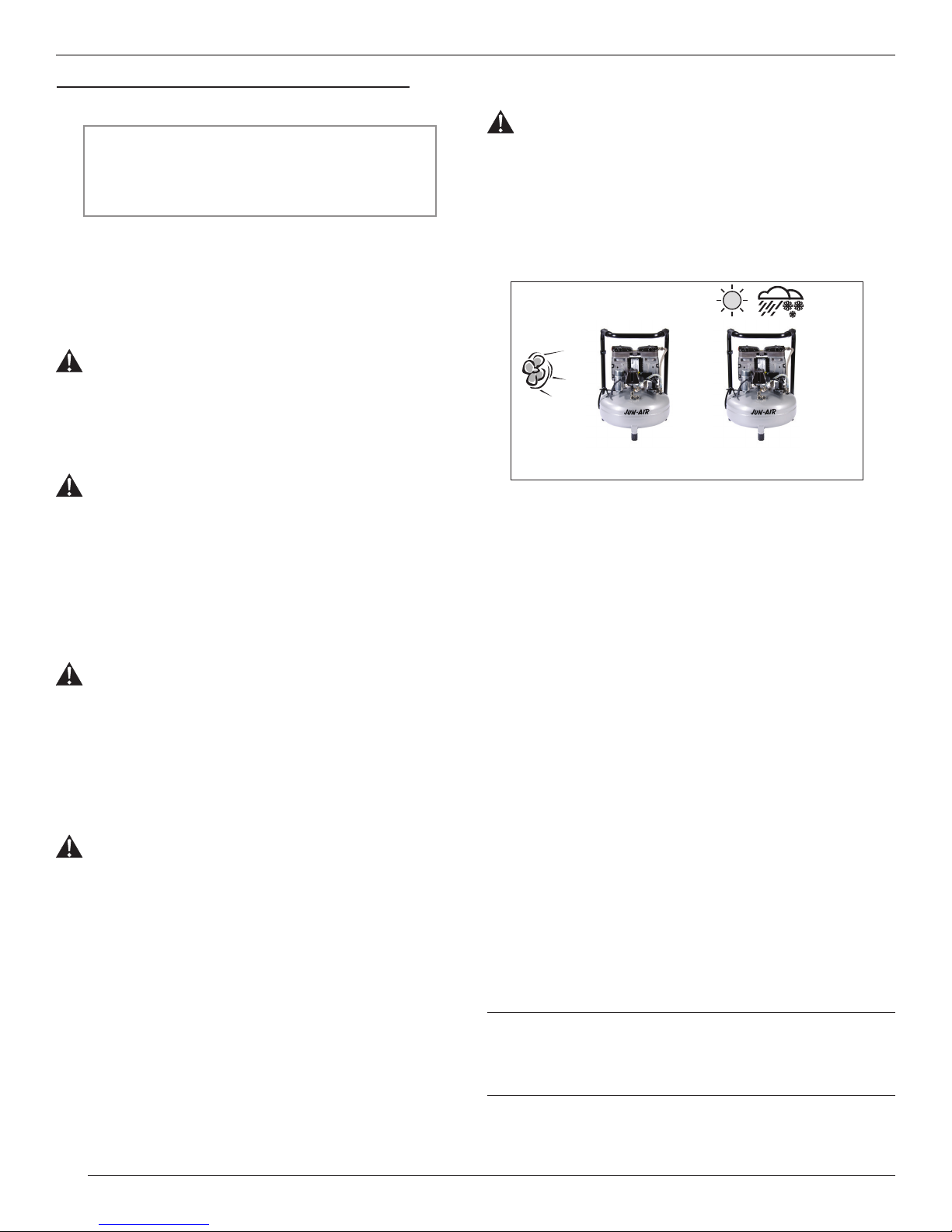
• Sufficient cooling from the surroundings is important. Place the system
in a dustfree, dry and cool, yet frostfree, room. Do not install in a closed
cupboard, unless adequate openings for ventilation are available on top
and bottom (minimum 500 cm²/77.5 in² each). If the system is placed
under a table, a minimum of 12 cm/5 in free height must be available
above the system or an opening of Ø30cm/11.8 inches, corresponding
to the top of the system, may be cut in the table. Ensure that the system
stands firmly on the floor.
• The intake air may be supplied from another place (for instance outside).
Ensure that hoses for the intake are sufficient to avoid performance loss
and that any alternate filter used has the same micron rating (50μm) as the
JUN-AIR intake filter.
Electrical installation
Warning!
Incorrect electrical connection may result in electric shock. The
electrical connection must be carried out in accordance with
local electrical regulations and by qualified electrical engineers.
Note!
Earthing of all AC models must be ensured during installation. The capacitor
must be earthed, as failure to do so may cause electric shock when touched.
Plug the system into an earthed socket of nominal voltage and ensure that
fusing is adequate.
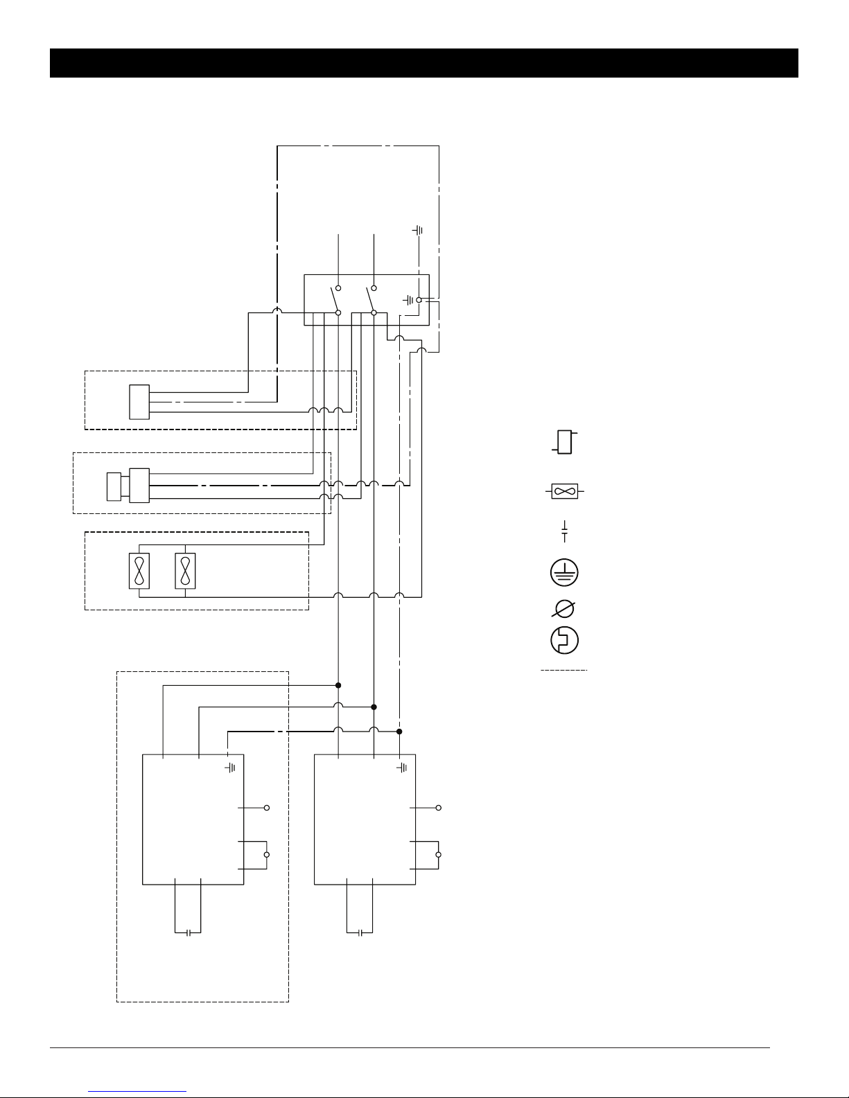
AC models
• For electrical connection, refer to schematic in back of this manual.
• Check system serial number label for frequency and voltage to ensure
that it corresponds to the voltage and frequency used for the system. The
voltage stated on the system plate: 120/240V (/) means that the system
can operate at 120V or 240V, but this requires recoupling of the internal
wiring from the electrical system (see the electrical diagrams). 220-230V
(-) means that the system may operate within the range of 220V to 230V
without recoupling of the internal wiring.
• Capicitor is wired to motor via terminal box on side of motor.
• Accessorries are wired through the system pressure switch.
Operation
• If the temperature of the system is extremely low (for instance after
transportation or stocking), allow system to get to room temperature before
switching on the system.
• Do not use system for compression of liquids and dangerous gasses,
such as petrol vapour and solvents.
Important
This system is only suitable for atmospheric air.
• Do not remove protection covers during operation as it may cause electric
shock or risk of other personal injury (ie: terminal box, pressure switch).
• Ensure that system is correct for air supply flow required, see Technical
Specifications.
• Open the outlet cock on the receiver and connect equipment.
Adjustment of pressure switch
Warning!
If maximum pressure is exceeded, reduced lifetime may result.
Contact JUN-AIR for information on operation at higher
pressure.
• All systems may run at 100% continuous operation, but 50% operation is
recommendable to prolong lifetime.
• The system should be sized so that the tank is capable of supplying air
100% of the time and the compressors only run at 50%.
• Do not lubricate the oil-less system with oil, as this will destroy important
components.
• Start the system using the 0/1 switch on the pressure switch. The system
will automatically switch off at the preset pressure. If the system does not
start it may be due to pressure in the receiver, and the system will then
start automatically when the pressure reduces to approx. 6 bar/87 psi.
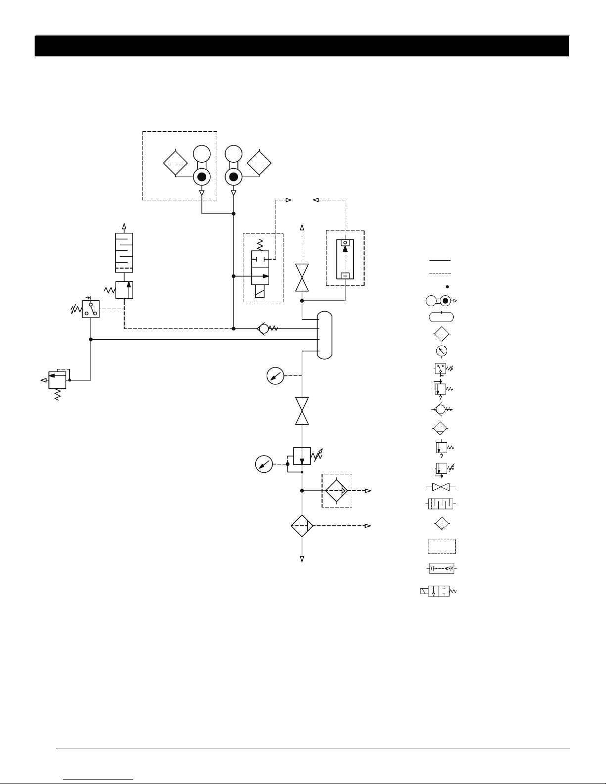
• Adjustment of pressure (see back of manual)
A: Max. pressure adjustment (cut-out)
B: Differential adjustment (cut-in)
The cut-in pressure (normally 6 bar) is set by adjustment of differential
screw B. Turn clockwise to reduce cut-in pressure. The cut-out pressure is
set by even adjustment of the two screws A. (Cut-in pressure + differential
= cut-out pressure). Turn clockwise to increase cut-out pressure. The
switch is normally factory set for operation at 6-8 bar (approx. 90-120 psi).
Fault finding and repair
Important!
Switch off and isolate from electrical supply before removing
any parts from the system. Empty air receiver of air before
dismantling parts of system unit’s pressure system.
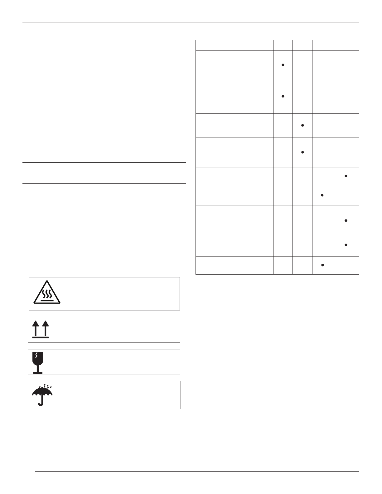
1. System does not start:
a) No power from mains. Check fuses and plug.
b) Breakage or loose joints in electrical connections.
c) Defective capacitor.
d) The thermal protection has switched off the pump due to overheating.
When cooled the pump will automatically turn on at a suitable
operation temperature. Go through the points in step 5.
e) The system has not been unloaded and there is back pressure. Make
sure that the system is unloaded each time it stops.
f) The pump is locked.
g) Pressure in the air receiver is too high for activation of the pressure
switch. The pressure switch makes circuit only when pressure has
dropped to preset start pressure. Empty receiver.
2. System does not start, makes a buzzing sound followed by a
clicking noise (cannot start against high pressure):
a) Leaky non-return valve. Remove the flexible pressure pipe and clean
to find out whether air leaks from the valve. If so, clean or replace.
3 System works, but pressure does not increase:
a) Intake filter clogged. Replace.
b) Leaks in fittings, tubes or pneumatic equipment. Check with soapy water
or by letting unit stay overnight with disconnected mains. Pressure drop is
not to exceed 1 bar.
c) Cups are worn out. Check and replace if neccessary.
d) Defective valve plate. Contact your JUN-AIR distributor.
e) Burr or failure in non-return valve which is creating a flow restriction.