JustFire H1501 User manual

TABLE OF CONTENTS
Patio Heater Safety Warnings -------------------------------------------
Part List & Hardware -------------------------------------------------------
Exploded View ---------------------------------------------------------------
Patio Heater Assembly ----------------------------------------------------
Leak Testing ------------------------------------------------------------------
Gas Requirement -----------------------------------------------------------
Connecting To a Gas Cylinder -------------------------------------------
Operating Instructions -----------------------------------------------------
Important Safety Rules ----------------------------------------------------
Maintenance -----------------------------------------------------------------
Servicing ----------------------------------------------------------------------
Storage ------------------------------------------------------------------------
Troubleshooting--------------------------------------------------------------
Technical Data ---------------------------------------------------------------
Guarantee ---------------------------------------------------------------------
Discard -------------------------------------------------------------------------
PATIO HEATER SAFETY WARNINGS
PLEASE READ THE INSTRUCTIONS CAREFULLY BEFORE INSTALLATION AND USE.
●This appliance must be used outdoors or in a well ventilated area, and should not be installed or used indoors.
●Change the gas cylinder in a well ventilated area, away from any inflammation sources.
●The cylinder must be stored outdoors or in a well ventilated area.
●Storage this appliance indoors is permissible only if gas cylinder is disconnected and removed from the
appliance.
●Do not move this appliance when in operation, or after it has been turned off before the temperature has cooled
down.
●Do not attempt to alter the appliance in any manner. Do not paint the radiant screen, control panel or reflector.
●Do not obstruct the ventilation holes of the cylinder housing.
●The appliance must be installed and gas cylinder stored in accordance with local gas fitting regulations.
●Shut off the valve at the gas cylinder or the regulator before moving the appliance.
●Repairs should be done by a qualified person.
●In case of violent wind, particular attention must be taken against tilting of the appliance.
●Check that the regulator seal is correctly fitted and able to fulfil its function.
●Close the gas supply at the valve of the gas cylinder or the regulator after use.
●Do not use this appliance until all connections have been leak tested.
!2
1-2
2-3
4
4-7
8
8
8
9
9
10
10
10
11
12
12
12

●In the event of gas leakage, the appliance shall not be used or if alight, the gas supply shall be shut off and the
appliance shall be investigated and rectified before it is used again.
●Checking the tubing or the flexible hose per month and each time the cylinder is changed.
●The tubing or the flexible hose must be changed within the prescribed intervals or within one year.
●The hose assembly must be replaced prior to the appliance being put into operation if there is evidence of
excessive abrasion or wear, or if the hose is damaged, and that the replacement hose assembly shall be that
specified by the manufacturer.
●The heater should be inspected before use and at least annually by a qualified service person. More frequent
cleaning may be required as necessary. It is imperative that control compartment, burners and circulating air
passageways of the appliance be kept clean.
●Shut off and check heater immediately if any of the following conditions exist:
□The smell of gas in conjunction with extreme yellow tipping of the burner flames.
□Heater does not reach a proper temperature. A temperature less than 5℃will cause restricted heat flow
and the appliance will not work properly.
□The appliance starts making popping noises during use (a slight popping noise is normal when the
appliance is extinguished).
●The regulator & hose assembly must be located out of pathways where people may trip over it or in area where
the hose will not be subject to accidental damage.
●Any guard or other protective device removed for servicing the heater must be replaced before operating the
heater.
●Children and adults should be warned of the hazards of high surface temperatures and should stay away to
avoid burns or clothing ignition.
●Young children and pets should be carefully supervised when they are in the area of the heater.
●Clothing or other flammable materials should not be hung from the appliance, or placed on or near the
appliance.
●Do not place articles on or against this appliance. Certain material or items when stored under or near this
appliance will be subjected to radiant heat and could be seriously damaged.
●Do not use or store flammable materials near this appliance.
●Do not spray aerosols in the vicinity of this appliance while it is in operation.
●Always maintain at least 0.9m clearance from combustible materials.
●Always position the appliance on a firm level surface. An amply ventilated area must have a minimum of 25% of
the surface area open. The surface area is the sum of the walls surface.
PATIO HEATER PART LIST
PART #
PART NAME
PICTURE
QTY
1
REFLECTOR
1
2
FLAME SCREEN
1
3
SUPPORT BAR - UPPER
4
!
!
!
!3

HARDWARE
4
MESH GUARD
4
5
GLASS TUBE
1
6
RUBBER RING
1
7
CHAIN (ASSEMBLED WITH
DOOR)
1
8
PLATE COVER
1
9
BURNER ASSEMBLY
10
REAR PAENL OF TANK
HOUSING
1
11
SUPPORT BAR – LOWER
4
12
SIDE PANEL OF TANK
HOUSING
2
13
DOOR OF TANK HOUSING
1
14
BOTTOM PLATE
1
!
!
!
!
!
MODEL H1507 DOESN’T INCLUDE THIS PART
!
!
!
!
!
!
PART #
PART NAME
PICTURE
QTY
DESCRIPTION
AA
M5 CAP NUT
4
TO CONNECT REFLECTOR AND
FLAME SCREEN
BB
M5 CREWS &
WASHER
60
M5 X 8 SCREW & M5 WASHER
!
!
!4

EXPLODED VIEW
!
PATIO HEATER ASSEMBLY
ASSEMBLY INSTRUCTIONS
●List of Required Tools: Philip Screwdriver
●Leak Detection Solution: one part detergent and three parts water
●Assemble all nuts and bolts loosely at first. Tighten all connections after completion of assembly.
This eases your work and increase the stability of the appliance.
●Before assembly, make sure all packing material and any transmit protection must be removed.
●Small deviations in equipment may occur. This is no lack of quality but subject to improvements.
CC
M5 F TAPPING
SCREWS & WASHER
18
ST4.2X9.5 SELF TAPPING
SCREWS & M5 WASHER
!
!5

●If any part is missing or damaged, do not attempt to assembly this product, Contact customer service for
replacement parts.
●Assembly should be performed on a flat, level, non-abrasive surface.
●ESTIMATED ASSEMBLY TIME: about 45 - 90 minutes.
STEP1: Connect and fix the 4 Support Bar – Lower (1) to Bottom Plate (14) and Plate Cover (8) by 32PCS M5
screws and washers(BB)
STEP 2: Lay down tank housing, fix the Burner
Assembly (9) to Pate Cover (8) by 4pcs M5
Screws and Washers (BB).
!!
!
!!
!6

STEP 3: Obliquely insert and attach 2pcs Side Panels (12) and 1pc Rear Panel (10) into tank housing using
18pcs M5 self-tapping screws and washers (CC). Best affix two opposite sides first, fastening the screws
diagonally.
Note: Do not close the door where is near to the control knob!
STEP 5: Attach Flame Screen (2) to the top of Support Bar-Upper (3) and fix the connection with 2pcs M5
screws and washers (BB), (See FigureⅠ, Ⅱ).
Repeat this step and connect Flame Screen (2) to other 3 sets Support Bars-Upper (3). (See Figure Ⅲ, Ⅳ)
STEP 6: Place Reflector (1) on the Flame Screen (2) and
fix the connection with 4pcs M5 CAP NUT (AA).
!
!
!
!
!
!7

STEP 7: Place the whole upper parts to top of tank housing assembly. Make sure
match the top ends of tank housing assembly with the bottom slot of Support Bar
– Upper (3). Match the threaded holes and fix each connection with 2pcs M5
Screws and Washers (BB)
STEP 8: Insert 6 projecting ends of
each Mesh Guard (4) into the seat
slots of Support Bar–Upper (3) as
shown in picture. Fix all Mesh Guards
(4) except the front side.
!
!
!
!
!
!
!
!
!
!8

LEAK TESTING
NEVER USE A NAKED FLAME TO CHECK FOR LEAKS.
NEVER LEAK TEST WHILE SMOKING.
The gas connections on this appliance are leak tested at the factory prior to
shipment.
This appliance needs to be periodically checked for leaks and an immediate
check is required if the smell of gas is detected.
●Make a soap solution using 1 part of liquid dish-washing soap to 3 parts
water. The soap solution can be applied with a soap bottle, brush, or rag
to the leak tested points shown in the figure above.
●The valve of the gas cylinder should be in the OFF position at this point of
the leak test. Once the soapy solution is applied to the gas connections,
the valve of the gas cylinder needs to be turned to the ON position.
●Soap bubbles will begin to form in the soapy solution if a leak is present.
●In case of a leak, turn off the gas supply. Tighten any leaking fittings, then turn the gas supply on and recheck.
GAS REQUIREMENTS
●The appliance must use an EN12864 or EN16129 approved gas regulator and CE approved gas hose with a
STEP 9: Fix Rubber Ring (6) into the bottom of Glass Tube (5). Insert the top end of glass tube into the bottom
hole of Flame Screen (2) as much as possible. Keep glass tube vertically and sit it in the hole of Plate Cover (8).
NOTE: GLASS TUBE IS FRAGILE PART, PLEASE HANDLE GLASS TUBE CAREFULLY AND SLOWLY!
STEP 10: Assemble Mesh Guard (4) in the front.
Loose 4pcs screws to keep 4pcs Guard Fastening
Plates down and firmly in place.
STEP 11: Insert the feet of door into the bottom slots.
Attach the Chain (7) to the hook of Burner Assembly (9)
and close the door.
Note: Model H1507 doesn’t take this Chain.
!
!
!
!
!
!
!9
Leak Test Point ①②③

length of 50cm (BS3212 and EN1763-1). Choose the proper regulator according to outlet pressure in the
technical table in page 14.
You will need to purchase suitable gas hose and regulator from your local gas dealer if the appliance does not
include gas hose and regulator.
●Never use a gas cylinder with a damaged body, valve, collar, or foot ring. A dented or rusty gas tank may be
hazardous and should be checked out by a gas supplier.
●Never connect this appliance to an unregulated gas source.
●When the appliance is not in use, turn the gas cylinder OFF.
●Always perform a leak test on gas connections whenever a cylinder is connected. If bubbles form in the leak
test solution, do not use. Never use a flame to test for leaks.
CONNECTING TO A GAS CYLINDER
●Recommended to use max.15kg or smaller gas cylinder (maximum height 65cm) refer to your gas supplier for
suitable gas cylinder.
●Approved gas regulator is used according to appliances categories and countries listed in data plate. Approved
flexible hose would be changed when the national conditions require it.
●Assembly of the tubing must be conducted by some qualified tuber of destination countries.
●Only change gas cylinders outdoors or in a well ventilated area away from naked flames and any other source
of ignition (candle, cigarettes, other flame producing appliance….).
●The gas cylinder must always be used in an upright position.
●Close the heater control knob by turning fully clockwise.
●Close the gas cylinder tap and then attach the regulator onto the gas cylinder.
●Tighten all connections firmly and with a spanner where appropriate. The cylinder should be located on the
cylinder base.
●Check for leaks at all joints using soapy water. If a leak is found, tighten the joint and then re-test.
OPERATING INSTRUCTIONS
BEFORE FIRST USE AND AFTER EVERY GAS CYLINDER CHANGE, GAS DELIVERY SYSTEM MUST BE
PURGED OF AIR BEFORE IGNITING! TO DO THIS, TURN THE CONTROL KNOB ANTI-CLOCKWISE TO THE
PILOT SETTING. PRESS KNOB IN AND HOLD FOR 3 MINUTES BEFORE ATTEMPTING IGNITION.
BATTERY REPLACMENT
Remove impulse ignition cap from Burner Assembly (J) by turning cap counterclockwise. Install 1 AAA battery.
Negative end of battery goes in first, then replace impulse ignition cap by turning cap clockwise.
TO LIGHT THE PILOT
●Check all connections prior to each use.
●Turn on main gas supply at source.
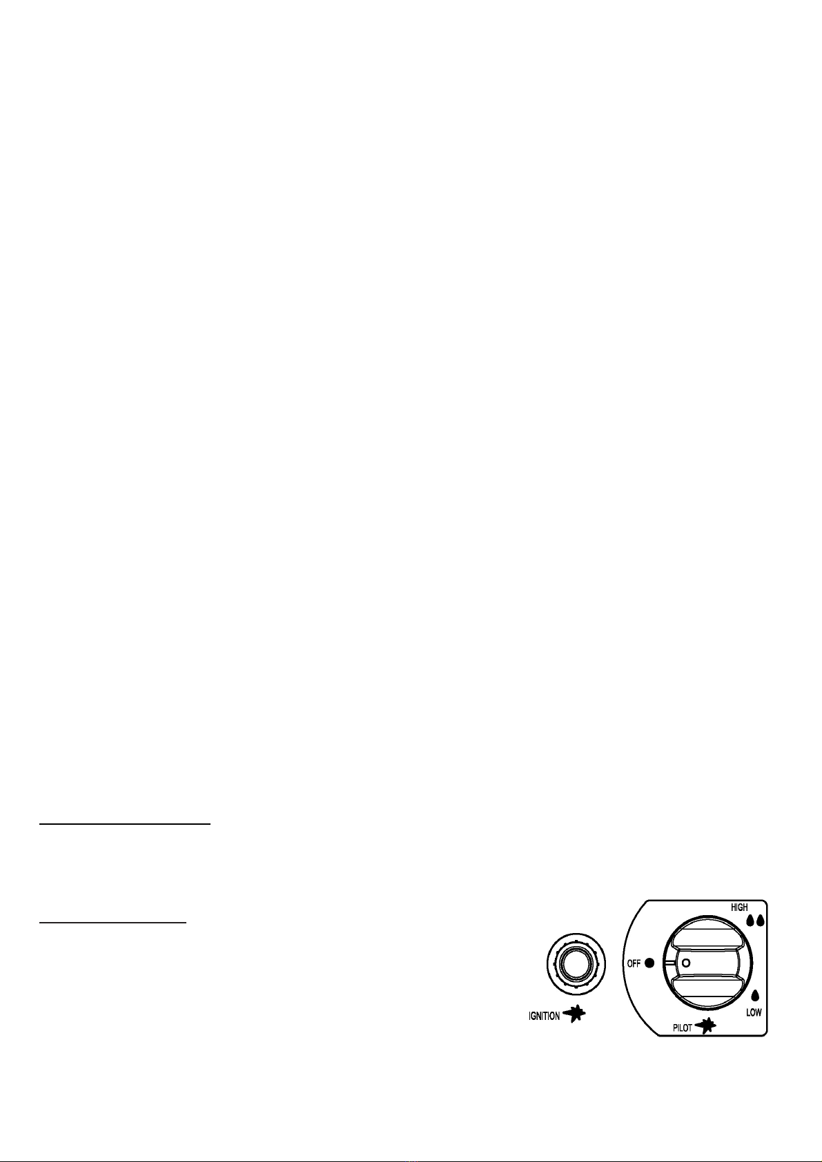
●Press to turn control knob anti-clockwise to PILOT, see right photo.
●Hold knob depressed, press IGNITION button repeatedly until pilot
flame is lit, then continue to hold the knob depressed for 10 seconds
until the pilot remains it after releasing knob.
●If pilot fails to ignite or alight, press to turn knob clockwise to OFF and repeat.
!10

TO LIGHT THE PATIO HEATER
●The pilot should be lit and the knob set to PILOT.
●Hold knob depressed gently and turn anti-clockwise to LOW.
●When mesh glows lit, turn knob clockwise from Low to HIGH as needed.
Note: The burner may be noisy when initially turned on. To eliminate excessive noise from the burner, turn
the control knob to the pilot position. Then turn the knob to the level of heat desired.
RE-LIGHTING
●Turn Control Knob to OFF.
●Wait at least 5 minutes, to let gas dissipate, before attempting to re-light pilot.
●Repeat the “Lighting” steps.
TO EXTINGUISH
●Hold knob depressed & turn the knob clockwise to 'OFF'
●Close the valve of the gas cylinder or the regulator after use.
●Close the gas bottle and allow this appliance to cool before moving the appliance.
Note: After use, some discoloration of the emitter screen is normal. Close regulator after use, allow the
appliance to cool before moving.
IMPORTANT SAFETY RULES
For use outdoors or in amply ventilated areas.
An amply ventilated area must have a minimum of 25% of the surface area open.
The surface area is the sum of the walls surface.
The use of this appliance in enclosed areas can be dangerous and is PROHIBITED.
Children and adults should be aware of the high operating temperatures of areas above the
post when operating this heater.
Children should be carefully supervised when in the vicinity of the heater.
NEVER hang anything, including clothes or any other flammable items, on this heater.
DO NOT operate this heater unless it is fully assembled with its reflector in place.
Respect the minimum clearances from combustible materials.
MAINTENANCE
To enjoy years of outstanding performance from your heater, make sure you perform the following maintenance
activities on a regular basis:
●Keep exterior surfaces clean.
●Use warm soapy water for cleaning. Never use flammable or corrosive cleaning agents.
●While washing your unit, be sure to keep the area around the burner and pilot assembly dry at all times. If the
gas control is exposed to water in any way, DO NOT try to use it. It must be replaced.
●Airflow must be unobstructed. Keep controls, burner and circulation air passageways clean. Signs of possible
blockage include:
■Gas odor with extreme yellow tipping of flame.
■Heater does NOT reach the desired temperature.
■Heater glow is excessively uneven.
!11

■Heater makes popping noises.
●Spiders and insects can nest in burner or orifices. This dangerous condition can damage the heater and render
it unsafe for use. Clean burner holes by using a heavy duty pipe cleaner. Compressed air may help clear away
smaller particles.
●Carbon deposits may create a fire hazard. If any carbon deposits develop, clean dome and engine with warm
soapy water.
Note: in a salt-air environment (such as near the sea), corrosion occurs more quickly than normal.
Frequently check the corroded areas and repair them promptly.
SERVICING
●Please consult your local dealer for servicing this appliance and replacement of its parts. The servicing of the
appliance shall be carried out only by authorised personnel.
●Caution: do not use unauthorized parts or components for this appliance, only use original equipment
replacement parts and components. The use of unauthorized parts or components will void the warranty and
can create an unsafe condition.
STORAGE
There is no limitation on the storage of the appliance indoors provided that the cylinder is removed from
the appliance.
Between uses:
●Turn control knob OFF
●Turn gas cylinder OFF
Store heater upright in an area sheltered from direct contact with inclement weather (such as rain, sleet, hail, snow,
dust and debris).
If desired, cover to protect exterior surfaces and to prevent build up in air passages.
Note: Wait until heater is cool before covering.
During periods of extended inactivity or when transporting:
●Turn control knob OFF.
●Disconnect gas cylinder and move to a secure, well ventilated location outdoors. DO NOT store in a location
that will exceed 50°C.
Store heater upright in an area sheltered from direct contact with inclement weather (such as rain, sleet, hail, snow,
dust and debris).
If desired, cover heater to protect exterior surfaces and to prevent build up in air passages.
Note: Wait until heater is cool before covering
TROUBLESHOOTING
IF THE PROBLEM IS
:
AND THIS CONDITION EXISTS:
THEN DO THIS:
Cylinder valve is closed
Open valve
Blockage in orifice or pilot tube
Clean or replace orifice or pilot tube
!12

Pilot won’t light
Air in the gas line
Open gas line and bleed it (pressing
control knob in) for not more than
1-2 minutes or until you smell gas
Low gas pressure
Gas cylinder low or empty
Igniter fails
Use match to light pilot, and obtain new
igniter and replace. ( See below pictures)
Pilot won’t stay lit
Dirt build up around pilot
Clean dirt from around pilot
Connection between gas valve and pilot
assembly is loose
Tighten connection and perform
leak test
Bad thermocouple
Replace thermocouple
Burner won’t light
Gas pressure is low
Replace gas cylinder
Blockage in orifice
Clear blockage
Control knob is not in "ON" position
Turn control knob to "ON" position
Burner flame is low !
Note: Do not operate
heater below
5℃(40°F)
Gas pressure is low
Replace gas cylinder
Outdoor temperature is greater than 5℃(40°F
) and tank is less than 25% full
Replace gas cylinder
Supply hose is bent or kinked
Straighten hose and perform leak test o
n hose
Control knob is fully " ON"
Turn control knob to "OFF", let it cool to
room temperature and check burner an
d orifices for blockage
Emitter glows
uneven !
Note: Bottom 2.5cm of
emitter normally does
not normally glow
Gas pressure is low
Replace gas cylinder
Base is not on a level surface
Place heater on a level surface
Heater not level
Level heater
Carbon build-up
Dirt or film on reflector and emitter
Clean reflector and emitter
Thick black smoke
Blockage in burner
Turn control knob to "OFF", let it cool to
room temperature and remove
blockage and clean burner inside and
outside.
!13

TECHNICAL DATA
1.9m Real flame patio heater
Model H1501 is 1.9m flame heater with stainless steel base
Model H1502 is 1.9m flame heater with powder coated steel base
Model H1505 is 1.9m flame heater with wicker base
Model H1507 is 1.9m flame heater with LED panels and LED lights
Heat input: ∑Qn(Hs)=11.2kW
Consumption: 815g/h
PIN: 0063CL7070
Warning
Read the instructions before using this appliance.
The appliance must be installed in accordance with instructions and local regulations.
The use of this appliance in enclosed areas can be dangerous and is PROHIBITED.
For use outdoors or in amply ventilated areas.
An amply ventilated area must have a minimum of 25% of the surface area open.
The surface area is the sum of the walls surface.
GUARANTEE
Any defect affecting the functionality of the appliance which becomes apparent within one year of its
purchase will be corrected by free repair or replacement provided that it has been used and
maintained in accordance with the instructions and has not been abused or misused in any way. Your
statutory rights are not affected. If it’s under guarantee, state where and when it was bought, and
include proof of purchase (e.g. till receipt).
In line with our policy of continuous product development we reserve the right to change product,
packaging and documentation specifications without notice.
DISCARD
At the end of the life of the appliance, please cast of the appliance according to the on that moment
applying regulations and guidelines.
Country Code
CH-ES-FR-GB-
GR- IE-IT-PT
BE-CY-CZ-DK-EE-FI-
GR-IT-LT-LV-MT-NL-
NO-SE-SI-SK-BG-RO-
TR
AT-CH-DE
PL
CZ-FR-
GB-GR-IE-
PT
AT-CH-
DE-NL
Gas Category
I3+(28-30/37)
I3B/P(30)
I3B/P(50)
I3B/P(37)
I3P(37)
I3P(50)
Type of Gas
Butane
Propane
Butane/
Propane / Mixture
Butane/
Propane /
Mixture
Butane/
Propane
/ Mixture
Propane
Propane
Gas pressure
28-30
mbar
37mbar
30mbar
50mbar
37mbar
37mbar
50mbar
Injector Marking
1.6
1.6
1.4
1.5
1.6
1.5
!14

IN THE EVENT OF ANY PROBLEM, PLEASE ALWAYS CONSULT YOUR LOCAL DEALER.
!
!15
This manual suits for next models
3
Table of contents