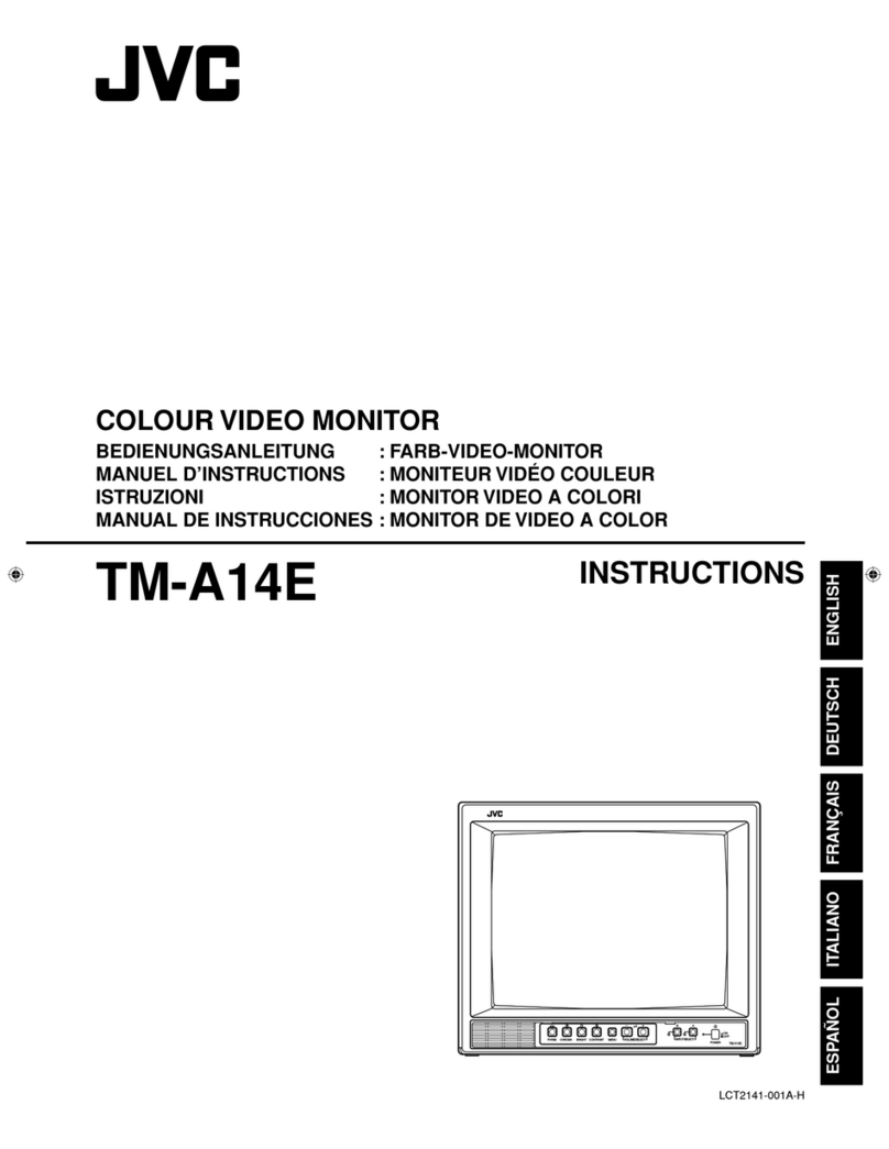
JVC TM-A101G/E User manual

No.51921
Dec. 2001
TM-A101G
1COPYRIGHT © 2001 VICTOR COMPANY OF JAPAN, LTD.
TM-A101G/E
TM-A101G/U
CONTENTS
SPECIFICATIONS ]]]]]]]]]]]]]]]]]]]]]]]]]]]]]]]]
]]]]]]]]]]]]]]]]]]]]]]]]]]]]]]]]]]]]]]]]]]]]]]]]]]]]]]]]]]]]]]]]
]]]]]]]]]]]]]]]]]]]]]]]]]]]]]]]]]]]]]]]]]]]]]]]]]]]]]]]]]]]]]
]]]]]]]]]]]]]]]]]]]]]]]]]]]]]]]]]]]]]]]]]]]]]]]]]]]]]]]]]]
]]]]]]]]]]]]]]]]]]]]]]]]]]]]] 2
ӠOPERATING INSTRUCTIONS (APPENDIX) ]]]]]]]]]]]]]]]]]]]]]]]]]]]]]]]]
]]]]]]]]]]]]]]]]]]]]]]]]]]]]]]]]]]]]]]]]]]]]]]]]]]]]]]]]]]]]]]]]
]]]]]]]]]]]]]]]]]]]]]]]]]]]]]]]]]]]]]]]
]]]]]]]]]]]]]]
]]]]]]] 1-1
SAFETY PRECAUTIONS ]]]]]]]]]]]]]]]]]]]]]]]]]]]]]]]]
]]]]]]]]]]]]]]]]]]]]]]]]]]]]]]]]]]]]]]]]]]]]]]]]]]]]]]]]]]]]]]]]
]]]]]]]]]]]]]]]]]]]]]]]]]]]]]]]]]]]]]]]]]]]]]]]]]]]]]]]
]]]]]]]]]]]]]]]]]]]]]]]]]]]]]]]]]]]]]]]]]]]]]]
]]]]]]]]]]]]]]]]]]]]]]] 3
FEATURES ]]]]]]]]]]]]]]]]]]]]]]]]]]]]]]]]
]]]]]]]]]]]]]]]]]]]]]]]]]]]]]]]]]]]]]]]]]]]]]]]]]]]]]]]]]]]]]]]]
]]]]]]]]]]]]]]]]]]]]]]]]]]]]]]]]]]]]]]]]]]]]]]]]]]]]]]]]]]]]]]]]
]]]]]]]]]]]]]]]]]]]]]]]]]]]]]]]]]]]]]]]]]]]]]]]]]]]]]]]]]]]]]]]]
]]]]]]]]]]]]]]]]]]]]]]]]]]]]]]]]]]
]]]]
]] 5
SPECIFIC SERVICE INSTRUCTIONS ]]]]]]]]]]]]]]]]]]]]]]]]]]]]]]]]
]]]]]]]]]]]]]]]]]]]]]]]]]]]]]]]]]]]]]]]]]]]]]]]]]]]]]]]]]]]]]]]]
]]]]]]]]]]]]]]]]]]]]]]]]]]]]]]]]]]]]]]]]]]]]]
]]]]]]]]]]]]]]]]]]]]]]]]]]
]]]]]]]]]]]]] 6
SERVICE ADJUSTMENTS ]]]]]]]]]]]]]]]]]]]]]]]]]]]]]]]]
]]]]]]]]]]]]]]]]]]]]]]]]]]]]]]]]]]]]]]]]]]]]]]]]]]]]]]]]]]]]]]]]
]]]]]]]]]]]]]]]]]]]]]]]]]]]]]]]]]]]]]]]]]]]]]]]]]]]]]
]]]]]]]]]]]]]]]]]]]]]]]]]]]]]]]]]]]]]]]]]]
]]]]]]]]]]]]]]]]]]]]] 11
ӠSTANDARD CIRCUIT DIAGRAM (APPENDIX) ]]]]]]]]]]]]]]]]]]]]]]]]]]]]]]]]
]]]]]]]]]]]]]]]]]]]]]]]]]]]]]]]]]]]]]]]]]]]]]]]]]]]]]]]]]]]]]]]]
]]]]]]]]]]]]]]]]]]]]]]]]]]]]]]]]]]]]]
]]]]]]]]]]
]]]]] 2-1
PARTS LIST]]]]]]]]]]]]]]]]]]]]]]]]]]]]]]]]
]]]]]]]]]]]]]]]]]]]]]]]]]]]]]]]]]]]]]]]]]]]]]]]]]]]]]]]]]]]]]]]]
]]]]]]]]]]]]]]]]]]]]]]]]]]]]]]]]]]]]]]]]]]]]]]]]]]]]]]]]]]]]]]]]
]]]]]]]]]]]]]]]]]]]]]]]]]]]]]]]]]]]]]]]]]]]]]]]]]]]]]]]]]]]]]]]]
]]]]]]]]]]]]]]]]]]]]]]]]]]]]]]]]]
]]
]35
BASIC CHASSIS
S2M1
SERVICE MANUAL
COLOUR VIDEO MONITOR

No.51921
TM-A101G
2
SPECIFICATIONS
Item Content
Dimension (Wѱ
ѱѱ
ѱHѱ
ѱѱ
ѱD) 222mmѱ220mmѱ316.3mm / 8-3/4”ѱ8-11/16”ѱ12-1/2”
Mass 6.8kg / 15.0lbs
Colour system PAL / NTSC 3.58
Picture tube
25cm / 9-7/8” measured diagonally
Flat-square type
90ѯdeflection, in-line gun
trio–dot type (phosphor dot-trio pitch 0.5 mm)
Effective screen size 175mmѱ137mm (WѱH) / 222mm (Diagonal)
6-15/16”ѱ5-7/16” (WѱH) / 8-3/4” (Diagonal)
Scanning frequency (H)15.734 kHz (NTSC)
15.625 kHz (PAL)
(V)59.94 Hz (NTSC)
50Hz (PAL)
Horizontal resolution 280TV line or more
Colour Temperature 6500K ; x = 0.313, y = 0.329
Power requirements 230V AC, 50/60 Hz [TM-A101G/E]
120V AC, 50/60 Hz [TM-A101G/U]
High Voltage 21.0kVϡ23.0kV
Power consumption 0.43A [TM-A101G/E]
0.61A [TM-A101G/U]
Signal input / output
VIDEO A Composite video signal : BNC terminal, 1V(p-p) 75negative sync
1 bridge-connected output possible with automatic termination
VIDEO B Composite video signal : BNC terminal, 1V(p-p) 75negative sync
1 bridge-connected output possible with automatic termination
AUDIO A Monaural, RCA pin, 500mV(rms)
High-impedance, 1-bridge-connected output posible
AUDIO B Monaural, RCA pin, 500mV(rms)
High-impedance, 1-bridge-connected output posible
REMOTE INPUT 1 line, RCA pin input
REMOTE ASPECT 1 line, RCA pin input
Audio power output 1W (Monaural)
Speaker 8cm roundѱ1, impedance 8
Operation temperature 0ϡ40ѵ(32ϡ104ѯ
F)
Operation humidity 20ϡ80% (non-condensing)
Design & specifications are subject to change without notice.

No. 51921
TM-A101G
3
SAFETY PRECAUTIONS
1. The design of this product contains special hardware, many
circuits and components specially for safety purposes. For
continued protection, no changes should be made to the
original design unless authorized in writing by the manufacturer.
Replacement parts must be identical to those used in the
original circuits. Service should be performed by qualified
personnel only.
2. Alterations of the design or circuitry of the products should not
be made. Any design alterations or additions will void the
manufacturer's warranty and will further relieve the
manufacturer of responsibility for personal injury or property
damage resulting therefrom.
3. Many electrical and mechanical parts in the products have
special safety-related characteristics. These characteristics are
often not evident from visual inspection nor can the protection
afforded by them necessarily be obtained by using
replacement components rated for higher voltage, wattage, etc.
Replacement parts which have these special safety
characteristics are identified in the parts list of Service manual.
Electrical components having such features are identified
by shading on the schematics and by (
) on the parts list
in Service manual. The use of a substitute replacement which
does not have the same safety characteristics as the
recommended replacement part shown in the parts list of
Service manual may caus e shock, fire, or other hazards.
4. Use isolation transformer when hot chassis.
The chassis and any sub-chassis contained in some products
are connected to one side of the AC power line. An isolation
transformer of adequate capacity should be inserted between
the product and the AC power supply point while performing
any service on some products when the HOT chassis is
exposed.
5. Don't short between the LIVE side ground and ISOLATED
(NEUTRAL) side ground or EARTH side ground when
repairing.
Some model's power circuit is partly different in the GND. The
difference of the GND is shown by the LIVE : () side GND,
the ISOLATED(NEUTRAL) : () side GND and EARTH : ()
side GND. Don't short between the LIVE side GND and
ISOLATED(NEUTRAL) side GND or EARTH side GND and
never measure with a measuring apparatus (oscilloscope etc.)
the LIVE side GND and ISOLATED(NEUTRAL) side GND or
EARTH side GND at the same time.
If above note will not be kept, a fuse or any parts will be broken.
6. If any repair has been made to the chassis, it is recommended
that the B1 setting should be checked or adjusted (See
ADJUSTMENT OF B1 POWER SUPPLY).
7. The high voltage applied to the picture tube must conform with
that specified in Service manual. Excessive high voltage can
cause an increase in X-Ray emission, arcing and possible
component damage, therefore operation under excessive high
voltage conditions should be kept to a minimum, or should be
prevented. If severe arcing occurs, remove the AC power
immediately and determine the cause by visual inspection
(incorrect installation, cracked or melted high voltage harness,
poor soldering, etc.). To maintain the proper minimum level of
soft X-Ray emission, components in the high voltage circuitry
including the picture tube must be the exact replacements or
alternatives approved by the manufacturer of the complete
product.
8. Do not check high voltage by drawing an arc. Use a high
voltage meter or a high voltage probe with a VTVM. Discharge
the picture tube before attempting meter connection, by
connecting a clip lead to the ground frame and connecting the
other end of the lead through a 10k2W resistor to the anode
button.
9. When service is required, observe the original lead dress.
Extra precaution should be given to assure correct lead dress
in the high voltage circuit area. W here a short circuit has
occurred, those components that indicate evidence of
overheating should be replaced. Always use the
manufacturer's replacement components.
10. Isolation Check
(Safety for Electrical Shock Hazard)
After re-assembling the product, always perform an isolation
check on the exposed metal parts of the cabinet (antenna
terminals, video/audio input and output terminals, Control
knobs, metal cabinet, screwheads, earphone jack, control
shafts, etc.) to be sure the product is safe to operate without
danger of electrical shock.
(1) Dielectric Strength Test
The isolation between the AC primary circuit and all metal parts
exposed to the user, particularly any exposed metal part having
a return path to the chassis should withstand a voltage of
1100V AC (r.m.s.) for a period of one second.
(. . . . Withstand a voltage of 1100V AC (r.m.s.) to an appliance
rated up to 120V, and 3000V AC (r.m.s.) to an appliance rated
200V or more, for a period of one second.)
This method of test requires a test equipment not generally
found in the service trade.
(2) Leakage Current Check
Plug the AC line cord directly into the AC outlet (do not use a
line isolation transformer during this check.). Using a "Leakage
Current Tester", measure the leakage current from each
exposed metal part of the cabinet, particularly any exposed
metal part having a return path to the chassis, to a known good
earth ground (water pipe, etc.). Any leakage current must not
exceed 0.5mA AC (r.m.s.).
However, in tropical area, this must not exceed 0.2mA AC
(r.m.s.).
z
zz
zAlternate Check Method
Plug the AC line cord directly into the AC outlet (do not use a
line isolation transformer during this check.). Use an AC
voltmeter having 1000 ohms per volt or more sensitivity in the
following manner. Connect a 150010W resistor paralleled
by a 0.15F AC-type capacitor between an exposed metal
part and a known good earth ground (water pipe, etc.).
Measure the AC voltage across the resistor with the AC
voltmeter. Move the resistor connection to each exposed metal
part, particularly any exposed metal part having a return path to
the chassis, and measure the AC voltage across the resistor.
Now, reverse the plug in the AC outlet and repeat each
measurement. Any voltage measured must not exceed 0.75V
AC (r.m.s.). This corresponds to 0.5mA AC (r.m.s.).
However, in tropical area, this must not exceed 0.3V AC
(r.m.s.). This corresponds to 0.2mA AC (r.m.s.).
0.15
F AC-TYPE
1500
10W
GOOD
EARTH
GROUND
PLACE THIS PROBE
ON EACH EXPOSED
METAL PART
AC VOLTMETER
(HAVING 1000
/V,
OR MORE SENSITIVITY)
11. High voltage hold down circuit check.
After repair of the high voltage hold down circuit, this circuit
shall be checked to operate correctly.
See item "How to check the high voltage hold down
circuit".
A V
This mark shows a fast
operating fuse, the
letters indicated below
show the rating.
POWER CORD
REPLACEMENT W ARNING.
Connecting the white line side of power
cord to “WHT” character side.

No. 51921
TM-A101G
4
SAFETY PRECAUTIONS
1. The design of this product contains special hardware and many
circuits and components specially for safety purposes. For
continued protection, no changes should be made to the original
design unless authorized in writing by the manufacturer.
Replacement parts must be identical to those used in the original
circuits. Service should be performed by qualified personnel only.
2. Alterations of the design or circuitry of the product should not be
made. Any design alterations or additions will void the
manufacturer's warranty and will further relieve the manufacturer
of responsibility for personal injury or property damage resulting
therefrom.
3. Many electrical and mechanical parts in the product have special
safety-related characteristics. These characteristics are often not
evident from visual inspection nor can the protection afforded by
them necessary be obtained by using replacement components
rated for higher voltage, wattage, etc. Replacement parts which
have these special safety characteristics are identified in the Parts
List of Service Manual. Electrical components having such
features are identified by shading on the schematics and by ()
on the Parts List in the Service Manual. The use of a substitute
replacement which does not have the same safety characteristics
as the recommended replacement part shown in the Parts List of
Service Manual may caus e shock, fire, or other hazards.
4. The leads in the products are routed and dressed with ties, clamps,
tubing’s, barriers and the like to be separated from live parts, high
temperature parts, moving parts and / or sharp edges for the
prevention of electric shock and fire hazard. When service is
required, the original lead routing and dress should be observed,
and it should be confirmed that they have been returned to normal,
after re-assembling.
WARNING
1. The equipment has been designed and manufactured to meet
international safety standards.
2. It is the legal responsibility of the repairer to ensure that these
safety standards are maintained.
3. Repairs must be made in accordance with the relevant safety
standards.
4. It is essential that safety critical components are replaced by
approved parts.
5. If mains voltage selector is provided, check setting for local
voltage.

No. 51921
TM-A101G
5
FEATURES
MAIN MICOM (IC731) PIN ARRANGEMENT
PORT NUMBER PIN NAME PORT NUMBER PIN NAME
1 H SYNC 27 VDD
2 V SYNC 28 OSC2
3NC 29OSC1
4 V CENTER 30 RESET
5NC 31NC
6 A VOLUME 32 NC
7 CUTOFF 33 KEY IN3
8 COMB SWITCH 34 KEY IN2
9 POWER ON/OFF 35 KEY IN1
10 AUDIO MUTE 36 SDA2
11 ASP REM 37 SDA1
12 NC 38 SCL2
13 Y/C SELECT 39 SCL1
14 POWER LED 40 NC
15 B1 PROTECT 41 NTSC / 0TH
16 REMOCON 42 SECAM / 0TH
17 P CHK 43 VIDEO B
18 INP REM 44 VIDEO A
19 VIDEO A MUTE 45 BUS FREE
20 VIDEO B MUTE 46 X RAY
21 Y/C MUTE 47 SDA3
22 NC 48 SCL3
23 NC 49 YS
24 X IN 50 B
25 X OUT 51 G
26 VSS 52 R
I2C BUS FLOW CHART (SCL1/SDA1, SCL2/SDA2)
SCL1
SDA1
SCL2
SDA2
IC731
Micro
Computer
IC732
Memory
IC201
Video Processor
910
39
37
38
36
65

No.51921
TM-A101G
6
SPECIFIC SERVICE INSTRUCTIONS
DISASSEMBLY PROCEDURE
CAUTION
Even with the power switch off, some parts of this unit are live. Be
sure to disconnect the power plug from the AC outlet before
disassembly and reassembly.
REMOVING THE TOP COVER
1. As shown in Fig.2, remove the 4screws marked #.
2. Remove the 4screws marked $.
3. Slightly spread the bottom of the top cover.
4. Shift the cover rearward and raise it upward to remove it.
REMOVING THE REAR PANEL
zAfter removing the top cover.
1. Remove the 4screws marked %.
2. Shift the top portion of the rear panel slightly rearward and raise it
upward to remove it.
REMOVING THE TERMINAL BRACKET
zRemove the top cover and rear panel.
1. Remove the 4screws marked &.
2. Remove the screw marked 'attached the FBT with the
terminal bracket.
3. As shown in Fig.1, remove the screws marked (and ). these
screws attached the earth wires to terminal bracket.
(See the “Caution about the earth wire” as shown Fig.1)
4. Slightly shift the terminal bracket rearward and raise it upward to
remove it.
REMOVING THE CHASSIS BASE
zRemove the top cover, rear panel and terminal bracket.
1. As shown in Fig.3, while pushing raise the claw marked *,
withdraw the chassis base toward you.
2. Follow the same steps when removing the other hand chassis
base.
REMOVING THE BOTTOM COVER
zRemove the chasssis base.
1. Set the CRT front surfase downward, and stand the bottom cover
to facing it toward you.
At this time, care must be exercised not to damage the front panel
and CRT surface.
2. As shown in the Fig.2, remove the 2screws marked ,.
3. Slightly raise the bottom cover, and then pull it out to upward.
REMOVING THE SPEAKER
zRemove the top cover.
1. Slightly spread the claws of the speaker holder, and pull up the
speaker to remove it.
CHECKING THE PW BOARD
To check the PW board from back side.
(1) Remove the chassis base and the other PW boards.
(2) Erect the chassis base vertically so that you can easily check the
PW board from back side.
CAUTION
zWhen erecting the chassis base, be careful so that there will be
no contacting with the other PW board.
zBefore turning on power, make sure that the CRT earth wire
and the other connectors are properly connected.
WIRE CLAMPING AND CABLE TYING
1. Be sure to clamp the wire.
2. Never remove the cable tie used for tying the wires together.
Should it be inadvertently removed, be sure to tie the wires with a
new cable tie.
Caution about Earth Wire
Befor turning on power, make sure that the earth wire (green
colour) are properly connected to the terminal bracket by the
screw (
((
(and )
))
).
EARTH WIRE
'
''
'
(
((
(
)
))
)
TERMINAL BRACKET
Fig.1

No.51921
TM-A101G
7
FRONT PANEL ASS’Y
CRT SOCKET PWB
TOP COVER
$
$$
$
CRT
$
$$
$
#
##
#
(CLAW)
CHASSIS
BASE
SPEAKER
SIGNAL PWB
MAIN PWB 1/2
(POWER&DEF. Bolck)
FBT
MAIN PWB 2/2
FRONT
CONTROL
Block
)
))
)
(
((
('
''
'
&
&&
&
TERMINAL BRACKET
%
%%
%
REAR PANEL
POWER CORD
BOTTOM COVER
,
,,
,
CHASSIS
BASE
Fig.2
Fig.3
*
**
*

No. 51921
TM-A101G
8
REPLACEMENT OF MEMORY IC
1. MEMORY IC
This model uses memory IC. In the memory IC, memorized data
for correctly operating for the video-chroma, deflection and the
other control circuits.
When replacing memory IC, be sure to use the IC written with
the initial values of data.
2. PROCEDURE FOR REPLACING MEMORY IC
(1) Power off
Turn the power off and unplug the power plug from the AC
outlet.
(2) Replace IC
Be sure to use the memory IC written with the initial setting
data.
(3) Power on
Connect the power plug into the AC outlet and turn the
power on.
(4) Check and set SET-UP MENU items
1) Press the MENU key and the CHROMA/PHASE key
simultaneously.
2) The SET-UP MENU screen (Fig. 1) will be displayed.
3) Check the setting value of the each item of the SET-UP
MENU. If the value is different, select the item and set the
correct value.
4) Press the
MENU key, and return to the normal screen.
(5) Check and set MENU items
Press the MENU key and check the setting value of the each
item. If the value is different, select the item and set the
correct value.
(6) Adjust the front control items
Adjust the CHROMA, PHASE, CONTRAST and BRIGHT.
Not all items can be adjusted as expected if the signal has
not been input correctly in the adjustments.
(7) Confirm the items of SERVICE MENU
Confirm the each item of the SERVICE MENU. Refer to the
corresponding page to operate the SERVICE MENU.
SIGNAL BLOCK
WHITE BALANCE BLOCK
DEFLECTION BLOCK
CONTROL BLOCK
< BLOCK SELECT >
SIG W/B DEF
CNTL
EXIT
SERVICE MENU
<BLOCK SELECT> SCREEN
SET-UP MENU
< SET-UP MENU>
EXIT
H.POSITION :00
WHITE BALANCE
CONTROL LOCK : OFF
STATUS DISPLAY :ON
INPUT REMOTE :OFF
ASPECT REMOTE :OFF
Fig.1
Ο
ΟΟ
ΟCURSOR
Display with the current adjusting item. Operate with the
CHROMA/PHASE key and CONTRAST/BRIGHT key.
Π
ΠΠ
ΠSETTING ITEM
The items of setting
Ρ
ΡΡ
ΡSETTING VALUE
Adjust each item of SET-UP MENU with the VOLUME/
SELECT (ҥ
ҥҥ
ҥor Ҥ
ҤҤ
Ҥ)key.
FUNCTION DISPLAY
When you move the cursor to select the item, the function
display changes the illustration.
Σ
ΣΣ
ΣOPERATION KEY ARRANGEMENT
In the SERVICE MENU, the original key operation by the
front panel replaced with the displayed function.
1
11
1
2
22
2 3
33
3
4
44
4
5
55
5

No. 51921
TM-A101G
9
INITIAL SETTING OF THE SET-UP MENU TABLE
Setting item Setting content / Range Initial setting value
H. POSITION -05 ϡ+05 00
CUTOFF (R / G / B) -09 ϡ+09 00
WHITE BALANCE
DRIVE (R / B) -09 ϡ+09 00
CONTROL LOCK OFF
STATUS DISPLAY ON
INPUT REMOTE OFF
ASPECT REMOTE OFF
INITIAL SETTING OF THE MENU SCREEN TABLE
Setting item Setting content / Range Initial setting value
SHARPNESS 00 ϡ+05 03
COLOUR SYSTEM AUTO NTSC PAL AUTO
ASPECT RATIO 4-3 16-9 4-3
INITIAL SETTING OF FRONT PANEL CONTROLS
Control item Initial setting value
INPUT SELECT A
CHROMA 00
PHASE 00
CONTRAST 00
BRIGHT 00
VOLUME 20
ON OFF
ON OFF
ON OFF
ON OFF

No. 51921
TM-A101G
10
BLOCK SELECT ADJUSTMENT ITEM
SIGNAL BLOCK
SERVICE ITEM CONTENTS
S01 BRIGHT
S02 CONTRAST
S03 CHROMA(PAL)
S04 CHROMA(NTSC)
S05 CHROMA(SECAM)
S06 PHASE(NTSC)
S07 BRIGHT(16:9)
S08 CONTRAST(16:9)
WHITE BALANCE
SERVICE ITEM CONTENTS
W01 R CUTOFF
W02 G CUTOFF
W03 B CUTOFF
W04 R DRIVE
W05 B DRIVE
CONTROL BLOCKȪ
ȪȪ
ȪThese are fixed values. Don’t adjust them.ȫ
ȫȫ
ȫ
SERVICE Number ITEM SERVICE Number ITEM
C01 MODEL C29 REMOCON
C02 UPPER C30 S-FIELD
C03 BRIGHT POINT LOWER C31 SDC ATT
C04 UPPER C32 DEMP F0
C05 CONTRAST POINT LOWER C33 V. ID. SW
C06 UPPER C34 S. KILL
C07 CHROMA POINT LOWER C35 BELL. F0
C08 UPPER C36 ABL. GAIN
C09 PHASE POINT LOWER C37 ABL. POINT
C10 OSD HORIZONTAL POSITION C38 TRAP SW (NTSC)
C11 OSD VERTICAL FREQUENCY (50Hz) C39 TRAP SW (PAL)
C12 OSD VERTICAL FREQUENCY (60Hz) C40 TRAP Q (NTSC)
C13 VERTICAL DELAY (NTSC) C41 TRAP Q (PAL)
C14 VERTICAL DELAY (PAL) C42 TRAP F0(NTSC)
C15 VERTICAL DELAY (SECAM) C43 TRAP F0(PAL)
C16 VERTICAL DELAY (BLACK AND WHITE) C44 TOF SW (NTSC)
C17 S DELAY (NTSC) C45 TOF SW (PAL)
C18 S DELAY (PAL) C46 TOF Q (NTSC)
C19 S DELAY (SECAM) C47 TOF Q (PAL)
C20 S DELAY (BLACK AND WHITE) C48 TOF F0 (NTSC)
C21 BRIGHT (VERTICAL) C49 TOF F0 (PAL)
C22 SHARP (CENTER VALUE) C50 APA (V. NTSC)
C23 V-GUARD C51 APA (V. PAL)
C24 HOUR METER C52 APA (V. SECAM)
C25 AFC MODE C53 APA (Y/C, B/W)
C26 BURST (NTSC / PAL) C54 R-Y BLACK OFFSET
C27 BURST (SECAM) C55 B-Y BLACK OFFSET
C28 COLOUR SYSTEM C56 CONTRAST CONTROL
DEFLECTION BLOCK
SERVICE ITEM CONTENTS
D01 HORIZONTAL POSITION
D02 VERTICAL SIZE
D03 VERTICAL SIDE PIN CORRECTION
D04 VERTICAL CENTER
D05 VERTICAL LINEARITY
In addition to the ones listed above, the following DEFLECTION BLOCK are
also available.
50Hz / 4:3 D01ϡD05
60Hz / 4:3 DA1ϡDA5
50Hz / 16:9 DB1ϡDB5
60Hz / 16:9 DC1ϡDC5
SCREEN DISPLAY
INPUT SIGNAL
V. FREQ / ASPECT

No.51921
TM-A101G
11
SERVICE ADJUSTMENTS
BEFORE STARTING
SERVICE ADJUSTMENT
1. Confirm the proper AC power voltage is being supplied.
2. Supply power to the set and measuring instruments and allow to
warm up for at least 30 minutes.
3. The setting is made on basis of the initial setting values. The
setting values which adjust the screen to the optimum condition
can be different from the initial setting values.
4. Use care not to disturb controls and switches not mentioned in
the adjustment items.
MEASURING INSTRUMENTS AND
STANDARD SIGNAL
DC voltmeter (digital voltmeter)
Oscilloscope
Signal generator (PAL/NTSC systems)
Colour analyser
High voltage meter
The wave form of signals refer following figure.
ADJUSTMENT ITEMS
FOCUS AND SCREEN
ADJUSTMENT HOLES
The FOCUS and SCREEN adjustment holes are on the side
panel.
[CAUTION]
Be sure to use a non-metalic driver for adjusting there VRs.
A metalic driver can cause damage by shorting.
STANDARD VIDEO SIGNAL (PAL / NTSC COLOUR BAR)
0.525Vb-w
0% SETUP
BURST
PAL : 0.3V(p-p)
NTSC : 0.286V(p-p)
75% saturation
A
djustment holes
Upper : FOCUS
Lower : SCREEN
Checking of B1 voltage Chroma adjustment (PAL, NTSC)
Checking of High voltage Phase adjustment (NTSC)
Focus adjustment Horizontal center adjustment
White Balance (Low Light) adjustment Horizontal size center adjustment
White Balance (High Light) adjustment Vertical center adjustment
Bright adjustment Vertical size adjustment
Contrast adjustment Vertical side pin cushion and linearity
adjustment

No.51921
TM-A101G
12
ADJUSTMENT LOCATIONS
B
U
HV
CN001
POWER SW
MAIN PWB
2/2
(FRONT CONTROL Block)
FRONT
MENU +(UP) -(DOWN) CONTRAST
/BRIGHT
CHROM
A/PHASE
VOLUME
/SELECT
VIDEO A
IND./SW
VIDEO B
IND./SW
POWER
IND./SW
V CENTER SW
S401
S1
FUSE
F901
DEG
AC
S901
E2
MAIN PWB
1/2
(POWER & DEF. Block)
FRONT
SIGNAL PWB
TO CRT SOCKET PWB
TERMINAL BRACKET
(Earth wire)
FBT
TO DEF YOKE
L502
H. SIZE COIL
1:GND
2:X-RAY2
3:X-RAY1
4:NC
5:TP-91(B1)
SW
LED
SW
LED
DY
B
: FOCUS VR
: SCREEN VR
UPPER
LOWER

No.51921
TM-A101G
13
TP-E
TP-47B
E1
S
SPEAKER
Y
CRT SOCKET PWB (SOLDER SIDE)
Y
TP-47G
U
CRT EARTH WIRE
(BRAIDED ASS'Y)
CN001
UPPER
SIGNAL PWB
UPPER
TO MAIN PWB
VIDEO A
VIDEO B
AUDIO A
AUDIO B
REMOTE
(INPUT/ASPECT)
SHIELD CASE

No. 51921
TM-A101G
14
BASIC OPERATION OF SERVICE MENU
1. SERVICE MENU ITEMS
With the SERVICE MENU, various settings can be made, and they are broadly
classified in the following items of adjustments. It is no requirement for adjustment the
portion of the DEFLECTION BLOCK and CONTROL BLOCK.
SIGNAL BLOCK ]]]]]]]]]]]]]] This block adjusts the data of the various signal
circuit controls.
WHITE BALANCE BLOCK]]] This block adjusts the data of the WHITE
BALANCE adjustment.
DEFLECTION BLOCK]]]]]]]] This block adjusts the data of the DEFLECTION
circuit.
CONTROL BLOCK ]]]]]]]]]]] This block adjusts the whole of the systems
(This block is a fixed value. Don’t adjust it.)
2. BASIC OPERATION OF THE SERVICE MENU
(1) HOW TO ENTER THE SERVICE MENU
ΟPress MENU key and VOLUME/SELECT + (UP) key simultaneously (Fig. 1).
The letter “S” appears at the upper left of the screen (Fig. 2).
ΠWhile displaying the letter “S”, press MENU key and CHROMA/PHASE key
simultaneously (Fig.1).
The screen display “PLEASE DON’T TOUCH” (Fig. 3).
ΡWHILE displaying the letters above-mentioned, press VOLUME/SELECT
+ (UP) key or – (DOWN) key to display the SERVICE MENU as shown in
Fig. 4.
If above-mentioned steps or state continues for more than 5 seconds without
a further operation, the display extinguishes and the mode is released.
S
Fig. 2
PLEASE, DON'T TOUCH !
Fig. 3
SERVICE MENU
SIGNAL BLOCK
WHITE BALANCE BLOCK
DEFLECTION BLOCK
CONTROL BLOCK
< BLOCK SELECT >
SIG W/B DEF CNTL EXIT
Fig. 4
BLOCK SELECT ITEM
FUNCTION DISPLAY
(Indication of key operation
in SERVICE MENU)
Fig.1
3
2
1

No. 51921
TM-A101G
15
(2) OPERATION OF <BLOCK SELECT> SCREEN
While the SERVICE MENU <BLOCK SELECT> screen is displaying, in
accordance with the key control display (Function Display) at the lower side
of the screen, be able to operate the various items (Fig. 5).
< For example as following, explaining about SIGNAL BLOCK key
operations. >
(3) SELECT THE SERVICE NUMBER
Press the CHROMA/PHASE or CONTRAST/BRIGHT key to select the
service number.
(4) ADJUSTMENT DATA OPERATION
Press the VOLUME/SELECT + (UP) key to change the setting value in the
+ direction.
Press the VOLUME/SELECT – (DOWN) key to change the setting value in
the - direction.
(5) EXIT SERVICE MENU
When adjustments are completed, press MENU key then return to the
BLOCK SELECT screen. Again press MENU key then return to the normal
screen.
SIGNAL BLOCK
WHITE BALANCE BLOCK
DEFLECTION BLOCK
CONTROL BLOCK
< BLOCK SELECT >
SIG W/B DEF CNTL EXIT
CNTL
DEFW/B
SIG EXIT
< Function Display >
< Front Panel Key Arrangement >
SIGNAL BLOCK]]]]]]]]]]]]] Press CHROMA/PHASE key. Enter to
signal circuit adjustment mode.
WHITE BALANCE BLOCK]]]] Press CONTRAST/BRIGHT key. Enter
to white balance setting adjustment
DEFLECTION BLOCK]]]]]]]] Press VOLUME/SELECT –(DOWN) key.
Enter to deflection circuit adjustment
CONTROL BLOCK ]]]]]]]]]] Press VOLUME/SELECT +(UP) key.
Enter to system whole setting mode.
EXIT ]]]]]]]]]]]]]]]]]]]]]]] Press MENU key. Return to normal
screen mode.
Fig. 5
SERVICE MENU
EXIT ʷ
ʝ
ʝ
ʝ
ʝ
ʝ
ʝ
ʧ
ʧ
ʧ
<S01 >
Service number indication
Setting value indication
< Function display >
Service number select key
Data operate (inc/dec) key
< Front Panel Key Arrangement > Fig. 6
Exit key

No. 51921
TM-A101G
16
3. HOW TO OPERATE EACH SERVICE MENU ITEMS
ӕSIGNAL BLOCK
ΟIn the <BLOCK SELECT> screen , press the CHROMA/PHASE key.
ΠThen SIGNAL BLOCK adjustment mode screen is displayed (Fig. 7).
ΡThe original front key function replaced with the different function
displayed at the lower side of the screen as shown below.
Refer to the illustration given below, the function about each key in
this mode.
In this mode, CONTRAST/BRIGHT key is the switch of the screen
display. If necessary, you can shut off the display. Carefully, values of
adjustment items are changed while shut off the screen display.
ΣPress the MENU key, then exit the SIGNAL BLOCK screen to return
to the <BLOCK SELECT> screen.
ӕWHITE BALANCE BLOCK
ΟIn the <BLOCK SELECT> screen, press the CONTRAST/BRIGHT
key.
ΠThen WHITE BALANCE menu screen is displayed (Fig. 8).
ΡIn this case, key function is replaced as shown below. There are
several modes of WHITE BALANCE adjustment. Select the various
WHITE BALANCE mode from this menu screen.
Press the MENU key few times, then exit from the WHITE BALANCE
BLOCK screen to return to the <BLOCK SELECT> screen.
WHITE BALANCE BLOCK
CUT OFF : CUTO
DRIVE : DRV
CUTO
DRV W01 W05 EXIT
Fig. 8
CUTO
DRV W01 W05 EXIT
< Function Display >
Select the CUTOFF mode
Select the DRIVE mode
Select the various item modes
A
djustment mode exit key
< Front Panel Key Arrangement >
SIGNAL BLOCK
DISP
EXIT
ʷ
ʝ
ʝ
ʝ
ʝ
ʧ
ʧ
ʧ
< S01 >
Fig. 7
DISP EXIT
ʷ
ʝ
ʝ
ʝ
ʝ
ʧ
ʧ
ʧ
< S01 >
< Function Display >
Select the Service Number
Display on/ off switch
Data operate (inc/dec) key
A
djustment mode exit key
Service number indicated
Setting value indicated
< Front Panel Key Arrangement >

No. 51921
TM-A101G
17
[ WHITE BALANCE Adjustment : METHOD 1 ]
Accordance with the screen display, select the each WHITE BALANCE mode
following below.
CUTOFF adjustment mode (Low light adjustment)
ΟIn the WHITE BALANCE menu screen, press the CHROMA/PHASE key to
enter to the CUTOFF adjustment mode (Fig. 9). In this case, key function is
replaced as shown below.
ΠWhenever press the CHROMA/PHASE key, change the adjustment colour
of R, G and B.
ΡThe single horizontal line service screen appears if press the
CONTRAST/BRIGHT key (Fig. 10).
zRefer to the “Low-Light adjustment” corresponding page about detailed
adjustment steps.
DRIVE adjustment mode (HIGH LIGHT)
ΟIn the WHITE BALANCE menu screen, press the CONTRAST/BRIGHT
key to enter to the DRIVE adjustment mode (Fig. 11). In this case, key
function is replaced as shown below.
ΠWhenever press the CHROMA/PHASE key, change the “R DRIVE” or “
B DRIVE” adjustment mode.
ΡCONTRAST/ BRIGHT key is the switch of the screen display. If necessary,
you can shut off the display. Carefully, values of adjustment items are
changed while shut off the screen display.
zRefer to the “High-Light adjustment” corresponding page about detailed
adjustment steps.
CUTOFF ADJUSTMENT SCREEN
R CUTOFF ŅŅЅ***
RGB SERV EXIT
Fig. 9
SINGLE HORIZONTAL LINE
Fig. 10
single horizontal line
RGB
SERV
EXIT
< Function Display >
< Front Panel Key Arrangement >
DRIVE ADJUSTMENT SCREEN
R DRIVE Ѕ***
R-B DISP EXIT
Fig. 11
R-B
DISP
EXIT
< Function Display >
< Front Panel Key Arrangement >
Select the R, G or B mode
Display 1H line switch
Data operate (inc/dec) key
A
djustment mode exit key
Select the R or B mode
Display on/off switch
Data operate (inc/dec) key
A
djustment mode exit key

No. 51921
TM-A101G
18
[ WHITE BALANCE Adjustment : METHOD 2 ]
SERVICE MENU has the other method for adjusting the WHITE BALANCE
about above-mentioned method.
ΟIn the W HITE BALANCE menu screen, press the VOLUME/SELECT
+(UP) key or –(DOWN) key, then enter to the “W 01” or “W05” adjustment
mode (Fig. 12, 13). In this case, key operation is changed as shown below.
The operation of this mode is as same as SIGNAL BLOCK adjustment
operation.
ΠIn the case of select the “W01” mode, able to adjust the “R CUTOFF”. But
in order to adjust in correct condition must be adjust the other colour (G or
B). Therefore, necessary to change the service numbers and adjusts each
value.
ΡPress the CHROMA/PHASE key to select the service number.
This mode is WHITE BALANCE BLOCK full adjustment mode (both Low
light and High light are able to adjust).
WHITE BALANCE W01 mode
DISP EXIT
ʷ
ʝ
ʝ
ʝ
ʧ
ʧ
ʧ
< W01 >
Fig. 12
DISP EXIT
ʷ
ʝ
ʝ
ʧ
ʧ
ʧ
< W0ң>
< Function Display >
< Front Panel Key Arrangement >
Select the service number
Display on/off switch
Data operate (inc/dec) key
A
djustment mode exit key
Service number indicated
Setting value indicated
WHITE BALANCE W05 mode
DISP EXIT
ʷ
ʝ
ʝ
ʝ
ʧ
ʧ
ʧ
< W05 >
Fig. 13

No. 51921
TM-A101G
19
ӕDEFLECTION BLOCK
ΟIn the <BLOCK SELECT> screen, press the VOLUME/SELECT
–(DOWN) key.
ΠThen the DEFLECTION BLOCK adjustment screen is displayed (Fig. 14).
ΡThe original front key function replaced with the other function displayed
at the lower side of the screen as shown below.
CONTRAST/BRIGHT key is the switch of the screen display. If necessary,
you can shut off the display. Carefully, values of adjustment items are
changed while shut off the screen display.
ΣThe indication of service numbers are changed by the signal that uses for
adjustment (Vertical frequency and screen aspect ratio Fig. 15).
ӕCONTROL BLOCK (This is a fixed value. Don’t adjust it).
ΟIn the <BLOCK SELECT> screen, press the VOLUME/SELECT
+(UP) key.
ΠThen the CONTROL BLOCK adjustment screen is displayed (Fig. 16).
ΡThe original front key function replaced with the other function displayed
at the lower side of the screen as shown below.
SIGNAL SCREEN DISPLAY
50HzӸ4:3 D01ϡD05
60HzӸ4:3 DA1ϡDA5
50HzӸ16:9 DB1ϡDB5
60HzӸ16:9 DC1ϡDC5
Fig. 15
DEFLECTION BLOCK
EXIT
EXITEXIT
EXIT
ʷ
ʝ
ʝ
ʝ
ʧ
ʧ
ʧ
< D01 >
Fig. 14
CONTROL BLOCK
EXIT
EXITEXIT
EXIT
ʷ
ʝ
ʝ
ʝ
ʧ
ʧ
ʧ
< C01 >
Fig. 16
EXIT
ʷ
ʝ
ʝ
ʝ
ʧ
ʧ
ʧ
< D01 >
< Function Display >
Select the Service Number
Data operate (inc/dec) key
A
djustment mode exit key
Service number indicated
Setting value indicated
< Front Panel Key Arrangement >
EXIT
ʷ
ʝ
ʝ
ʝ
ʧ
ʧ
ʧ
< C01 >
< Function Display >
S
e
l
ect t
h
e
S
erv
i
ce
N
um
b
er
Data operate (inc/dec) key
A
djustment mode exit key
Service number indicated
Setting value indicated
< Front Panel Key Arrangement >

No. 51921
TM-A101G
20
4. SERVICE MENU FLOW CHART
SERVICE MENU
<BLOCK SELECT> SCREEN
SIGNAL BLOCK
CUTOFF ADJUSTMENT
CONTROL BLOCK
DEFLECTION BLOCK
DRIVE ADJUSTMENT
W01
ϡ
ϡϡ
ϡ
W05 ADJUSTMENT
MENU SCREEN
WHITE BALANCE BLOCK
CUT OFF : CUTO
DRIVE : DRV
CUT
O
DRV W01 W05 EXIT
SIGNAL BLOCK
WHITE BALANCE BLOCK
DEFLECTION BLOCK
CONTROL BLOCK
< BLOCK SELECT >
SIG W/B DEF
CNTL
EXIT
R CUTOFF
ӸӸϖ***
RGB SERV
EXIT
R DRIVE
ϖ
***
R-B
DISP
EXIT
DISP
EXIT
ʷ
ʝ
ʝ
ʝ
ʧ
ʧ
ʧ
< W01 >
EXIT
ʷ
ʝ
ʝ
ʝ
ʧ
ʧ
ʧ
< C01 >
EXIT
ʷ
ʝ
ʝ
ʝ
ʧ
ʧ
ʧ
< D01 >
DIS
PEXIT
ʷ
ʝ
ʝ
ʝ
ʝ
ʧ
ʧ
ʧ
< S01 >
This manual suits for next models
1
Table of contents
Other JVC Monitor manuals

JVC
JVC HMD-VS1DW User manual

JVC
JVC TM-A170G User manual

JVC
JVC KW-M785DBW User manual

JVC
JVC DT-V17L3D User manual

JVC
JVC IF-CF01CMG User manual

JVC
JVC VF-HP900 User manual

JVC
JVC TM-2003U - Color Monitor/receiver User manual

JVC
JVC DT-R17L4DU - Studio Monitor W/hdsdi User manual

JVC
JVC DMX129DAB User manual

JVC
JVC TM-2100PN User manual