manuals.online logo
Brands
  1. Home
  2. •
  3. Brands
  4. •
  5. JVC
  6. •
  7. Receiver
  8. •
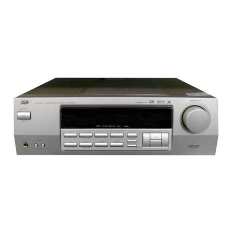
  9. JVC COMPU LINK RX-305TN User manual

JVC COMPU LINK RX-305TN User manual

This manual suits for next models

3

Other JVC Receiver manuals

JVC RX-6500VBK - Dolby Digital/DTS Audio/Video... User manual

JVC

JVC RX-6500VBK - Dolby Digital/DTS Audio/Video... User manual

JVC RX-5022VSL User manual

JVC

JVC RX-5022VSL User manual

JVC KD-X220 User manual

JVC

JVC KD-X220 User manual

JVC KD-X382BT User manual

JVC

JVC KD-X382BT User manual

JVC RX-8030VBK User manual

JVC

JVC RX-8030VBK User manual

JVC RX-7520VBK User manual

JVC

JVC RX-7520VBK User manual

JVC RX-8040B User manual

JVC

JVC RX-8040B User manual

JVC RX-7042S User manual

JVC

JVC RX-7042S User manual

JVC RX-5022RSL User manual

JVC

JVC RX-5022RSL User manual

JVC KD-AV7005 User manual

JVC

JVC KD-AV7005 User manual

JVC RXD702B - AV Receiver User manual

JVC

JVC RXD702B - AV Receiver User manual

JVC UX-LP5B, UX-LP5E, UX-LP5EN User manual

JVC

JVC UX-LP5B, UX-LP5E, UX-LP5EN User manual

JVC RX-6000VBK User manual

JVC

JVC RX-6000VBK User manual

JVC KD-DV4402 User manual

JVC

JVC KD-DV4402 User manual

JVC RX-5062S User manual

JVC

JVC RX-5062S User manual

JVC KD-AVX20E User manual

JVC

JVC KD-AVX20E User manual

JVC RX-7000RBK User manual

JVC

JVC RX-7000RBK User manual

JVC RXD212B - 110 Watts X 7 Receiver User manual

JVC

JVC RXD212B - 110 Watts X 7 Receiver User manual

JVC EXAD KW-AVX820 User manual

JVC

JVC EXAD KW-AVX820 User manual

JVC KD-NXD505J User manual

JVC

JVC KD-NXD505J User manual

JVC KD-G821 User manual

JVC

JVC KD-G821 User manual

JVC RX-668VBK User manual

JVC

JVC RX-668VBK User manual

JVC RX-668RBK User manual

JVC

JVC RX-668RBK User manual

JVC KW-V640BT User manual

JVC

JVC KW-V640BT User manual

Popular Receiver manuals by other brands

Televes ZAS HD SAT user manual

Televes

Televes ZAS HD SAT user manual

Realistic DX-75 Operating and service instructions

Realistic

Realistic DX-75 Operating and service instructions

Saris 4620 Assembly instructions

Saris

Saris 4620 Assembly instructions

Mini DTR 206C PVR user manual

Mini

Mini DTR 206C PVR user manual

RF Elements TwistPort manual

RF Elements

RF Elements TwistPort manual

Denon DN-200WS user guide

Denon

Denon DN-200WS user guide

Yamaha RX-V467 owner's manual

Yamaha

Yamaha RX-V467 owner's manual

Russound SaphIR 858 instruction manual

Russound

Russound SaphIR 858 instruction manual

Quasonix RDMS Firmware update procedure

Quasonix

Quasonix RDMS Firmware update procedure

Pioneer XV-HTD1 Service manual

Pioneer

Pioneer XV-HTD1 Service manual

ATZ HDMI-V2-44HE150 manual

ATZ

ATZ HDMI-V2-44HE150 manual

Sony XNV-770BT MyTomTom Specifications

Sony

Sony XNV-770BT MyTomTom Specifications

Grundig STR 7122 TWIN Service manual

Grundig

Grundig STR 7122 TWIN Service manual

Creative Blaster Modem user guide

Creative

Creative Blaster Modem user guide

Panduit ATLONA AT-OME-RX11 installation guide

Panduit

Panduit ATLONA AT-OME-RX11 installation guide

VOLTCRAFT UTPS-40 operating instructions

VOLTCRAFT

VOLTCRAFT UTPS-40 operating instructions

Litelink VT-1001 operating instructions

Litelink

Litelink VT-1001 operating instructions

Sangean WR-11 Service manual

Sangean

Sangean WR-11 Service manual

manuals.online logo
manuals.online logoBrands
  • About & Mission
  • Contact us
  • Privacy Policy
  • Terms and Conditions

Copyright 2025 Manuals.Online. All Rights Reserved.

INSTRUCTIONS
RX-305TN/3S05LTN
RX-304BK/S304LBK
COMPUTER
CONTROLLED
RECEIVER
BEDIENUNGSANLEITUNG:
COMPUTERGESTEUERTER
RECEIVER
INSTRUCTIONS:
AMPLI-SYNTONISEUR
COMMANDE
PAR
ORDINATEUR
GEBRUIKSAANWIJZING:
KOMPUTER
GESTUURFDE
RECEIVER
INSTRUCCIONES:
RECEPTOR
CONTROLADO
POR
COMPUTADORA
BRUKSANVISNING:
ATORSTYRD
RECEIVER
COMPULING
=
il'Remeoie
|iil
Control
Component
For
Customer
Use:
Enter
below
the
Model
Ny.
and
Serial
Nc
which
is
located
either
ortme
rear,
bottor
or
side
of
the
cabinet.
Réa
gn
this
infor
mé
tion
for
future
reference
Model
No.
Serial
No.
4
§
E
3
i
|
E30580-1
66
|
;
:
IMPORTANT
(in
the
United
Kingdom)
Mains
Supply
(AC
240
V’v,
50
Hz
only)
IMPORTANT
Do
not
make
any
connection
to
the
Larger
Terminal
coded
E
or
Green.
The
wires
in
the
mains
fead
are
coloured
in
accordance
with
the
following
code:
Blue
to
N
(Neutral)
or
Black
Brown
to
L
(Live)
or
Red
If
these
colours
do
not
correspond
with
the
terminal
identifi-
cations
of
your
plug,
connect
as
follows:
Blue
wire
to
terminal
coded
N
(Neutral)
or
coloured
Black.
Brown
wire
to
terminal
coded
L
(Live)
or
coloured
Red.
/f
in
doubt
—
consult
a
competent
electrician.
IMPORTANT
FOR
AC
OUTLET(S)
Connect
only
the
audio
equipments.
Moreover
do
not
connect
any
equipments
which
have
a
power
con-
sumption
exceeding
the
value
indicated
by
the
AC
OUTLET(S).
BEMAERK:
|
stilling
OFF
er
apparatet
stadig
forbundet
med
lysnettet.
Hvis
det
@nskes
fuldstaendig
afbrudt
skal
netledningen
traekkes
ud.
VARNING
Strémstallaren
POWER
ar
sekundart
kopplad
och
skiljer
inte
apparaten
fran
natet
i
lage
STAND
BY.
For
att
apparaten
skall
skiljas
fran
natet
skall
natsladden
dras
ur
fran
vaggutta-
get.
IMPORTANT
(CANADA
ONLY/CANADA
SEULEMENT)
CAUTION:
TO
PREVENT
ELECTRIC
SHOCK
DO
NOT
USE
THIS
(POLARIZED)
PLUG
WITH
AN
EXTENSION
CORD,
RECEPTACLE
OR
OTHER
OUTLET
UNLESS
THE
BLADES
CAN
BE
FULLY
INSERTED
TO
PREVENT
BLADE
EXPOSURE
ATTENTION:
POUR
PREVENIR
LES
CHOCS
ELECTRIQUES
NE
PAS
UTILISER
CETTE
FICHE
POLARISEE
AVEC
UN
PROLONGATEUR,
UNE
PRISE
DE
COURANT
OU
UNE
AUTRE
SORTIE
DE
COURANT,
SAUF
SI
LES
LAMES
PEUVENT
ETRE
INSEREES
A
FOND
SANS
EN
LAISSER
AUCUNE
PARTIE
A
DECOUVERT
eas
|
COMPU
LINK
IiiiRemote
/Iil
Control
System
COMPU
LINK
is
a
computer-linked
system
in
which
microcomputers
in
individual
JVC
audio
and/or
video
components
control
the
system's
operation.
For
details,
see
page
15.
COMPU
LINK
ist
eine
Computer-gesteverte
Verkopplung
einzelnerJVC
Audio-
und
Video-
komponenten,
Weitere
Angaben
hierzu
siehe
Seite
27.
COMPU
LINK
est
un
systéme
de
liaison
a
ordinateur
dans
lequel
des
microprocesseurs
dans
des
appareils
audio
et/ou
vidéo
JVC
indépendants
commandent
Je
fonctionnement
du
systéme.
Pour
de
détails,
voir
en
page
39.
ene
ee
COMPU
LINK
is
een
komputer
testuurd
sys-
teem
waarbij
mikrokomputers
in
de
afzonder-
lijke
JVC
audio
en/of
video
komponenten
de
bediening
van
het
systeemn
regelen.
Zie
biz.
51
voor
details.
COMPU
LINK
es
un
sistema
de
enlace
por
computadora
en
el
cual
tas
microcomputadoras
en
los
componentes
de
audio
y/o
video
de
JVC
controlan
el
functionamiento
del
sistema.
Para
mayores
detalles,
refigrase
a
la
pagina
63.
COMPU.
LINK
4
ett
datorlankat
system
i
vilket
mikrodatorer:
i
varje
enskild
tjud-
och/
eller
videokomponent
av
fabrikatet
JVC
styr
anlaggningen.
Se
naérmare
beskrivning
pa
sidan
75,
CAUTION
To
reduce
the
risk
of
electrical
shocks,
fire,
etc.:
1.
Do
not
remove
screws,
covers
or
cabinet.
2.
Do
not
expose
this
appliance
to
rain
or
moisture.
SS
Thank
you
for
purchasing
this
JVC
product.
Before
you
begin
operating
this
unit,
please
read
the
instructions
carefully
to
be
sure
you
get
the
*best
possible
performance.
If
you
have
any
questions,
consult
your
JVC
dealer.
Note:
®
This
instruction
manual
has
been
prepared
for
the
four
models,
the
model
numbers
of
which
are
shown
on
the
front
cover.
Model
numbers
with
an
L
suffix
show
receivers
which
can
receives
LW
broadcasts.
VOORZICHTIG
Ter
vermindering
van
gevaar
voor
brand,
elek-
trische
schokken,
enz.:
1.
Verwilder
geen
schroeven,
panelen
of
de
be-
huizing.
2.
Stel
dit
toestel
niet
bloot
aan
regen
of
vocht.
Dank
U
voor
het
in
dit
JVC
produkt
gestelde
ver-
trouwen.
Lees
deze
gebruiksaanwijzing
vodér
ingebruikname
van
dit
loestet
aandachtig
door
ter
verkrijging
van
de
beste
prestaties.
Raadpleeg
Uw
JVC
dealer
in
geval
van
twijfel.
Opmarking:
®@
De
toepassing;
de
modeinummers
hiervan
zijn
op
de
voorkant
van
de
omslag
aangeven.
Modelnummers,
eindipend
op
een
L,
duiden
op
tuner-versterker,
waannee
ultzendingen
op
de
lange
golf
kunnen
warden
ontvangen.
ACHTUNG
Zur
Verhinderung
von
elektrischen
Schlagen,
Brandgefahr
usw.:
1.
Keine
Schrauben
l6sen
oder
Abdeckungen
ent-
fernen
und
nicht
das
Gehause
Offnen.
2.
Dieses
Gerat
weder
Regen
noch
Feuchtigkeit
aussetzen.
Vielen
Dank
fur
den
Kauf
dieses
JVC-Produkts.
Bitte
lesen
Sie
diese
Bedienungsanleitung
sorg-
faltig,
bevor
Sie
dieses
Gerat
in
Betrieb
nebmen,
um
die
beste
Leistung
zu
erhalten.
Falls
Sie
Fragen
haben,
wenden
Sie
sich
bitte
an
thren
JVC-Fachhandier.
Hinweis:
®
Diese
Bedienungsanleitung
ist
fir
die
vier
Modelle
vorgesehen,
deren
Modellbezeichnung
auf der
Vorderseite
abge
druckt
ist.
Die
L-
Bazeichnung
kannzeichnet
fir
LW
Empfang
geeigneta
Gerate.
PRECAUCION
Para
reducir
riesgos
de
electrochoques,
incendio,
etc.:
1.
No
extraiga
los
tornillos,
cubiertas
o
la
caja.
2.
No
exponga
este
aparato
a
la
lluvia
o
humedad.
SS
Deseamos,
antes
que
nada,
agradecerle
por
la
compra
de
unos
de
los
productos
de
JVC.
Antes
de
poner
esta
unidad
en
operacién
asegu-
rese
de
leer
estas
instrucciones
para
de
tal
modo,
obtener
el
mayor
rendimiento
posible.
Cualquier
duda
o
pregunta,
sirvase
dirigirse
a
su
concesionario
JVC.
Nota:
@
Este
manual
de
instrucciones
ha
sido
prepa-
rado
para
los
cuatro
modelos
cuyos
numeros
figuran
en
la
tapa
delantera.
Los
que
llevant
una
L
como
sufijo
indican
que
pueden
captar
transmisiones
en
OL
(LW).
ATTENTION
Afin
d’éviter
tout
risque
d’électrocution,
d‘incen-
die
etc.:
1.
Ne
pas
enlever
les
vis
ni
les
panneaux
et
ne
pas
ouvir
le
coffret
de
|’appareil.
2.
Ne
pas
exposer
l'appareil
a
la
pluie
ni
a
I’hu-
midité.
—————_—
Nous
vous
remercions
pour
|’achat
de
cet
appa-
reil
de
JVC.
Pour
que
vous
puissiez
obtenir
les
meilleures
per-
formances
possibles,
nous
vous
recommandons
de
lire
attentivement
la
présente
notice
d'emploi
avant
de
commencer
a
utliser
votre
nouvel
app-
lareil.
En
cas
de
question,
consultez
votre
revendeur
JVC.
Remarque:
®
Ce
manuel
d’instructions
est
destiné
aux
quatre
modéles
dont
le
numéro
est
inscrit
en
page
de
couverture.
Les
numéros
de
modé-
les
accompagnés
du
suffixe
L
indiquent
que
les
ampli-syntoniseurs
peuvant
recevoir
les
émissions
GO.
VARNING
Elektriska
stétar
och
Overslag
i
apparaten
kan
elimineras
genom
fdljande:
1.
Ta
inte
bort
struvar,
lock
eller
ytterhdlje
fran
apparaten.
2.
Utsatt
inte
apparaten
fdr
regn
eller
fukt.
i
aaa
Tack
fér
valet
av
denna
JVC-produkt.
Las
noga
igenom
dessa
anvisningar
innan
apparaten
bér-
jar
anvandas
fér
att
erhalla
basta
mojliga
ijudater-
givning.
FOr
ytterligare
information,
kontakta
JVC-handlaren.
Anm:
@
Denna
bruksanvisning
beskriverfyra
modeller;
modellnumren
anges
p&
omslaget.
De
bada
modellemas
handhavande
ar
traktiskt
taget
klentiska.
CONTENTS
Important
Notes
.............
ccc
cece
e
eee
eee
renee
Connection
Diagram
...
Antennas
..............065
Front
panel
..............
Basic
Operation
...............0cccceeeee
eee
Listening
to
AM
or
FM
Broadcasts
Playing
Back
Sources
(PHONO,
CD,
TAPE1,
TAPE2/VIDEO
SOUND)
.............
11
RECOPING,
(iscs
sini
scctitlontheselnt
totes
Korein
de
Ss
12
Operation
with
the
Remote
Control
Unit
......
13
Inserting
Batteries
in
the
Remote
Control
ON
cee
cas
cevew
sewer
ts
tonne
seve
eset:
15
COMPU
LINK
Remote
Control
System
........
15
Troubleshooting
wee
16
Specifications
0.26.2...
eects
77
BOlEN
GFK:
osccces
vs
ieitinnsac
cde
be
obi
sbatnd
nonewecucees
3
AansluitSchema
...........00.cceeceeee
eee
vee
41
Antennes
..............
we
42
Voorpaneel
............0..c00
we
43
BOdiON
ING
»..cicceververy
eddie
wwcene
dmesvieeede?
we
44
Luisteren
naar
de
AM
of
FM
radio
.............
45
Weergave
van
geluidsbronnen
(PHONO,
CD,
TAPE
1,
TAPE
2/VIDEO
SOUND)
............
47
Maken
van
bandopnamen
.............6....0008
48
Bediening
van
de
tuner/versterker
op
afstand
49
Batterij-inleg
voor
de
afstandsbediening
.......
51
COMPU
LINK
afstandsbedieningssysteem
....
51
Zelf
storingen
verhelpen
..............ceceeeneee
52
Technische
gegevens
...............:seeeeeeeee
ees
80
INHALT
Wie
tig
tse
toot
elected
Utils
te
3
Schaltbild
....
Bere
A
Antennen
....
...
18
Frontplatte
...............0.06
we
19
Grundiegende
Bedienung
.....................:565
20
H6éren
von
MW/LW-
order
UKW-Sendungen
21
Wiedergabe
von
Tonquellen
(PHONO,
CD,
TAPE
1,
TAPE
2/VIDEO
SOUND)
AUTNANIMG
ios
eeea
cases
Saved
abuse
sev
aientee
se
Betrieb
mit
Fernbedienugsteil
....................
Einlegen
der
Batterien
in
das
Fernbedienungsteil
27
COMPU
LINK
Fernbedienung
2
Fehlersuche
................0:.25005
oe
Technische
Daten
...............c0cceeeeeee
eee
eee
INDICE
Notas
importantes
........0.......c
cece
sence
rece
e
es
3
Diagrama
de
conexién
PINCTES
seals
eicgss
ces
panto
eeetrs
Panel
frontal
.............
Operacién
basica
Escucha
de
programas
radiofénicos
de
AMO
FM
sic
ccesenduce
ea
segs
Sergceoendaneecs
57
Reproduccién
de
fuentes
(PHONO,
CD,
TAPE
1,
TAPE
2/VIDEO
SOUND)
...........
59
GPADACION
“ec
crdsida.cacserdinse
teaudborielazanetscases
60
Operacién
con
la
unidad
de
contro!
remote
.
61
Insercién
de
las
pilas
en
la
unidad
de
CONTO!
TEMOTO.
«cesses
ctinceceeewetcs
sist
eceees
63
Sistema
de
contro!
remoto
COMPU
LINK
....
63
Soluci6n
de
problemas
.................:.ceeeee
64
EspecificacioneS
...............csceeeeeeeeeeeeee
eens
81
SOMMAIRE
Remarques
importantes
.............:.seeeeeeeee
ees
Schéma
des
connexions
...
Antennes
...............00e
eee
Panneau
avant
.............055
as
Fonctionnement
de
base
............:scereeeeees
Ecoute
d’émissions
en
AM
ou
en
FM
.........
33
Lecture
de
sources
sonores
(PHONO,
CD,
TAPE
1,
TAPE
2/VIDEO
SOUND)
...........
35
Enregistrement
..............0ecce
eee
eee eee
ee
nee
es
36
Fonctionnement
avec
la
télecommande
.......
37
Insertion
des
piles
dans
la
télécommande
....
39
Systeme
de
commande
4
distance
Compu
Link
39
Dépannage
|
ss.dis
dea
vaaysesskecss
tiated
eeiiees
40
Caracteéristiques
.........
0...
ecece
cee
e
cena
eee
ee
eens
79
INNEHALL
Viktiga
anmarkningar
Kopplingsdiagram
..........
ANtennerma
.........
eee
eee
eect
eens
Reglage
pa
framsidan
Grundlaggande
tillvagagangsatt
AM-
eller
FM-
mottagning
.......-.:0e:eseereeee
Ljudatergivning
fran
anslutna
komponenter
(PHONO,
CD,
TAPE
1,
TAPE
2/
VIDEO:;SOUND)
on.
cc2s
nwo
ee
eenctaad cosmwens
teas
INSPAINING
20.0...
eee
eee
e
eee
eee
es
Fjarrstyrning
med
fjarrkontroll
Batteriernas
isattning
i
fjarrkontrollen
...........
75
Fjarrstyrningslanken
COMPU
LINK
.............
75
FelSOKNING:
Satacvircsitins
ea
eae
eae
76
Tekniska
data
..............cceeee
cette
cence
renee
ens
82
IMPORTANT
NOTES
1.
Installation
@
Select
a
place
which
is
leve,
dry
and
neither
too
hot
nor
too
cold
(between
—5°C
and
40°C/23°F
and
104°F).
@
Be
sure
there
is
adequate
ventilation;
poor
ven-
tilation
may
cause
the
unit
to
malfunction.
®
Leave
sufficient
distance
between
the
receiver
and
your
TV.
2.
Power
®@
Do
not
handle
the
power
cord
with
wet
hands!
@
When
unplugging
from
the
wall
outlet,
always
pull
the
plug,
not
the
power
cord.
3.
Malfunctions
etc.
@
Do
not
insert
any
metalic
objects
into
the
receiver.
BELANGRUK
1.
Installeren
@
Zoek
een
plaats
uit
die
waterpas,
droog
en
noch
te
warm,
noch
te
koud
is
(tussen
—
5°C
en
40°C).
@
Zorg
dat
er
genoeg
ventilatie
is:
slechte
ven-
tilatie
kan
er
de
oorzaak
van
zijn
dat
het
toestel
niet
good
werkt.
®
Houd
het
toestel
zover
mogelijk
van
de
TV
ver-
wijderd.
.
Netsnoar
Raak
het
netsnoor
noolt
met
natte
handen
aan!
Neem
altijd
de
stekker
zelf,
nooit
het
snoer,
beet
wanneer
de
stekker
uit
het
stopkontakt
getrokken
wordt.
.
Defekten,
enz.
Steek
geen
metalen
voorwerp
in
de
tuner.
een
eW
WICHTIG
_
.
Autstellung
®@
Das
Gerat
auf
eine
ebene
Flache
stellen.
Der
Aufstellungsort
sollte
trocken
und
weder
zu
warm
noch
2u
kait
sein
(zwischen
—5°C
und
+40°C).
@
Ausreichende
Beluftung
gewahrieisten.
Unzu-
relchende
Beltiftung
kann
Stérungen
verur-
sachen.
@
Zwischen
dem
Receiver
und
dem
Fernseher
ei-
nen
ausreichenden
Abstand
einhalten.
2.
Netzkabel
®@
Das
Netzkabel
nicht
mit
feuchten
Handen
an-
fassen.
@
Zum
Abtrennen
des
Netzkabels
von
der
Steck-
dose
immer
am
Stecker
ziehen,
niemails
am
Kabel.
3.
Fehlfunktionen
usw.
®@
Darauf
achten,
da
keine
Metallgegenstande
in
den
Receiver
eindringen.
NOTAS
IMPORTANTES
=
.
Instalaci6n
@
Elija
un
lugar
nivelado,
seco
y
que
no
sea
de-
masiado
caluroso
ni
demasiado
frio
(entre
—5°C
y
+40°C).
@
Tenga
en
cuenta
que
haya
una
ventilacién
ade-
cuada;
la
falta
de
ventilaci6n
puede
ocasionar
fallas
en
la
unidad.
®@
Deje
suficiente
espacio
entre
el
receptor
y
el
televisor.
.
Alimentacién
jNo
toque
el
cordén
de
alimenacién
con
las
manos
mojadas!
®@
Cuando
lo
desenchufe
del
tomacorriente
de
pa-
red,
tire
siempre
de
la
clavija,
no
del
cord6én.
.
Fallas
de
funcionamiento,
etc.
No
inserte
ningun
objeto
metélico
en
el
re-
ceptor.
eh
ew
a3:
REMARQUES
IMPORTANTES
1.
Installation
@
Choisir
un
endroit
plan,
sec
et
ni
trop
chaud,
ni
trop
froid
(entre
—5°C
et
40°C).
@
S’assurer
qu'il
y
a
une
bonne
ventilation;
une
mauvaise
ventilation
peut
causer
un
mauvais
fonctionnement
de
|’appareil.
®
Laisser
une
distance
suffisante
entre
‘amplisyntoniseur
et
votre
téléviseur.
.
Alimentation
Ne
pas
toucher
au
cordon
d’alimentation
avec
les
mains
humides!
@
En
débranchant
|’appareil
de
la
prise
murale,
toujours
tirer
sur
la
fiche,
pas
sur
le
cordon
d’alimentation.
.
Mauvais
fonctionnements,
etc.
Ne
pas
introduite
d’objets
métalliques
dans
l’'ampli-syntoniseur.
VIKTIGA
ANMARKNINGAR
1.
Installation
@
V4Alj
ett
statle
som
ar
plant,
torrt
och
varken
fér
varmt
eller
far
kalti
(mellan
—5
och
40
grader).
®
Se
till
att
god
luftcirculation
finns,
eftersom
da-
lig
ventilation
kan
orsaka
funktio
nsfel.
©
Lamna
tillrackligt
stort
avstand
mel!an
receivern
och
TV-mottagaren.
2.
Natsladd
@
Ta
inte
i
natsladden
med
vata
hander!
©
Hail
afitid
i
stickkontakten,
inte
i
sladden,
nar
sladden
skalf
dras
ur
fran
vaggu
ttaget.
3.
Eventuella
funktionsfel
@
Stoppa
inte
in
metallféremal
i
apparaen.
en
ew
ENGLISH
DEUTSCH
FRANCAIS
NEDERLANDS
ESPANOL
SVENSKA
Connection
Diagram
Switch
the
power
off
when
connecting
any
cables.
Turntable
the
cord.
Cassette
deck
CD
player
Open
the
speaker
terminal
by
pressing
the
lever
and
insert
the
stripped
end
of
Speakers
1
Clamp
the
wire
by
resetting
the
lever.
Speakers
2
ac
ounuet
SWITCHED
SWITCHED
SWITCHED
For
contriental
For
the
U.K.
Video
component
(AUDIO
signal),
cassette
deck
or
S.E.A.
graphic
equalizer.
@
ANTENNA
terminals
@
GND
@©
PHONO,
CD,
TAPE
1,
TAPE
2/VIDEO
SOUND
terminals.
@
COMPU
LINK-1/SYNCHRO
terminals
Connect
to
JVC
components
provided
with
COMPU
LINK-1/
SYNCHRO
terminals
for
the
COMPU
LINK
control
system
function.
@
AC
OUTLETS
(SWITCHED)
@
SPEAKERS
1,
2
terminals
@
AM
channel
spacing
switch**
See
‘‘Listening
to
AM
or
FM
Broadcasts’’
section.
©
Fuse
holder*
@
Voltage
selector**
@
Power
cord
*
Not
provided
on
units
for
Canada,
the
United
Kingdom
and
Aus-
tralia.
**
Not
provided
on
units
for
Canada,
Continental
Europe,
the
Unit-
ed
Kingdom
and
Australia.
Notes:
@
When
connecting
components,
connect
their
left
and
right
chan-
nels
correctly.
If
channels
are
reversed,
the
stereo
effect
will
be
degraded.
®
Connect
speakers
with
the
correct
polarity:
(+)
to
(+)
and(—)
to
(—).
Reversed
polarity
will
degrade
the
stereo
effect.
Be
care-
ful
to
prevent
adjacent
speaker
wires
from
touching
each
other.
@
Use
speakers
with
the
correct
impedance.
The
correct
impedance
is
indicated
on
the
rear
panel
of
the
RX-305TNI(LTN)/
RX-304BK(LBK).
@
The
AC
OUTLETS
do
not
supply
power
when
the
power
switch
is
turned
off.
Do
not
connect
equipment
requiring
more
than
the
outlet’s
rated
value.
@
Do
not
connect
the
remote
cable
when
connecting
the
JVC
cas-
sette
deck
having
COMPU
LINK-1/SYNCHRO
terminals
to
the
TAPE
2/VIDEO
SOUND
terminals.
@
Connect
a
turntables
using
a
moving
magnetic
(MM)
type
car-
tridges
to
the
PHONO
terminals.
For
Australia
For
Canada
ar
Europe
other
areas
ant
enna
TaIS2
007
cin
Qs
AM
antennas
Figure
1:
How
to
assemble
the
AM
loop
antenna
Figure
2:
AM
loop
antenna
This
antenna
is
for
the
reception
of
local
AM
broadcasts.
Figure
2:
AM
external
antenna
if
AM
reception
is
unsatisfactory,
connect
an
external
AM
antenna
(single-
wire
antenna)
to
the
AM
EXT
terminal.
Figure
3:
Connection
of
AM
antenna
@
Open
antenna
terminals
levers.
@
Plug
cords
into
the
terminals.
@)
Close
the
levers.
Figure
4:
Noise
and
interference
Change
the
direction
of
the
loop
antenna,
or
re-install
it
in
a
better
position
if
the
reception
is
noisy.
Notes:
@
|f
the
provided
loop
antenna
is
not
connected
or
an
uninsulated
antenna
wire
touches
the
rear
panel,
it
will
be
impossible
to
receive
AM
broadcasts.
®@
When
installing
an
external
AM
antenna,
leave
the
AM
loop
antenna
connected.
FM
antennas
@:
Except
for
Continental
Europe
Figure
5:
75-ohm
antenna
with
coaxial
Loosen
the
screws
on
the
bracket
and
insert
the
cable
through
the
ring
from
below.
Connect
the
stripped
core
to
the
upper
terminal
then
tighten
the
ring.
The
ring
is
the
antenna
ground.
Figure
6:
Feeder
antenna
Connect
to
the
FM
300
©
terminals.
Make
sure
the
feeder
antenna
wires
do
not
touch
any
other
terminals.
®):
For
F.R.
Germany
Figure
7:
75-ohm
antenna
with
coaxial
@
The
FM
wire
antenna
provided
can
be
connected
to
a
FM
75
Q
COAXIAL
terminal
as
a
temporary
measure.
®@
A
75-ohm
antenna
with
coaxial
type
connector
(DIN
45
332)
should
be
connected
to
the
FM
75
2
COAXIAL
terminal.
©:
For
Continental
Europe
Figure
8:
75-ohm
antenna
with
coaxial
1.
Open
the
claws
at
both
sides
and
remove
the
cover.
2.
Cut
both
ends
of
the
cord
and
remove
it.
3.
Fix
the
coaxial
cable
and
its
core.
4.
Put
on
the
cover.
Figure
9:
300-ohm
antenna
Attach
the
feeder
antenna
to
the
FM
connector
as
shown
in
the
figure.
Connect
the
FM
connector
to
the
FM
75
Q
COAXIAL
terminal.
|
Antenna
Connections
AM
external
antenna
FM
feeder
antenna
®
FM
75-ohm
antenna
AM
liop
antenna
®©O
For
Continental
Europe
and
F.R.
Germany
—6—
RX-305TN(LTN)/RX-304BK(LBK)
@
POWER
(ON/STANDBY)
Press
this
button
to
turn
the
power
ON.
Press
again
to
turn
the
power
off
and
activate
the
STANDBY
mode.
The
STANDBY
in-
dicator
will
light.
A
small
amount
of
power
(5
watts)
is
consumed
in
the
STAND-
BY
mode.
To
turn
the
power
off
completely,
disconnect
the
power
cord
from
the
wall
outlet.
Preset
data
is
retained
in
memory
while
the
power
cord
is
plugged
into
the
wall
outlet.
If
the
power
cord
is
disconnected
or
a
power
failure
occurs,
data
is
retained
for
two
or
three
days.
©
SPEAKERS
1,
2
Turns
speakers
1
and
2
ON
or
OFF.
©
PHONES
Plug
headphones
into
this
jack.
If
you
want
to
hear
from
the
head-
phones
alone,
turn
OFF
speakers
1
and
2.
©
TREBLE
Ajusts
treble
sound.
Slide
the
knob
to
the
left
to
weaken
the
tre-
ble
sound
and
to
the
right
to
strengthen
it.
@
BASS
Adjusts
bass
sound.
Slide
the
knob
to
the
left
to
weaken
the
bass
sound
and
to
the
right
to
strengthen
it.
@
SURROUND
Turns
the
surrund
sound
effect
ON
or
OFF.
@
LOUDNESS
Turns
LOUDNESS
ON
or
OFF.
The
ON
position
makes
up
for
loss
of
the
human
auditory
sensation
when
the
sound
volume
is
low.
©
SOURCE
Use
the
following
keys
to
select
sources:
PHONO:
Press
to
listen
to
records.
CD:
Press
to
listen
to
CDs.
FM:
Press
to
listen
to
FM
broadcasts.
Press
to
listen
to
AM
(MW/LW)
broadcasts.
Press
to
operate
the
tape
deck
connected
to
the
TAPE
1
terminals.
TAPE
2/VIDEO
SOUND:
Press
to
operate
the
tape
deck
or
video
equipment
connected
to
the
TAPE
2/VIDEO
SOUND
terminalis.
(alternates
between
ON
and
OFF)
AM
(MW/LW):
TAPE
1:
@
BALANCE
L,
R
Adjusts
the
volume
balance
between
the
left
and
right
speakers.
@
TUNER
Use
the
following
keys
to
listen
to
AM
or
FM
broadcasts:
MEMORY:
Stores
an
AM
or
FM
frequency
(station)
on
a
preset
channel.
Stores
an
AM
or
FM
frequency
on
a
preset
channel
using
the
AUTO
MEMORY
feature.
FM
MODE/MUTE:
Selects
FM
reception
modes.
TUNING
<,>:
Tunes
in
an
AM
or
FM
frequency.
1-10,
+10
(Tuner
numeric
keys):
Press
to
select
preset
channels.
AUTO
MEMORY:
@
MUTE
Turns
sound
ON
or
OFF
temporarily.
@
VOLUME
<,>
Adjusts
the
volume
of
sound
from
the
speakers
or
headphones.
@®
REMOTE
SENSOR
Receives
signals
from
the
remote
control
unit.
©
RECEIVED
and
POWER
STANDBY
indicator
Lights
when
signals
are
received
from
the
remote
control
unit
or
when
the
machine
is
in
the
STANDBY
mode.
©
Display
and
indicator
Shows
the
operating
status.
—
Before
Operating
—
Before
plugging
the
power
cord
into
an
AC
outlet,
check
to
be
sure
the
individual
components
are
connected
correctly.
4
1.
Turn
the
POWER
switch
to
ON.
POWER
ON/STANDBY
Note:
lf
a
malfunction
occurs
when
the
power
is
ON,
unplug
the
power
cord
and
then
plug
it
in
again.
2.
Select
aspeaker
system
by
pressing
one
of
the
SPEAKERS
keys.
1
SPEAKERS
2
ON,
OFF
Note:
x
If
speakers
are
not
connected
to
both
SPEAKERS
1
and
2
terminals,
do
not
turn
ON
both
speaker
systems
as
that
would
suppress
sound
output.
3.
Operate
these
keys,
as
needed,
by
following
the
directions
given
further
on.
oo
co ew an
TAPES
<
ua
>
WoO
4.
Adjust
the
VOLUME
and
BALANCE
keys
to
your
taste.
"10
VOLUME
°5
ny
<
VOUME
>
io
tL
BALANCE
R
Note:
These
keys
vary
their
settings
while
they
are
being
pressed.
_
BALANCE
Ls
|
5.
Adjust
the
TREBLE
and
BASS
knobs
for
desired
sound.
6.Press
the
LOUDNESS
and
MUTE
keys
as
needed.
®
Press
to
make
up
for
loss
of
the
human
auditory
sensation
when
the
sound
volume
is
low.
LOUDNESS
LOUDNESS
®@
Press
to
temporarily
cancel
sound
output.
Mt)
7
Co
Pro)
fF
7b
MUTE
Note:
The
MUTE
key
is
reset
when
the
VOLUME
or
BALAN'E
keys
are
pressed.
Listening
to
AM
or
FM
Broadcasts
=
Selecting
a
Station
1.Press
the
AM
(MW/LW)
or
FM
key.
FM
AM
2.
Use
the
TUNING
keys
to
find
a
station.
<<
TUNING
>
N
Hold
the
TUNING
key
down
to
change
the
frequency
faster,
then
tap
the
key
to
set
the
frequency
precisely.
In
the
RX-305LTN/
RX-304LBK
when
tuning
reaches
the
upper
limit
of
the
LW
frequencies,
it
automatically
skips
to
the
lower
limit
of
the
MW
fre-
quencies.
The
opposite
may
also
occur.
CIT
CUT
oe
AW”
Auto-tuning
starts
when
the
TUNING
keys
are
released
and
stops
when
a
station
is
tuned.
To
halt
auto-tuning,
press
a
TUNING
key.
A
three-digit
number
is
used
to
display
an
FM
frequency
for
equip-
ment
exported
to
Canada.
3.
The
TUNED
indicator
will
light
when
a
station
is
tuned
in
correctly.
[TONED]
[STERES]
MUTE
Of
Mens
ace
a
ven
Adjust
the
antenna
if
the
indicator
does
not
light.
@
While
tuning
in
an
FM
station,
press
the
FM
MODE/MUTE
key
to
light
the
MUTE/AUTO
indicator,
this
cuts
out
inter
station
noise
while
tuning.
@
The
STEREO
indicator
will
tight
when
an
FM
stereo
station
is
tuned
in
correctly.
If
the
FM
stereo
station
is
weak
and
noisy,
press
the
FM
MODE/MUTE
key
again
to
turn
off
the
MUTE/AUTO
indicator
to
improve
reception
(broadcast
becomes
monaural).
=
Presetting
Stations
You
can
preset
a
total
of
40
AM
(MW/LW)
and
FM
station
(CH
1
through
CH
40).
1.
Tune
in
the
desired
station
with
the
TUNING
keys.
MUTE
sTereo]
MUTE
Pia
ED
A)
we
_I
f.
ILI
2.
Press
the
MEMORY
key
to
light
its
indicator.
revony
wre
mis
mic}
FM
LL
L
Mize
P\
a
ee
ge
|
ch
3.
Enter
the
channel
number
with
numeric
keys
while
the
indicator
is
on
(for
about
5
seconds).
at)
oe]
(STERES]
TE
rm
CI
ILE)
¥
bs
ne
aa
a
@
If
the
indicator
turns
off
before
you
enter
the
channel
number,
press
the
MEMORY
key
again.
4.
Repeat
this
procedure
to
preset
other
channels.
®
Recalling
preset
channels
1.
Press
numeric
keys
to
select
a
preset
channel.
’
2
(Fonen]
(STeRES)
ATS
CH-
[3S
mG
lS0e
be
®
To
indicate
numbers
1
through
10,
simply
press
the
appropriate
keys.
To
indicate
numbers
over
10,
press
the
appropriate
combination
of
keys.
Examples;
To
indicate
17,
press
‘+10’,
then
‘’7"'.
To
indicate
20,
press
‘'+
10",
then
‘‘10’’.
To
indicate
26,
press
‘'+
10’
twice,
then
‘‘6"’.
To
indicate
40,
press
‘‘+10’’
three
times,
then
‘’10°'.