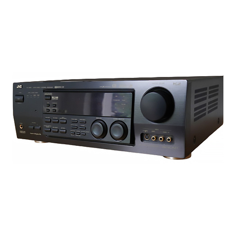
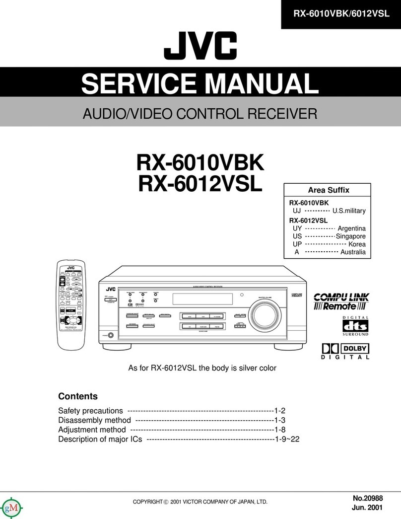
JVC RX-777VBK User manual

RX-777VBK
RX-777VSBK
RX-777VLBK
MODEL
No.
RX-7
f
7VBK
RX-777VSBK
RX-77/7VLBK
No.
20055
May.
1988

RX-777VBK
RX-777VSBK
RX-777VLBK
Warning
ahwnrnd
—
Safety
Precautions
1.
The
design
of
this
product
contains
special
hardware
and
many
circuits
and
components
specially
for
safety
purposes.
For
continued
protection,
no
changes
should
be
made
to
the
original
design
unless
authorized
in
writing
by
the
manufacturer.
Replacement
parts
must
be
identical
to
those
used
in
the
original
circuits.
Service
should
be
per-
formed
by
qualified
personnel
only.
.
Alterations
of
the
design
or
circuitry
of
the
product
should
not
be
made.
Any
design
alterations
of
the
product
should
not
be
made.
Any
design
alterations
or
additions
will
void
the
manufacturer's
warranty
and
will
further
relieve
the
manufacturer
of
responsibility
for
personal
injury
or
property
damage
resulting
therefrom.
.
Many
electrical
and
mechanical
parts
in
the
product
have
special
safety-related
characteristics.
These
characteristics
are
often
not
evident
from
visual
inspection
nor
can
the
protection
afforded
by
them
necessarily
be
obtained
by
using
replacement
components
rated
for
higher
voltage,
wattage,
etc.
Replacement
parts
which
have
these
special
safety
characteristics
are
identified
in
the
Parts
List
of
Service
Manual.
Electrical
components
having
such
features
are
identified
by
shading
on
the
schematics
and
by
(
A\)
on
the
Parts
List
in
the
Service
Manual.
The
use
of
a
sub-
stitute
replacement
which
does
not
have
the
same
safety
characteristics
as
the
recommended
replacement
part
shown
in
the
Parts
List
of
Service
Manual
may
create
shock,
fire,
or
other
hazards.
.
The
leads
in
the
products
are
routed
and
dressed
with
ties,
clamps,
tubings,
barriers
and
the
like
to
be
separated
from
live
parts,
high
temperature
parts,
moving
parts
and/or
sharp
edges
for
the
prevention
of
electric
shock
and
fire
hazard.
When
service
is
required,
the
original
lead
routing
and
dress
should
be
observed,
and
it
should
be
confirmed
that
they
have
been
returned
to
normal,
after
re-assembling.
.
Leakage
current
check
(Electrical
shock
hazard
testing)
After
re-assembling
the
product,
always
perform
an
isolation
check
on
the
exposed
metal
parts
of
the
product
{antenna
terminals,
knobs,
meta!
cabinet,
screw
heads,
headphone
jack,
control
shafts,
etc.)
to
be
sure
the
product
is
safe
to
operate
without
danger
of
electrical
shock.
Do
not
use
a
line
isolation
transformer
during
this
check.
e
Plug
the
AC
line
cord
directly
into
the
AC
outlet.
Using
a
‘Leakage
Current
Tester”,
measure
the
leakage
current
from
each
exposed
metal
part
of
the
cabinet,
particularly
any
exposed
metal
part
having
a
return
path
to
the
chassis,
to
a
known
good
earth
ground.
Any
leakage
current
must
not
exceed
0.5
mA
AC
(r.m.s.).
e
Alternate
check
method
Plug
the
AC
line
cord
directly
into
the
AC
outlet.
Use
an
AC
voltmeter
having
1,000
ohms
per
volt
or
more
sensi-
tivity
in
the
following
manner.
Connect
a
1,500
2
10
W
resistor
paralleled
by
a
0.15
uF
AC-type
capacitor
be-
tween
an
exposed
metal
part
and
a
known
good
earth
ground.
Measure
the
AC
voltage
across
the
resistor
with
the
AC
VOLTMETER
AC
voltmeter.
ae,
(Having
1000
ohms/volt,
:
'
or
more
sensitivity.)
Move
the
resistor
connection
to
each
exposed
metal
part,
particularly
any
exposed
metal
part
having
a
return
path
to
the
chassis,
and
measure
the
AC
volt-
Deh
BRE
AC
TXEE
h
i 5
r
i
age
across
the
resistor.
Now,
reverse
the
plug
in
the
Place
this
probe
AC
outlet
and
repeat
each
measurement.
Any
voltage
|
—-
on
each
exposed
measured
must
not
exceed
0.75
V
AC
(r.m.s.).
This
15002
10W
metal
part.
corresponds
to
0.5
mA
AC
(r.m:.s.).
Goad
cartingiound
.
This
equipment
has
been
designed
and
manufactured
to
meet
international
safety
standards.
.
It
is
the
legal
responsibility
of
the
repairer
to
ensure
that
these
safety
standards
are
maintained.
.
Repairs
must
be
made
in
accordance
with
the
relevant
safety
standards.
.
It
is
essential
that
safety
critical
components
are
replaced
by
approved
parts.
.
If
mains
voltage
selector
is
provided,
check
setting
for
local
voltage.
1-2
(No.
20055)

Instruction
Book
SPECIFICATIONS
AMPLIFIER
SECTION
Output
power:
(CD
IN~>SP.
OUT)
2-channel
operation
4-channel
operation
Front
channel
Rear
channel
Total
harmonic
distortion
Intermodulation
distortion
:
80
watts
per
channel,
min,
RMS,
both
channels
driven
into
8
ohms
from
20
Hz
to
20
kHz,
with
no
more
than
0.007
%
total
harmonic
distortion
80
watts
per
channel,
min,
RMS,
both
channels
driven
into
8
ohms
at
1
kHz,
with
no
more
than
0.003
%**
total
harmonic
distortion
:
75
watts
per
channel,
min,
RMS,
both
channels
driven
into
8
ohms
from
20
Hz
to
20
kHz,
with
no
more
than
0.007
%
total
harmonic
distortion
:
7
watts
per
channel,
min,
RMS,
both
channels
driven
into
8
ohms
at
1
kHz,
with
no
more
than
0.7
%
total
harmonic
distortion
:
0.003
%**
at
80
watts
(1
kHz,
8
ohms)
:
0.007
%
at
80
watts
Input
sensitivity/impedance
PHONO
:
TAPE
1
PLAY,
:
TAPE
2
PLAY,
CD,
VCR
1
PLAY,
VCR
2PLAY
Recording
output
level
Frequency
response
PHONO
(RIAA
equalization)
:
CD,
TAPE
1,
TAPE
2,
VCR
1,
VCR
2
S.E.A.
graphic
equalizer
Center
frequencies
Control
range
Signal-to-noise
ratio
PHONO
CD,
TAPE
1,
TAPE
2,
VCR
1,
VCR2
2.5
mV/47
kohms
220
mV/45
kohms
:
220
mV
20
Hz
—
20
kHz
+0.5
dB
5 Hz
—
50
kHz
+0
dB/-1
dB
:
63
Hz,
160
Hz.
400
Hz,
1
kHz,
2.5
kHz,
6.3
kHz,
16
kHz
:
£10
dB
:
71
dB
(66
IHF),
78
dB
('78
IHF)
:
100
dB
(66
IHF),
85
dB
(‘78
IHF)
RX-777VBK
RX-777VSBK
RX-777VLBK
FM
TUNER
SECTION
(IHF)
Tuning
range
:
87.5
MHz
—
108.0
MHz
Usable
sensitivity
-Mono
10.8
dBf,
0.9
nV/75
ohms
50
dB
quieting
-Mono
16.3
dBf,
1.8
uV/75
ohms
sensitivity
Stereo
38.3
dBf,
22.5
nV/75
ohms
Signal-to-noise
ratio
:Mono
82
cB
Stereo
73
dB
(A-net)
Total
harmonic
distortion
1
kHz
:Mono
0.15%
Stereo
0.2%
Frequency
response
-
30
Hz
—
15
kHz
+0.5
dB/—3
dB
Capture
ratio
>
1.5dB
Alternate
channel
:
70
dB
+400
kHz
selectivity
Image
response
ratio
:
56
dB
at
98
MHz
IF
response
ratio
:
85
dB
at
98
MHz
Stereo
separation
:
40
dB
at
1
kHz
AM
TUNER
SECTION
(IHF)
Tuning
range
530
kHz
—
1,710
kHz
Sensitivity
30
pV*
(external),
300
pV
/m*
(loop
antenna)
Signal-to-noise
ratio
:
50
dB*
(100
mV/m)
Selectivity
-
38
dB
+10
kHz
Image
response
ratio
40
dB*
IF
response
ratio
-65dB
Total
harmonic
0.5%
(100
mV/m)
distortion
VIDEO
SECTION
Output
signal
level
-
1
Vp-p
(at
1
Vp-p
input)
(VCR
1
REC,
VCR
2
REC,
MONITOR
OUT)
Impedance
:
75
ohms,
unbalanced
Synchronization
:
Negative
Signal-to-noise
ratio
45
dB
Crosstalk
45
dB
(3.58
MHz)
GENERAL
Power
requirements
»
AC
120
V~,
60
Hz
Power
consumption
:
325
watts,
425
VA
Dimensions
17-3/16"
x
5"
x
15-1/8"
(Wx
H
x
D)
(435
x
126
x
383
mm)
Weight
:
19.9
Ibs
(9.0
kg)
*
Measured
at
1,000
kHz
for
IHF.
**
Measured
by
JVC
Audio
Analysis
System.
Design
and
specifications
subject
to
change
without
notice.
(No.
20055)
1-3

RX-777VBK
RX-777VSBK
RX-777VLBK
ee
_COMPULINK
COMMUNICATION
SYSTEM
———
o
i
1/f
fC)
|
GXeaeoiems
DIGI
L
Oo
=|
SURROUND
Brie
c
2!
reper
REC
1
LOUDNESS
5
|
poe
@
FOOTE
nna
em
mH
fa
am
me
|
|e
FM
MUTE
Cox
MEMORY
©
IBALANCE
MINL1
1
2
—«
3
—
4
—«
5m
6
m7
me
op
max
ll
IMONQ/
FM.
MODE
/AUTO}!
CATV
Jvc
FOCT77V_DIGITAL
SURROUND
SYt|TEM
RECEIVER:
Dynnic:
Super-7%
atl
luck
COMPY
LINK
iitemote
ecceaveo—s
some
|
en
—
er
|
!
2
2
4
|
TAPE
par
=
oe
ieee
[ere
ee
=|
—
—=—
|
_—_
a
Fig.
13
1-4
(No.
20055)

FRONT
PANEL
@
POWER
ON:
Press
to
turn
the
power
on.
To
turn
the
power
off,
press
again.
Even
when
the
power
is
turned
off,
the
POWER
STANDBY
indicator
remains
lit
unless
the
receiver
is
un-
plugged
from
the
wall
outlet.
STANDBY:
Even
when
indicators
other
than
POWER
STANDBY
are
not
lit,
the
memory
circuit
operates
and
preset
and
source
select
data,
etc.
are
not
fost
and
cannot
be
altered
by
accident
as
long
as
the
power
cord
is
plugged
into
an
AC
outlet.
This
is
called
the
POWER
STANDBY
mode.
The
preset
data
and
the
source
select
data
are
main-
tained
even
in
the
case
of
a
power
failure
or
when
the
power
is
not
applied
does
not
exceed
a
couple
of
days.
Notes:
@
Even
in
the
POWER
STANDBY
mode,
this
receiver
con-
sumes
a
small
amount
of
electricity
(2
watts).
To
shut
off
the
power
completely,
disconnect
the
power
cord.
@
POWER
STANDBY
indicator:
Connecting
the
power
plug
to
the
AC
wall
outlet
causes
this
indicator
to
light,
indicating
that
the
unit
has
been
set
to
the
POWER
STANDBY
mode.
@
When
the
power
is
tuned
on,
the
operation
buttons
may
not
work
correctly
and
abnormal!
indications
may
appear.
lf
this
happens,
unplug
the
power
cord
from
the
AC
outlet
and
insert
it
again.
@
7-BAND
SEA
GRAPHIC
EQUALIZER
The
built-in
graphic
equalizer
divides
the
audio
spectrum
into
seven
frequency
bands
with
center
frequencies
from
63
Hz
to
16
kHz
at
intervals
of
4/3
octave
When
the
S.E.A.
level
is
set
to
“0”
(center
position},
the
frequency
response
is
flat.
The
response
can
be
varied
by
+10
dB
by
raising
or
lowering
the
knob.
63
Hz:
Raise
to
emphasize
the
very
low
bass
response
of
organs,
drums,
and contrabass.
It
produces
stable
and
solid
sound
with
emphasis
and
eliminates
the
unclear
response
at
low
frequencies
when
de-emphasized
160
Hz:
Emphasize
to
obtain
a
more
expanded
iow
fre-
quency
sound,
De-emphasize
to
eliminate
unclear
sound
caused
by
large
or
nearly
empty
listening
rooms.
400
Hz:
This
frequency
range
is
the
base
on
which
music
ts
constructed.
Emphasize
to
really
put
a
punch
in
your
music.
1
kHz: Most
effective
in
emphasizing
or
de-emphasizing
the
human
voice.
Emphasize
to
cause
the
vocalist
to
be
brought
to
the
foregrownd,
or
de-emphasize
to
cause
it
to
recede
into
the
background
2.5
kHz:
The
human
ear
is
most
sensitive
to
this
frequency
If
the
music
sounds
hard
or
metallic,
de-emphasize
it
6.3
kHz:
Boost
to
add
clarity
to
winds
and
strings.
This
frequency
band
varies
the
tonal
expression,
and
has
most
influence
on
the
subtleties
of
the
music
16
kHz:
Boosting
this
frequency
range
properly
adds
to
the
delicacy
of
highs,
with
cymbals
and
triangles
resounding
in
a
more
ear-pleasing
manner,
and
provides
a
feeling
of
extension.
This
frequency
band
can
also
be
used
to
com-
pensate
for
cartridge
response
since
most
moving-magnet
cartridges
have
their
resonance
peaks
in
the
frequency
range
from
10
kHz
to
20
kHz
@OSEA
SEA
SOURCE:
Press
this
button
to
listen
to
S.€.A.-com-
pensated
sound
SEA
REC:
Press
this
button
to
record
S.E.A.-compensated
signals.
Note:
@
S.E.A.-compensated
sound
is
not
available
to
the
TAPE
2
REC,
SURROUND
SPEAKERS
and
REAR
PRE
OUT
terminals.
@
SOURCE
OPERATION
indicator
This
shows
the
audio
signal
selected
with
the
source
selec-
tors,
to
be
output
from
the
speakers
or
recorded.
When
the
MUTE
button
is
pressed
to
cut
the
sound,
“MUTE”
is
dis-
played.
Pressing
the
button
again
will
release
the
MUTE
function
and
the
source
indication
will
be
restored.
When
the
MUTE
button
on
the
remote
control
unit
is
pressed,
the
display
shows
“MUTE”;
when
it
is
pressed
again,
“OFF”
will
be
displayed.
When
the
TAPE
2
button
of
the
remote
control
unit
is
pressed,
‘'ON"
or
“OFF”
is
shown:
when
the
10-KEY
keypad
is
used
‘1°’
—
“10°,
“+10”
and
"0"
are
shown
in
the
display.
Operation
symbol
indicator
When
any
of
the
[=],
[a]
,
4),
bea),
(8),
[ee]
and
®
©)
buttons
of
the
remote
control
unit
is
pressed,
the
corresponding
indicator
fights.
(See
page
24.)
©
FM/AM
indicator
The
"FM"
indicator
lights
during
FM
broadcast
reception,
and
“AM”
lights
during
AM
broadcast
reception,
while
the
frequency
being
received
is
also
displayed.
@
TAPE
2
MONITOR
indicator
When
the
TAPE
2
button
has
been
pressed,
this
indicator
lights
@
VISUAL
indicator
This
shows
when
a
video
signal
has
been
selected
with
the
VIDEO
source
selectors,
for
playback
or
recording
@
VOLUME/REAR
LEVEL/BALANCE
indicator
Normally
the
“VOLUME”
indicator
tights
and
the
volume
of
the
speaker
or
headphone
sound
corresponding
to
that
set
with
the
VOLUME
buttons
is
displayed
by
the
bar
graph
indicators.
When
the
REAR
LEVEL
buttons
is
pressed,
the
“REAR
LEVEL”
indicator
lights,
and
the
REAR
PRE
OUT
level
and
rear
speaker
volume
will
be
indicated
as
a
proportion
of
the
front
speaker
volume.
When
the
BALANCE
button
is
pressed,
the
“BALANCE”
indicator
lights
and
the
balance
between
the
left
and
right
channels
will
be
indicated
by
the
arrows
The
“REAR
LEVEL”
and
“BALANCE”
indications
will
last
for
about
5
seconds,
and
then
the
“VOLUME”
display
resumes.
Note
@
Even
when
the
REAR
LEVEL
is
set
to
minimum,
there
will
be
low
level
output
sound,
and
the
leftmost
bar
of
the
VOLUME
indicator
will
be
lit.
@
SEA
indicator
When
the
SEA
SOURCE
button
is
pressed,
“SOURCE”
lights
to
show
that
the
S.E.A.
is
processing
the
signals
fed
to
the
speakers
or
headphones.
When
the
SEA
REC
button
is
pressed,
REC’
lights
to
show
that
the
S.E.A.
is
processing
the
signals
output
from
the
REC
OUT
terminals.
@
DAT/TAPE
REC
indicator
This
indicator
lights
for
about
5
seconds
when
the
DAT
(Digital
Audio
Tape)
deck
or
cassette
deck
enters
the
re-
cord
mode
under
the
contro!
of
the
remote
control
unit.
RX-777VBK
RX-777VSBK
RX-777VLBK
@
LOUDNESS
indicator
When
the
LOUDNESS
button
has
been
pressed,
this
indica-
tor
lights.
@
DIGITAL
SURROUND
indicator
This
indicator
lights
when
the
SURROUND
button
is
pressed
to
activate
the
surround
mode.
@
FM
MUTE/FM
MODE
indicator
These
indicators
show
“AUTO/ON"
or
'’MONO/OFF"
ac-
cording
to
the
setting
of
the
FM
MODE/MUTE
button
@
TUNED
indicator
When
tuned
to
the
center
frequency
of
a
broadcast,
this
indicator
lights.
@
TUNER
PRESET
indicator
This
shows
the
preset
channel
selected
by
the
10-KEY
but-
tons,
for
a
total
of
40
FM
and
AM
stations.
It
also
shows
the
station
number
while
programming
or
monitoring
pro-
grammed
broadcasts.
@
STEREO
indicator
When
an
FM
stereo
broadcast
is
being
received,
this
indica-
tor
lights.
When
the
MODE
indicator
shows
“MONO”,
it
will
not
light
even
if
a
stereo
FM
broadcast
is
received.
If
you
wish
to
receive
the
broadest
in
stereo,
press
the
FM
MODE/MUTE
button
so
that
“AUTO”
is
shown.
@
MEMORY
indicator
This
indicator
lights
for
about
five
seconds
when
the
MEMORY
button
is
pressed
to
on,
and
for
one
second
when
a
frequency
is
stored
in
memory
during
auto
memory
operation.
@
CATV
indicator
When
the
CATV
button
is
pressed
to
on,
this
indicator
lights
to
show
that
the
receiver
is
set
to
receive
CATV
programs.
@
REMOTE
SENSOR
This
window
receives
signals
from
the
remote
control
unit
Do
not
obstruct
it.
@
RECEIVED/POWER
STANDBY
indicator
This
indicator
lights
when
a
signal
is
received
from
the
remote
control
unit.
{t
remains
!it
continuously
when
the
POWER
button
is
off,
to
show
that
the
receiver
is
in
the
POWER
STANDBY
mode.
@
SURROUND
Press
this
button
when
surround
sound
is
required;
the
“DIGITAL
SURROUND"
indicator
lights.
When
the
surround
sound
is
not
required,
press
this
button
again;
the
indicator
goes
out.
Note:
@
With
the
SURROUND
button
set
to
off,
no
sound
will
be
output
from
the
rear
speakers
connected
the
SURROUND
SPEAKERS
terminals.
@
SPEAKERS
SPEAKERS
1:
Press
to
switch
the
speakers
connected
to
the
SPEAKERS
1
terminals
on
or
off.
SPEAKERS
2:
Press
to
switch
the
speakers
connected
to
the
SPEAKERS
2
terminals
on
or
off.
Note:
@
When
speakers
are
connected
to
only
one
set
of
SPEAK-
ERS
terminats,
press
only
the
SPEAKERS
button
of
the
system
connected;
If
both
buttons
are
pressed,
sound
will
not
be
heard
from
either
speaker
system.
When
two
pairs
of
speakers
are
connected
and
either
or
both
the
SPEAKERS
buttons
are
pressed,
sound
will
be
heard
from
the
speakers
selected.
(No.
20055)
1-5

RX-777VBK
RX-777VSBK
RX-777VLBK
@
PHONES
(Headphone
jack)
—
AUDIO
—
If
you
have
tuned
to
the
current
station
in
any
other
way
Ptug
stereo
headphones
into
this
jack
for
private
listening
and
to
monitor
recording.
If
you
want
to
listen
to
sound
from
the
headphones
only,
press
the
SPEAKERS
buttons
to
OFF.
@
DIGITAL
SURROUND
When
the
surround
sound
effect
is
required,
first
press
the
SURROUND
button,
then
press
any
of
the
following
but-
tons.
The
indicator
above
the
selected
button
will
light.
DOLBY
SURROUND:
Press
this
button
when
playing
back
a
program
source
encoded
with
Dolby
Surround
sound.
Dynamic
and
three-dimensional
surround
sound
{as
in
a
movie
theater)
will
be
obtained.
HALL:
When
this
button
is
pressed
while
listening
to
a
normal
stereo
source,
the
sound
field
will
be
expanded
and
a
surround
sound
effect
with
a
hall
ambience
will
be
obtained.
STADIUM:
When
this
button
is
pressed
while
listening
to
a
normat
stereo
source,
a
dynamic
surround
sound
effect
with
the
feeling
of
a
stadium
is
obtained.
®@
DOLBY
SURROUND*
Many
video
programs
{video
tapes
and
video
discs)
available
today
have
a
X)[pasvasees)”
mark
showing
that
they
have
been
transcribed
with
a
Dolby
Stereo
soundtrack.
The
soundtrack
of
these
movies
includes
exactly
the
same
surround
sound
information
as
the
films
you
see
in
movie
theaters.
As
the
RX-777VBK/VSBK
incorporates
a
Dolby
Surround
decoder
circuit,
you
can
get
a
similar
effect
to
that
in
a
movie
theater
equipped
with
Doiby
Stereo,
in
your
home.
The
RX-777VBK/VSBK
will
turn
your
listening
room
into
a
home
movie
theater!
*
Manufactured
under
license
from
Dolby
Laboratories
Licensing
Corporation.
Additionally
licensed
under
one
or
more
of
the
following
patents:
U.S.
Numbers
3,632,886,
3,746,792
and
3,959,590
“DOLBY”
and
the
double-D
symbol
[J
are
trade-
marks
of
Dolby
Laboratories
Licensing
Corporation
DELAY
TIME:
This
button
is
used
to
adjust
the
duration
of
reverberations
so
that
the
surround
sound
signal
com-
ponents
included
in
the
program
source
match
the
response
of
your
listening
room
Each
time
this
button
is
pressed,
the
delay
time
setting
is
changed
in
the
order*_1
>
2
>
35.
The
indicator
above
the
number
selected
number
will
light.
1
‘Select
this
position
when
the
listeners
and
the
rear
speakers
are
relatively
distant
from
the
front
speakers.
2
:Normally
set
to
this
position.
(First
select
this
position
and
play
the
source,
then,
adjust
to
find
the
most
ef-
fective
position
for
the
program
source.)
3
‘Select
this
position
when
the
listeners
and
the
rear
speakers
are
relatively
close
to
the
front
speakers.
REAR
LEVEL:
Adjust
the
level
of
the
signal
output
to
the
REAR
PRE
OUT
terminals
and
the
rear
speakers
relative
to
that
of
the
front
speakers
with
these
buttons.
Press
the
>
button
to
increase
the
relative
volume
level
and
press
the
<
button
to
decrease
it.
The
set
level
is
shown
in
the
display
for
about
5
seconds
@
SOURCE
—
VIDEO
-
VCR
1:
Press
this
button
to
watch
and
listen
to
the
source
from
the
VCR
connected
to
the
VCR
1
terminals.
VCR
2:
Press
this
button
to
watch
and
listen
to
the
source
from
the
VCR
connected
to
the
VCR
2
terminals.
1-6
(No.
20055)
PHONO:
Press
to
listen
to
a
turntable
connected
to
the
PHONO
terminals.
CD:
Press
this
button
to
listen
to
a
compact
disc
player
connected
to
the
CD
terminals.
FM:
Press
this
button
to
listen
to
an
FM
broadcast.
AM:
Press
this
button
to
listen
to
an
AM
broadcast
TAPE
1:
Press
to
listen
to
a
tape
deck
connected
to
the
TAPE
1
terminals.
@
MONITOR
TAPE
2:
Press
this
button
to
listen
to
a
tape
deck
connect-
ed
to
the
TAPE
2
terminals.
!f
this
button
is
pressed
again,
it
will
release
this
function
so
that
the
source
selected
by
another
source
selected
button
can
be
heard
@
LOUDNESS
Press
this
button
to
compensate
for
the
ear’s
lower
sensi-
tivity
at
tow
listening
levels.
@
CATV
Use
this
button
when
a
separate
CATV
Antenna
Control!
Unit
is
used.
When
connecting
the
CATV
cable
to
seceive
CATV
programs
or
if
the
FM
antenna
is
connected
to
“CATV
IN”
of
the
CATV
Antenna
Control
Unit
for
the
reception
of
FM
broadcasts,
push
this
button
so
that
the
CATV
indicator
lights.
Even
when
the
CATV
indicator
is
not
lit,
you
can
|isten
to
broadcasts
received
by
the
antenna
connected
to
the
EXT.
FM
IN
terminal
of
the
CATV
an-
tenna
control
unit.
CATV
button
functions
can
also
be
stored
in
each
preset
station
together
with
the
frequency
@
FM
MODE/MUTE
For
normal
FM
receptiom
for
the
automatic
elimination
of
interstation
noise,
press
this
button
so
that
FM
MODE
“AUTO”
and
FM
MUTE
“ON”
light
in
the
display
When
receiving
a
weak
or
noisy
FM
stereo
broadcast,
press
this
button
so
that
FM
MODE
“MONO”
and
FM
MUTE
“OFF”
light;
the
broadcast
will
be
heard
in
mono
but
reception
will
be
clearer
@
TUNER
10-KEY
(1
to
10,
+10)
Up
to
40
FM
and
AM
broadcast
frequencies
can
be
preset
in
this
receiver's
memory.
After
presetting,
select
the
de-
sired
channel
by
inputting
the
preset
channel
number
with
these
buttons.
When
selecting
a
preset
channel
numbered
“1
to
"10",
just
press
the
corresponding
numeric
button
When
selecting
preset
channels
numbered
‘11’
or
above,
first
press
the
+10
button
the
required
number
of
times,
then
press
a
button
from
1
to
10.
For
example,
to
select
preset
channel
35,
first
press
the
+10
key
three
times,
then
press
5.
Or,
to
select
preset
channel
40”,
press
+10
key
three
times,
then
10.
When
the
desired
preset
channel
is
recailed,
the
display
shows
the
preset
channel
number
and
the
frequency
@
PRESET
SCAN
This
lets
you
scan
preset
channels
to
find
a
broadcast
you
want
to
listen
to.
When
the
PRESET
SCAN
button
is
press-
ed,
preset
scanning
starts.
If
you
have
tuned
to
the
current
station
using
the
10-KEY
keypad,
the
tuner
scan
to
the
next
higher
preset
channel
and
the
broadcast
is
received
for
about
4
seconds
with
the
preset
channel
number
blinking
It
then
tunes
to
higher
preset
channels
in
sequence.
When
it
reaches
the
top
preset
channel,
it
goes
to
the
bottom
channel
and
scans
up
until
it
reaches
the
original
channel,
at
which
point
it
stops
scanning
will
start
from
preset
channel
1
and
finish
after
preset
channel
40
has
been
received,
then
the
broadcast
being
received
before
preset
scanning
was
started
will
be
heard
again.
When
you
hear
a
broadcast
you
want
to
listen
to,
press
the
PRESET
SCAN
button
again
to
stop
preset
scanning
@
MEMORY
Press
this
button,
and
the
MEMORY
indicator
will
tight
to
show
that
!t
is
ready
to
receive
a
memory
setting.
Pressing
the
station
select
button
while
the
MEMORY
indicator
is
lit
(for
about
five
seconds)
store
the
station
in
the
specified
memory.
At
this
time,
the
channel
number
is
shown
in
the
display.
@
AUTO
MEMORY
Press
this
button
and
one
of
the
PRESET
CHANNEL
numeric
keys
to
scan
and
preset
to
broadcasts
automatical-
ly.
Starting
from
the
frequency
being
displayed,
the
tuner
will
scan
to
higher
frequencies
until
a
broadcast
is
received
The
TUNED
indkeator
will
light
and
the
channel
number
you
have
pressed
earlier
will
flicker
for
3
seconds,
If
you
do
not
wish
to
store
this
frequency
in
memory,
press
this
but:
ton
within
4
seconds,
and
scanning
will
start
again.
Other-
wise,
the
MEMORY
indicator
and
channel
number
will
light
together
and
the
frequency
will
be
stored
in
the
channel
memory,
after
which
up-scanning
will
continue.
This
process
continues
until
the
preset
channel
with
the
highest
frequency
is
stored
in
memory.
If
the
frequency
reaches
its
upper
limit,
the
auto
memory
function
stops
and
the
chan-
nel
number
with
the
highest
frequency
in
the
memory
will
be
shown.
If
the
upper
limit
of
the
frequency
band
is
reaeh-
ed
before
this
happens,
the
upper
limit
frequency
is
shown.
Otherwise
when
this
process
ends,
the
last
frequency
tuned
to
and
its
corresponding
channel
number
are
displayed
Note:
®@
To
cancel
the
auto
memory
function,
press
any
of
the
buttons
in
the
tuner
section
other
than
the
AUTO
MEMORY
button.
@
TUNING
DOWN/UP
DOWN
(
<
):
Press
this
button
to
tune
to
a
lower
frequency
UP
(
>):
Press
this
button
to
tune
to
a
higher
frequency
Hoiding
either
button
pressed
for
more
than
1
second
and
then
releasing
it
starts
auto
tuning,
When
a
broadcast
is
received,
tuning
will
stop.
If
either
button
is
held
down
scanning
will
continue
even
when
a
broadcast
Is
received
In
auto
tuning,
pressing
either
button
stops
scanning.
When
tuning
toward
higher
frequencies,
if
the
upper
limit
fre-
quency
is
reached,
the
frequency
will
change
to
the
lower
limit
and
then
auto
tuning
restarts
in
the
direction
of
in-
creasing
frequencies.
When
tuning
toward
lower
frequencies,
if
the
lower
limit
is
reached,
the
frequency
will
change
to
the
upper
limit
and
auto
tuning
restarts
in
the
direction
of
lower
frequencies.
The
same
operation
is
also
performed
in
AM
tuning.
Each
time
these
buttons
are
tapped,
the
FM
frequency
will
change
in
100
kHz
steps,
and
the
AM
frequency
in
10
kHe
steps.

RX-777VBK
RX-777VSBK
RX-777VLBK
@
VOLUME
Adjust
the
volume
of
speakers
or
headphones
with
this
button.
Press
the
>
(up}
side
once
to
increase
the
volume
by
one
step,
and
the
<
(down)
side
once
to
decrease
it
by
one
step;
this
tevel
is
shown
by
the
VOLUME
indicator
Holding
down
either
side
of
this
button
will
cause
the
volume
to
rise
or
fall
continuously.
@
MUTE
Press
this
button
and
the
MUTE
indicator
will
light
and
the
sound
wil!
be
muted
instantaneously.
To
restore
the
volume
to
its
original
level,
press
this
button
again,
or
press
the
BALANCE
or
VOLUME
button.
@
BALANCE
Use
to
adjust
the
balance
between
the
left
and
right
speak-
ers.
Tap
the
L
side
to
shift
the
balance
to
the
left
by
one
step
and
the
R
side
to
shift
to
the
right.
Holding
the
button
pressed
changes
the
balance
continuously.
The
BALANCE
indicator
in
the
display
shows
the
current
balance
setting.
OPERATION
Before
use
Connect
each
component
correctly,
and
then
plug
the
power
cord
into
an
AC
wall
outlet
Basic
operation
Press
the
POWER
button
to
on
Select
the
speaker
system
with
the
SPEAKERS
buttons.
Proceed
through
the
steps
described
below,
as
required
Adjust
the
volume
and
the
balance
to
your
requirement
Use
the
SEA
buttons
to
obtain
the
tone
you
want
to
hear
When
a
surround
sound
effect
is
required,
press
the
SUR-
ROUND
button
and
related
buttons.
(Refer
to
page
13.)
Presetting
to
selected
stations
(FM
AM
or
CATV)
There
are
two
ways
to
preset
stations
using
the
TUNING
buttons:
A,
AUTO
‘TUNING/MANUAL
TUNING,
B.
AUTO
MEMORY
FUNCTION.
A.
—AUTO
TUNING/MANUAL
TUNING
—
(Refer
to
@
TUNING
DOWN/UP
buttons.)
1,
Press
the
FM
or
AM
button
When
tuning
to
a
CATV
FM
broadcast,
press
the
FM
button,
then
the
CATV
button.
2.
Tune
to
a
station
by
pressing
the
TUNING
DOWN/UP
button
for
auto
tuning
or
tapping
it
for
manual
tuning
3.
Press
the
MEMORY
button
so
that
the
MEMORY
indicator
AaARWNn
lights
4.
Press
any
of
the
TUNER
10-KEY
keypad
buttons
to
be
stored
in
memory
as
the
preset
channel
number
5.
Perform
the
same
pre-tuning
procedure
(steps
2, 3,
4)
for
the
remaining
channels.
Up
to
40
stations
can
be
preset
for
FM
and
AM
stations
in
total
B.
—
How
to
operate
the
AUTO
MEMORY
FUNCTION
~—
(Refer
to
@
AUTO
MEMORY
button)
1.
Press
the
FM
or
AM
button
When
tuning
jo
a
CATV
FM
broadcast,
press
the
FM
button,
then
the
CATV
button.
2.
Display
the
frequency
from
which
scanning
is
to
start
using
the
TUNING
DOWN/UP
button.
3.
Press
the
AUTO
MEMORY
button
and
one
of
the
10-KEY
buttons.
The
MEMORY
indicator
flickers
and
auto
scan-
ning
starts
from
the
displayed
frequency
towards
higher
fre-
quencies.
When
a
broadcast
is
received,
the
TUNED
indica-
tor
lights
and
the
selected
station
number
flashes.
|f
you
do
not
press
the
AUTO
MEMORY
button
again,
the
MEMORY
indicator
and
the
channel
number
light
together
and
the
frequency
is
stored
in
memory.
This
continues
until
the
preset
channel
with
the
highest
number
has
a
frequency
in
its
memory
or
auto
scanning
reaches
the
highest
frequency
Listening
to
broadcasts
1.
Press
the
FM
or
AM
button
so
taht
the
“FM”
or
“AM”
is
displayed
in
the
SOURCE
OPERATION
indicator.
2.
Select
the
desired
preset
channel
by
pressing
the
TUNER
10-KEY
buttons.
The
channel
number
corresponding
to
the
buttons
pressed
is
shown
in
the
display
Notes:
@
Adjust
the
antenna
so
that
the
“TUNED”
indicator
is
lit.
@
When
FM
broadcast
signals
are
too
weak
to
be
received
satisfactorily,
press
the
FM
MODE/MUTE
button
so
“MONO/OFF”
is
shown.
@
For
the
reception
of
AM
broadcasts,
set
the
loop
antenna
to
the
position
where
reception
is
best.
@
Before
listening
to
broadcasts,
first
preset
the
stations
correctly;
if
they
are
not
pre-tuning
accurately,
reception
will
be
noisy.
Listening
to
records
1.
Press
the
PHONO
button
so
that
the
“PHONO”
is
displayed
in
the
SOURCE
OPERATION
indicator.
2.
Operate
the
turntable
as
described
in
its
operation
manual.
Notes:
@
Use
a
turntable
with
an
MM
(moving
magnet)
cartridge.
©@
If
your
turntable
has
a
separate
ground
lead,
connect
it
to
the
rear
panel
GND
terminal.
Listening
to
CD
1.
Press
the
CD
button
so
that
the
“CD”
is
displayed
in
the
SOURCE
OPERATION
indicator.
2.
Operate
the
CD
player
as
described
in
its
operation
manual
Listening
to
tapes
1.
Press
the
TAPE
1
or
2
button
so
that
the
TAPE
1”
is
disptayed
in
the
SOURCE
OPERATION
indicator
or
the
"TAPE
2
MONITOR"
indicator
lights.
.
2.
Operate
the
tape
deck
for
playback
as
described
in
its
operation
manual
Watching
and
listening
to
VCR
1
(VCR
2)
1.
Press
the
VCR
1
(VCR
2)
button
so
that
the
SOURCE
OPERATION
and
VISUAL
indicators
light
and
“VCR
1”
("VCR
2”)
is
shown
with
each
one.
2.
Operate
the
video
unit
as
described
in
its
operation
manual.
Listening
to
another
audio
source,
while
watching
VCR
1
(VCR
2)
(Fig.
14)
When
you
want
to
listen
to
an
audio
source
while
watching
VCR
1
(VCR
2),
press
the
@
VIDEO
SOURCE
button
to
watch
a
video
source
(such
as
VCR
1)
and
then
the
@
AUDIO
SOURCE
button
to
hear
an
audio
source
(such
as
a
CD).
By
doint
so,
you
can
enjoy
the
picture
of
VCR
1
and
the
sound
of
a
CD
Note
@
Connect
the
video
and
audio
signal
cords
of
the
video
unit
to
the
and
[VIDEO]
terminals
of
this
unit.
If
a
unit
other
than
a
video
unit
is
connected,
connect
it
to
the
terminals
only.
=
ie
{_
pa
COMPULINK
COMMUNICATION
SYSTEM
me
YER
;
Fig.
14
Recording
tapes
—
Recording
from
records
—
1.
Press
the
PHONO
button
so
that
the
PHONO”
is
displayed
in
the
SOURCE
OPERATION
indicator
2.
Operate
the
turntable.
3.
Operate
the
tape
deck
for
recording.
—
Recording
from
other
sources
(CD,
FM,
AM,
VCR
1,
VCR
2)
—
Press
the
button
corresponding
to
the
source
to
be
recorded.
All
other
operations
are
identical
to
those
when
recording
from
records.
Note
@
The
sound
you
hear
from
the
speakers
or
headphones
is
the
source
sound
(record
playback
sound
in
this
case),
not
the
signal
recorded
on
the
tape.
—
How
to
operate
the
monitor
white
recording
onto
a
tape
deck
—
1.
Connect
a
3-head
tape
deck
to
the
TAPE
2
terminals.
2.
Make
sure
that
the
signal
cords
are
connected
to
the
PLAY
and
REC
terminals,
and
remove
the
remote
cable
connected
to
the
tape
deck.
3.
Select
the
source
from
which
you
want
to
record
by
depres-
sing
the
corresponding
SOURCE
select
button.
4.
Operate
the
tape
deck
for
recording
as
described
in
its
operation
manual.
5.
By
playing
the
source
component,
you
can
record
on
the
tape
deck.
6.
While
recording
on
the
tape
deck,
the
recorded
sound
can
be
heard
by
pressing
the
TAPE
2
button
on
the
front
panel
or
remote
control
unit
Tape
dubbing
To
perform
tape
dubbing,
two
tape
recorders
should
be
con-
nected,
one
to
the
TAPE
1
terminals
(called
the
‘’No.
1”
tape
deck)
and
another
to
the
TAPE
2
(called
the
‘‘No.
2”
tape
deck}
—
Dubbing
from
deck
No.
1
to
deck
No.
2
—
1.
Press
the
TAPE
1
button.
Sound
can
be
monitored
through
speakers
or
headphones.
2.
Operate
the
No.
2
tape
deck
for
recording.
3.
Operate
the
No.
1
tape
deck
for
playback.
—
Dubbing
from
deck
No.
2
to
deck
No.
1
—
1.
Press
the
TAPE
2
button.
Sound
can
be
monitored
through
speakers
or
headphones.
2.
Operate
the
No.
1
tape
deck
for
recording
3.
Operate
the
No.
2
tape
deck
for
playback
(No.
20055)
1-7

RX-777VBK
RX-777VSBK
RX-777VLBK
Notes:
@
When
dubbing
from
the
tape
deck
(connected
to
the
TAPE
2
terminals)
onto
the
other
tape
deck,
select
a
button
other
than
“TAPE
1”.
@
When
dubbing
the
SOUND
signal
from
the
No.
2
tape
deck
to
VCR
1
or
VCR
2,
use
a
selector
other
than
“VCR
1”
or
“VCR
2".
@
While
playing
back
a
tape
on
the
tape
deck
{connected
to
the
TAPE
2
terminals),
you
cannot
record
other
source
sounds
onto
components
connected
to
the
REC
terminals
of
TAPE
1,
VCR
1
and
VCR
2.
@
During
dubbing,
$.E.A.
recording
onto
TAPE
2
is
impos-
sible.
@
Dubbing
is
possible
between
any
of
TAPE
1,
VCR
1
and
VCR
2,
and
S.E.A.
recording
is
also
possible.
®@
Dubbing
from
VCR
1
to
VCR
2
or
from
VCR
2
to
VCR
1
is
also
possible.
In
this
case,
press
the
source
side
button
(VCR
1
or
VCR
2).
Using
stereo
headphones
Stereo
headphones
can
be
plugged
into
the
front
panel
PHONES
jack.
The
signal
from
this
jack
is
independent
of
the
speakers.
1,
Plug
the
stereo
headphones
into
the
PHONES
jack
for
private
listening
2.
To
fisten
through
headphones
while
listening
to
the
speak-
ers,
press
the
appropriate
SPEAKERS
button
to
ON
(
=}
Note:
@
Pull
out
the
headphone
plug
when
not
in
use.
How
to
perform
surround
sound
play
Place
the
front
and
rear
speaker
systems
appropriately
refer-
ring
to
“Examples
of
Speaker
Placement
in
Surround
Sound
System”
on
page
14.
1,
Press
the
SURROUND
button
so
that
the
‘DIGITAL
SUR-
ROUND"
indicator
lights.
2.
Press
the
desired
surround
selector
mode
button
(DOLBY
SURROUND,
HALL
or
STADIUM)
Note:
@
When
playing
a
video
program
source
with
a
D0)
(pas
sono)”
mark
on
its
case,
press
the
DOLBY
SURROUND
button,
and
when
playing
back
a
normal
stereo
source,
press
the
HALL
or
STADIUM
button.
3.
Set
the
delay
time
appropriately
with
the
DELAY
TIME
buttons.
.
Play
back
the
program
source
.
Adjust
the
overall
volume
level
of
the
front
and
rear
speak-
ers
with
the
VOLUME
button,
then
adjust
the
relative
volume
of
the
rear
speakers
with
the
REAR
LEVEL
buttons.
Notes:
®
For
details
of
buttons
and
indicators
in
the
above
opera-
tions,
refer
to
the
description
of
the
‘Front
Panel”
section.
@
When
playing
back
or
recording
in
the
DOLBY
SURROUND
mode,
be
sure
to
set
the
@
SEA
buttons
to
OFF
to
obtain
the
original
information
included
in
the
program
correctly.
ahs
1-8
(No.
20055)
EXAMPLES
OF
SPEAKER
PLACEMENT
IN
SURROUND
SOUND
SYSTEM
The
following
diagrams
are
typical
examples
for
surround
sound
reproduction,
4
Front
Speakers
5
Surround/Rear
Speakers
!
Front
Speakers
ge
he
—
LES
Fig.
17
1.
A
standard
speaker
arrangement
for
surround
sound
reproduction.
This
configuration
gives
most
effective
surround
sound
with
enriched
“presence’’.
Most
suitable
for
playing
program
sources
encoded
with
Dolby
Surround
sound.
2.
Place
the
surround
speakers
at
the
left
and
right
sides
of
the
listen-
ing
position.
With
this
configuration,
the
separation
between
the
front
and
rear
may
be
slightly
decreased,
however,
the
extension
of
the
sound
fieid
will
be
much
wider.
With
this
placement,
set
the
surround
speakers
so
they
are
higher
than
listeners’
ears
and
direct
them
slightly
downward
to
get
a
wider
sound
field
3.
Place
four
speakers
in
front
of
the
listening
position.
Although
the
feeling
of
movement
will
be
slightly
decreased
when
playing
video
programs,
it
gives
more
natural
width
to
the
sound
field.
This
is
suitable
when
you
want
a
stable
sound
field
(or
‘‘presence’’),
especially
when
playing
normal
stereo
audio
sources.
Note:
@
If
the
walls
are
made
of
hard
wood
or
plaster,
when
the
surround
speakers
are
placed
facing
towards
the
walls
(reversing
the
placement
illustrated
in
the
above
examples
2
or
3),
a
more
favorable
effect
may
be
obtained.
Movie
programs,
etc.
encoded
with
the
Dolby
Surround
system
are
produced
so
that
the
volume
balance
between
the
front
channels
and
the
surround
channels
is
set
by
the
producer
of
the
individual
movie.
For
this
reason,
it
is
recommended
that
you
do
not
set
the
level
of
the
surround
channel
too
high,
to
obtain
a
Dolby
Surround
sound
effect
which
is
closer
to
that
intended.

REMOTE
CONTROL
UNIT
(RM-SR777/RM-SR777S)
Refer
to
page
23
and
keep
it
open.
(RM-SR777
only)
The
RM-SR777
remote
control
unit
can
be
programmed
to
perform
up
to
48
operations
of
other
remote
contro!
units,
even
from
other
manufacturers,
so
that
it
can
be
used
in
place
these
other
remote
controls.
For
more
details,
refer
to
page
18.
@
USE/LEARN
switch
When
programming
the
remote
control,
set
this
switch
to
the
LEARN
position.
Later,
when
recalling
functions,
set
it
to
USE.
@
ERROR
indicator
(Red)
This
indicator
lights
when
checking
memorized
key
func-
tions,
or
when
a
key
is
pressed
by
mistake.
@
SEND/LEARN
indicator
(Green)
In
the
normal
operation
mode
(with
the
USE/LEARN
switch
set
to
USE),
this
indicator
lights
to
show
that
a
command
has
been
transmitted.
in
the
LEARN
mode,
programming
should
be
performed
while
this
indicator
is
blinking.
It
goes
out
when
the
opera-
tion
has
been
completed.
@
1/2
(Learning
key
mode
select
switch)
The
A"
to
'’X"'
keys
can
be
programmed
with
a
maximum
of
24
functions
independently
with
this
switch
set
to
1
and
2,
for
a
total
of
48
functions.
©
Learning
keys
Each
of
these
24
keys
can
be
programmed
with
the
func-
tions
of
another
remote
control.
With
two
switch
setting,
up
to
48
functions
can
be
held
in
the
memory
of
this
re-
mote
control
unit
{Common
to
RM-SR777/RM-SR777S}
@
POWER
AUDIO:
Press
this
button
to
switch
the
RX-777VBK/
RX-777VSBK’s
power
on
or
off
TV:
For
use
with
a
TV.
Press
this
button
to
switch
the
TV's
power
on
or
off.
VCR:
For
use
with
a
VCR,
Press
this
button
to
switch
the
VCR‘s
power
on
or
off
Notes:
@
Provided
one
of
JVC-specified
VCRs
and
TVs
is
used,
it
can
be
remote-controlled.
©
Before
operating
the
television
or
VCR
by
remote
con-
trol,
be
sure
to
read
the
television
or
VCR
instruction
manual
carefully.
@
SLEEP
(SLEEP TIMER)
When
this
button
is
pressed,
its
indicator
lights.
Each
time
this
button
is
pressed,
the
sleep
timer’s
setting
increases
in
10-minute
increments
up
to
80
minutes.
The
time
set
is
shown
on
the
display
of
the
RX-777VBK/RX-777VSBK.
Note:
©@
The
sleep
timer
set
time
and
the
time
remaining
before
power
will
be
switched
off
are
shown
in
the
display.
©
PLAY
MODE
Press
one
of
these
buttons
to
select
a
JVC
CD
AUTO
CHANGER.
CONTINUE:
Press
this
button
to
listen
to
compact
discs
loaded
in
the
CD
magazine
in
numerical
order
regardless
of
the
programmed
playback
setting
PRGM:
Press
this
button
to
listen
to
the
compact
discs
in
programmed
order.
MAG.
PRGM:
Press
this
button
to
listen
to
the
compact
discs
in
the
order
of
the
program
previously
stored
for
each
magazine.
When
any
play
MODE
button
is
pressed,
“MODE”
is
shown
in
the
display.
@
CD
CHANGER
These
buttons
are
for
use
when
a
disc
or
track
number
is
to
be
specified.
After
pressing
one
of
these
buttons,
specify
the
disc
or
track
number
with
the
@
10-KEY
buttons.
DISC:
To
specify
a
disc
No.,
press
this
button
then
press
the
@
10-KEY
buttons
({1]
—
[7F]}
corresponding
to
the
disc.
When
the
10-KEY
buttons
are
pressed,
‘’—1—"
..
““—P—"
will
be
shown
in
the
display.
TRACK:
To
specify
a
track
No.,
press
this
button
first
then
press
@
10-KEY
buttons
({1)
—
fio),
(i0}
,
0)
cor-
responding
to
the
track.
When
the
10-KEY
buttons
are
pres-
sed,
1")...
."10",
"+10",
“0”
will
be
shown
in
the
disptay.
Notes:
@
To
play
a
compact
disc,
press
@
[&]
button.
@
For
details
of
the
CD
auto
changer,
refer
to
its
instruc-
tion
book.
@rm
Press
this
button
to
listen
to
an
FM
broadcast
@am
Press
this
button
to
listen
to
an
AM
broadcast
@vcri
Press
this
button
to
play
(listen
to
and
watch)
a
VCR
con-
nected
to
the
VCR
1
terminals.
@vcr2
Press
this
button
to
play
{listen
to
and
watch)
the
VCR
connected
to
the
VCR
2
terminals.
@TVCH
Press
this
button
then
use
@
10-KEY
buttons
(
]
—
(9),
[0]
)
to
select
the
channel
@i10-KEY
(fH)
-
fo,
O,
)
These
buttons
are
used
for
direct
access
to
FM/AM
preset
channels,
or
TV
channels
or
VCR
channels,
as
well
as
to
select
the
track
No.
of
compact
discs,
the
disc
No.
of
the
CD
changer
or
the
tune
number
of
DAT
tape.
FM/AM:
After
the
@
FM
or
@
AM
button
has
been
pressed,
select
the
required
preset
channel.
The
[0]
button
is
not
used
at
this
time.
When
selecting
preset
channel
10
or
higher,
first
press
the
[+10]
button
the
required
number
of
times,
then
one
of
the
[1]
to
[10]
buttons.
(See
Ex.
1)
CD/DAT:
After
pressing
the
@
CD
or
@
DAT
button
select
the
track
No.
or
tune
No.
to
be
listened
to
or
to
be
programmed
When
selecting
a
track.or
tune
with
a
number
of
10
or
higher,
first
press
the
[+10]
button
the
required
number
of
times,
then
one
of
the
[1]
to
[10]
buttons.
(See
Ex.
1)
Notes:
@
With
certain
CD
players
and
DAT
decks,
the
track
or
tune
number
is
selected
using
buttons
from
[1]
to
{9}
and
[6)
.
In
such
a
case,
to
select
“6”
(for
example),
press
[6]
.
To
select
“23”,
press
(2)
,
then
(3)
.
@
For
details
of
operation,
refer
to
the
instruction
book
provided
with
the
CD
player
or
DAT
deck.
RX-777VBK
RX-777VSBK
RX-777VLBK
RM-SR777
pe
q
cal
"
yi
!
{
Seog
sill
»
sletetets|
arse
eos
fom
High:
i
ALE
O'lg
at
Bs
a
aot
3h
fh
0
]
al
Fig.
23
(No.
20055)
1-9

RX-777VBK
RX-777VSBK
RX-777VLBK
<
Examples
1
>
5:
Press
[5]
.
10:
Press
[10]
.
17:
Press
[+10]
once,
then
press
[7
20:
Press
[+10]
once,
then
press
[10]
.
25:
Press
[+10]
twice,
then
press
[5]
.
TV/VCR
1:
After
pressing
the
@
TV CH
or
@
VCR
1
button,
select
the
required
channel
using
buttons
(4)
to
[9
and
[0
Depending
on
the
VCR
or
TV
used,
it
may
be
necessary
to
press
the
[0]
button
first
to
select
a
one-digit
number.
(See
Ex.
2)
Note:
©
For
details
of
operation,
refer
to
the
instruction
book
of
the
VCR
or
TV.
<
Examples
2
>
4:
Press
{4]
.
Or,
press
[0]
then
[4]
.
13:
Press
4]
,
then
(3)
.
@
SEA
SOURCE
Press
this
button
to
listen
to
the
source
with
S.€.A.
com-
pensation.
When
the
SEA
SOURCE
button
is
pressed,
“ON”
is
shown
and
the
“SOURCE”
indicator
lights;
when
it
is
pressed
again,
OFF’
is
shown
and
“SOURCE”
goes
out.
@
SURROUND
ON/OFF
Press
this
button
to
switch
the
SURROUND
function
“ON”
and
"OFF".
When
the
SURROUND
ON/OFF
button
is
pressed
once,
“ON”
is
shown
and
"DIGITAL
SUR-
ROUND"
indicator
lights
in
the
display;
when
it
is
pressed
again,
“OFF”
is
shown
and
“DIGITAL
SURROUND"
goes
out.
@
PRESET
CHANNEL
(&)
,
&))
When
the
FM,
AM.
TV
CH
or
VCR
1
button
has
been
pressed;
preset
stations
or
TV
channels
can
be
selected
by
using
these
buttons
to
scan
the
available
stations
or
chan
nels
in
either
direction.
@
PHONO
PHONO
([®]):
Press
this
button
to
switch
the
source
to
“PHONO”
and
to
start
playing
a
record.
STOP
(
(@]):
Press
this
button
to
stop
playing
the
record
Note:
@
When
the
[©]
or
[a]
button
is
pressed,
the
correspond-
ing
symbol
is
shown
in
the
display.
@cp
CD
(
(&]):
Press
this
button
to
switch
the
source
to
“CD”
and
to
start
playing
a
compact
disc
STOP
(
(J):
Press
this
button
to
stop
playing
the
com-
pact
disc.
AUTO
SEARCH:
(
(hea)
):
Press
this
button
to
move
the
pickup
back
to
the
beginning
of
the
current
tune.
Each
time
the
button
is
pressed,
the
pickup
will
skip
to
the
beginning
of
the
previ-
ous
tune.
Keeping
this
button
pressed
causes
the
pickup
to
skip
back
continuously.
{
(Bet)
):
Press
this
button
to
move
the
pickup
to
the
begin-
ning
of
the
next
tune.
Each
time
this
button
is
pressed,
the
pickup
moves
forward
by
one
tune.
Keeping
this
button
pressed
causes
the
pickup
to
skip
forward
continuously
10
KEY:
Press
this
button
to
use
the
@
10-KEY
buttons
to
select
the
CD
track
No
t
1-10
(No,
20055)
Note:
@
When
the
(>),
(a),
ies)
or
>a
button
is
pressed,
the
corresponding
symbol
is
shown
in
the
display.
@
TAPE
1
TAPE
1
(
(®]):
Press
this
button
to
switch
the
source
to
“TAPE
1”
and
to
start
playing
a
tape
in
the
TAPE
1
cas-
sette
deck.
STOP
(
[2]
):
Press
this
button
to
stop
the
cassette
deck.
MUSIC
SCAN:
{
[ke]
):
Press
this
button
to
select
the
tune
by
fast-winding
the
tape
from
right
to
left.
(
):
Press
this
button
to
select
the
tune
by
fast-winding
the
tape
from
left
to
right
DIRECTION
(
[#1®]}:
Press
this
button
to
change
the
direc-
tion
of
tape
travel.
Note:
@
When
the
(>),
(a),
4)
or
Be4
button
is
pressed,
the
corresponding
symbo!
is
shown
in
the
display.
@
SURROUND
For
the
surround
sound
effect,
first
press
@
SURROUND
ON/OFF
button
to
activate
surround
sound
circuit,
then
use
these
buttons.
({DELAY)):
Each
time
this
button
is
pressed,
the
delay
time
setting
is
changed
in
the
order
C172
>
35.
([MODE}):
Each
time
this
button
is
pressed,
the
surround
mode
is
changed
in
the
ordereDOLBY
SURROUND
>
HALL
>
STADIUM35
The
display
shows
#DOLBY"
>
"HALL"
>
“STDUM;
in
order.
~~
REAR
LEVEL
(©),
4):
Adjust
the
relative
volume
of
the
rear
speakers
with
these
buttons,
Press
the
[+]
button
to
in-
crease
the
volume,
and
press
the
[]
button
decrease
it
Note:
@
Setting
using
these
buttons
will
be
shown
in
the
display,
in
the
same
way
as
when
operating
the
front
panel
con-
trols.
For
details,
refer
to
the
description
of
the
front
panel.
@
TAPE
2
Press
this
button
to
listen
to
the
source
connected
to
the
TAPE
2
terminals,
and
press
it
again
to
disengage
the
source
Note:
©
The
operating
indications
“ON”
or
“OFF”
will
be
shown
in
the
display.
@
DAT
DAT
(
[©
]):
Press
this
button
to
start
a
digital
audio
tape.
STOP
(
(1
}):
Press
this
button
to
stop
a
digital
audio
tape
AUTO
SERACH:
{
f¥#4)):
Press
this
button
to
select
the
beginning
of
the
corrent
tune
(
Pea
):
Press
this
button
to
select
the
beginning
of
the
next
tune
10-KEY:
Press
this
button
to
use
the
@
10-KEY
buttons
to
select
a
DAT
track.
Notes:
©
Connect
a
DAT
deck
to
the
TAPE
2
terminals
of
the
receiver.
©@
When
operating
the
DAT
deck,
press
@
TAPE
2
button
first,
then
press
@
DAT
operation
buttons,
or
CON-
TROL
DAT
buttons
(@,
@
).
@
When
the
(©)
,
(8),
[64
or
[P>@
button
is
pressed,
the
corresponding
symbol
is
shown
in
the
display.
@
The
[e@
and
[i
buttons
of
this
unit
have
the
same
function
as
the
[#4]
and
[4]
buttons
on
the
DAT
deck.
@
CONTROL
VCR:
Press
this
button
to
operate
the
VCR
connected
to
the
VCR
1
or
2
terminals.
TAPE
1:
Press
this
button
to
operate
the
cassette
deck
connected
to
the
TAPE
1
terminals.
DAT:
Press
this
button
to
operate
the
digital
audio
tape
deck
connected
to
the
TAPE
2
terminals.
@
TAPE
1/VCR/DAT
CONTROL
PAUSE/STILL
([1]):
Press
this
button
to
pause
during
playback
or
recording.
To
release,
press
the
PLAY
button
STOP
(
(J):
Press
this
button
to
stop
operation.
REC
(([0]):
Press
the
PLAY
button
while
pressing
this
button
to
start
recording.
When
TAPE
1
or
DAT
is
selected,
the
“DAT/TAPE
REC”
indicator
lights
for
about
5
seconds.
{
[#4]
}:
For
a
cassette
deck
or
DAT
deck:
Press
this
button
to
quickty
wind
the
tape
from
right
to
left.
For
a
VCR:
Press
this
button
to
set
from
the
stop
mode
to
the
rewind
mode.
During
playback,
press
this
button
for
high-speed
playback
in
the
reverse
direction
(Shuttle
search).
PLAY
(
(#1
):
Press
this
button
to
play
a
tape.
(
[b®]):
For
a
cassette
deck
or
DAT
deck:
Press
this
butten
to
quickly
wind
the
tape
from
left
to
right
For
a
VCR:
Press
this
button
to
transfer
from
the
stop
mode
to
the
fast-forward
mode.
During
playback,
press
this
button
for
high-speed
playback
in
the
forward
direction
(Shuttle
search).
Note:
©
The
symbols
corresponding
to
the
buttons
(i),
[a],
[#4]
and
[6]
will
be
shown
in
the
display.
They
are
not
shown
in
the
case
of
a
VCR.
@
MUTE
Press
this
button
to
instantly
mute
the
sound.
To
return
the
volume
to
its
original
level,
press
this
button
again,
or
press
the
BALANCE
or
VOLUME
button.
Note:
©
The
operating
indications
of
VOL
+”
or
VOL
"-"
and
“MUTE”,
“OFF”
will
be
shown
in
the
display.
@
voLuME{
©),
4)
Press
the
button
to
increase
the
volume
and
the
E]
button
to
decrease
it.

RX-777VBK
RX-777VSBK
RX-777VLBK
Batteries
@
How
to
install
batteries
(Fig.
18/19)
1.
Slide
the
cover
of
the
battery
case
in
the
direction
of
the
arrow
to
remove
it
2.
install
the
batteries
with
the
correct
polarity
(It
is
recommended
that
the
batteries
with
a
longer
service
life
are
used
for
the
RM-SR777.)
The
following
batteries
are
required
for
the
rernote
contro}
unit
*
RM-SR777
(provided
with
the
RX-777VBK):
“AAA”
x
4
*
RM-SR777S
(provided
with
the
RX-777VSBK}."AA"
x
2
3.
Re-install
the
cover
of
the
battery
case.
@
How
to
use
the
batteries
Improper
use
of
the
batteries
can
cause
leakage
or
damage.
So,
take
the
following
precautions:
1.
Install
batteries
with
their
polarities
properly
placed.
2.
Do
not
mix
new
and
used
batteries.
3.
Use
the
same
brand
and
type
of
batteries
because
otherwise
the
voltages
may
differ
sightly.
4.
if
the
remote
control
unit
will
not
be
used
for
a
long
time
remove
the
batteries.
Also,
follow
the
instructions
on
the
batteries
@
When
to
replace
batteries
When
the
distance
from
which
you
can
use
the
remote
control
unit
becomes
shorter,
replace
both
batteries
Notes:
©
If
the
remote
control
is
used
too
near
the
receiver
during
AM
reception,
it
may
cause
interference.
@
The
remote
control
can
normally
be
used
up
to
about
8m
(26
ft)
from
the
receiver.
@
When
replacing
the
batteries
for
the
RM-SR777,
do
it
in
less
than
3
minutes
or
the
contents
of
memory
will
be
lost.
RM-SR777S
RM-SR777
Fig.
18
Fig.
19
RM-SR777
2
a
Signal
recieving
window
inches
{5-10
cm)
Signal
transmission
window
i
Remote
control
unit
other
component
Fig.
20
How
to
program
key
functions
(RM-SR777)
The
functions
of
remote
control
units
from
other
manufac-
turers
can
be
memorized
(programmed)
by
the
RM-SR777.
Learning
buttons
@
“A”
to
"X"
can
be
programmed
with
up
to
24
key
functions,
with
the
mode
select
switch
@
set
to1
and
2,
for
a
total
of
48
key
functions.
Example:
For
button
@
"A",
Mode
1, ta
memorize
the
“PLAY”
control
function
of
a
remote
control
unit
1.
Select
Mode
1
with
@
Mode
select
switch.
2.
Set
the
@
USE/LEARN
switch
to
the
LEARN
pasition.
3.
Put
the
two
remote
controls
on
a
table
with
the
transmis-
sion
window
of
the
remote
control
the
functions
of
which
are
to
be
learned
ayainst
the
signa!
receiving
window
at
the
rear
of
the
RM-SR777.
Leave
a
distance
of
about
2
—
4
inches
(6
—
10
cm)
between
them
4.
Press
button
‘A’
of
the
RM-SR777
and
release
it.
The
SEND/LEARN
indicator
wilt
blink.
(lf
@
ERROR
indicator
lights
at
the
same
time,
a
func-
tion
has
already
been
memorized
in
@
"A".
At
this
time,
if
the
button
is
depressed
continuously,
the
previously
memérized
function
will
be
erased
and
it
will
be
ready
to
memorize
the
new
function.
If
the
previous
function
is
still
required,
select
another
button,
@
"B"
to
“X"".)
5.
While
the
SEND/LEARN
indicator
is
blinking
(for
about
10
seconds},
press
the
button
of
the
other
remote
control
unit
the
function
of
which
is
to
be
memorized
(“PLAY"’
in
this
case}.
When
memorizing
a
setting,
both
the
ERROR
and
SEND/
LEARN
indicators
light.
if
the
ERROR
indicator
goes
out
and
only
the
SEND/LEARN
indicator
remains
lit,
it
shows
that
the
memorizing
operation
has
been
completed
Keep
pressing
the
button
of
the
other
remote
control
unit
while
the
ERROR
indicator
is
lit
At
this
time,
if
the
SEND/LEARN
indicator
does
not
blink
and
only
the
ERROR
indicator
lights,
the
operation
has
not
been
completed,
After
the
indicator
goes
out,
retry
the
operation
from
step
4
6.
To
memorize
other
functions
into
other
learning
buttons
of
the
RM-SR777,
repeat
steps
4
and
5
after
the
SEND/
LEARN
indicator
has
gone
out.
7.
To
operate
these
buttons
after
the
memorizing
operation
is
complete,
set
the
@
USE/LEARN
switch
to
the
USE
position,
Also,
when
functions
have been
memorized
in
both
Modes
1
and
2,
first
set
@
mode
select
switch
to
the
required
mode,
then
press
the
desired
button
Notes:
©
in
step
4,
if
the
ERROR
indicator
lights
when
one
of
the
learning
buttons
is
pressed,
it
shows
that
the
incorrect
but-
ton
has
been
pressed.
Select
another
button.
@
In
step
5,
be
sure
to
perform
the
memorizing
operation
while
the
SEND/LEARN
indicator
is
blinking
(for
about
10
seconds).
After
the
indicator
goes
out,
the
memorizing
operation
is
impossible.
In
such
a
case,
repeat
operations
from
step
4.
@
With
certain
remote
control
units,
functions
may
not
be
memorized
correctly
by
the
RM-SR777.
(No.
20055)
1-11

RX-777VBK
RX-777VSBK
RX-777VLBK
1-12
(No.
20055)
How
to
memorize
1
2
4
ERROR
12
USE
LEARN
co
=
=o
a
—_
Select
1
or
2.
Set
to
LEARN.
Set
the
remote
control
Check
that
the
indi-
While
it
is
blinking,
unit
facing
toward
the
cator
is
blinking.
press
the
required
RM-SR777.
button.
When
the
(Refer
to
Fig.
20)
SEND/LEARN
indica-
tor
lights
continuously,
the
operation
is
com-
plete.
How
to
operate
t
Check
that
the
indicator
goes
out.
To
memorize
other
Set
to
USE.
Select
1
or
2.
|.
Press
the
required
functions,
repeat
steps
button.
4
and
5.
(After
check-
ing
that
the
indicator
has
gone
out.)
CAUTION:
{f
two
or
more
of
@
the
learning
buttons
in
which
the
functions
have
already
been
programmed
are
pressed
simultaneously,
there
will
be
no
operation.
Example:
After
programming
the
REC
key
function
into
@
“‘A"’,
and
the
PLAY
key
function
into
@
“B”,
if
buttons
“A”
and
“B’
are
pressed
simultaneously,
recording
wilt
not
start.
When
programming
a
function
requiring
two
buttons
to
be
pressed
at
the
same
time,
such
as
REC
+
PLAY,
or
REC
+
PAUSE,
press
the
two
buttons
simultaneously
in
Step
5
to
store
the
two
functions
in
one
of
the
@
learning
buttons.
@
When
programming
two
or
more
functions
into
one
button,
pay
special
attention
during
the
operation
in
Step
7-3.
If
PLAY
functions
are
programmed,
the
contents
of
the
recorded
tape
will
be
erased
when
the
button
is
pressed.
Indicator
lighting
ia
a
:
Blinks
“¢
z
a:
:
Lights
continuously
(7)
:
Does
not
light
7
Button
on
Button
on
other
SEND/LEARN
indi
Award
|
Button
in
which
no
function
has
been
memorized
Button
in
which
a
function
has
been
memorized
While
memorizing
a
setting
Memorizing
compiete
Memorizing
incompiete
Incorrect
button
is
pressed
How
to
use
the
function
seals
and
template
{Fig.
21}
The
function
identification
seals
and
the
template
are
provided
for
use
with
the
RM-SR777.
Use
them
referring
to
Fig.
21,
as
requied.
Fig.
21

OPERATION
WITH
THE
REMOTE
CONTROL
UNIT
(RM-SR777/RM-SR777S)
Refer
to
page
23
for
the
diagrams.
A
“COMPU
LINK’
component
(such
as
an
amplifier.
receiver,
tuner,
CD
player,
cassette
deck,
turntable
or
DAT
deck)
has
one
or
two
COMPU
LINK-1/SYNCHRO
jacks
on
its
rear
panel
The
RM-SR777/RM-SR777S
Remote
Contro!
Unit
can
be
used
to
operate
any
“COMPU
LINK”
components
connect-
ed
to
the
receiver,
without
you
having
to
press
any
front
panel
buttons.
For
example,
when
the
CD
player
“PLAY”
button
on
the
remote
control
unit
is
pressed,
the
CD
player
starts
playing
automatically
while
the
previous
program
source
com-
ponent
stops
automatically.
Point
the
RM-SR777/RM-SR777S
at
the
REMOTE
SEN-
SOR
window
of
the
receiver
(RX-777VBK/RX-777VSBK)
when
using
it.
tf
the
signa!
from
the
RM-SR777/RM-SR777S
requires
two
or
more
components
to
operate
simuttaneously,
the
opera-
tion
may
be
slightly
delayed
{f
this
happens,
keep
the
button
depressed
unti!
the
requir-
ed
components
begin
operation.
Certain
other
components
receive
signals
directly
from
the
remote
control;
if
these
are
too
far
from
the
receiver,
it
may
be
difficult
for
them
to
detect
signals
from
the
RM-SR777/RM-SR777S.
in
this
case,
point
the
RM-SR777/RM-SR777§
at
the
re-
mote
sensors
of
these
components,
and
press
the
button
again
Since
the
RM-SR777/RM-SR777S
does
not
have
buttons
for
the
programming
of
preset
stations
or
CD
tracks,
pro-
gramming
the
tuner
or
CD
player,
etc.
must
be
performed
using
the
receiver
or
CD
player's
front
panel
buttons
To
tisten
to
an
FM
or
AM
broadcast
(Fig.
24)
1.
@
—M
or
@
AM:
Pressing
this
button
(FM
or
AM)
sets
the
@
10-KEY
buttons
(ft)
-
,
[410]
)
to
the
FM
or
AM
mode.
@
10-KEY
(
&
—
[10],
[#10]
):
For
preset
channels
that
the
tuner
is
programmed
to
receive,
check
the
number
of
the
required
channel,
and
press
the
button
corresponding
to
that
channel
For
operation
of
the
10
KEY-buttons,
refer
to
the
item
@
10-KEY
in
the
“Remote
Control
Unit”
section
@®
PRESET
CHANNEL
(E).
):
These
buttons
are
to
access
adjacent
channels
below
and
above
the
current
channel.
To
watch
and
listen
to
a
VCR
(Fig.
25)
@
Press
the
POWER
button
of
the
VCR
to
ON
@
Point
the
top
(transmission
window)
of
the
RM-SR777/
1
RM-SR777S
at
the
VCR’s
remote
sensor
Press
the
@
VCR1
or
@
VCR
2
button.
Note:
@
The
10-KEY
and
PRESET
CHANNEL
[=]
,
[#]
buttons
are
set
to
the
VCR
mode
automatically.
.
10-KEY
(
GJ
— {9},
[0]
)
(When
you
select
VCR
with
the
remote
control)
Press
the
required
button
to
select
the
VCR
channel
For
operation
of
the
10-KEY
buttons,
refer
to
the
item
@
10-KEY
in
the
‘‘Remote
Control
Unit”
section.
3.
@
PRESET
CHANNEL
(
E]
&):
To
move
to
a
lower
or
higher
channel.
Each
time
you
press
the
button,
the
chan-
nel
below
or
above
the
current
channel
is
selected.
To
watch
and
listen
to
TV
(Fig.
25)
Turn
the
power
of
the
required
Component
ON.
1.
@
TVCH:
When
this
button
is
pressed,
the
TV
mode
is
engaged.
Note:
@
The
10-KEY
and
PRESET
CHANNEL
[]
,
buttons
are
automatically
set
to
the
TV
mode.
2.
@
10-KEY
(
G@)
—
GB),
D)
(When
you
select
TV
with
the
remote
control)
Press
the
button
corresponding
to
the
required
TV
channel.
For
operation
of
the
10-KEY
buttons,
refer
to
the
item
@
10-KEY
in
the
“Remote
Control
Unit”
section.
3.
@
PRESET
CHANNEL
{E],
&)}:
To
tune
to
a
lower
or
higher
channel.
Each
time
you
press
the
button,
the
chan-
nel
below
or
above
the
current
channel
will
be
received.
Note:
@
When
listening
to
TV
sound
via
the
RX-777VBK/VSBK,
connect
the
audio
output
jacks
of
the
TV
to
any
unused
[AUDIO]
terminals,
and
select
the
source
corresponding
to
the
terminals
used
for
TV
sound.
To
play
turntable
or
cassette
deck
(Fig.
26)
1.
@
PHONO
(J
or
@
TAPE
1
[#1]:
Pressing
the
button
switches
the
source
selector
automatically
to
“PHONO”
or
“TAPE
1”,
depending
on
the
button
you
press,
and
play-
back
starts.
2
@
STOP
CHor
@
STOP
CB):
Pressing
this
button
stops
the
turntable
or
cassette
deck.
3.
@
MUSIC
SCAN
[#4]
:
Press
this
button
to
perform
music
scanning
with
the
tape
running
to
the
left
@
MUSIC
SCAN
4]:
Press
this
button
to
perform
music
scanning
with
the
tape
running
to
the
right
@
Each
time
these
are
pressed,
the
next
tune
is
accessed;
when
they
are
kept
pressed,
the
tape
is
fast-wound
in
the
direction
indicated
4.
@
DIRECTION
[is]
:
Press
this
button
to
change
the
direction
in
which
the
tape
is
running.
To
play
CD
or
DAT
(Fig.
27)
@
CO)
or
@
DAT
(1:
To
selectaa
track
of
aCD
ora
tune
of
a
DAT
using
its
number,
press
this
button
first
and
then
press
the
@
10-KEY((]
—
1,
,
@))
buttons
to
input
the
required
number.
1.
@
CD
lor
©
DAT
[I
:
Pressing
this
button
starts
playback.
Note:
®
To
listen
to
music
with
a
DAT
deck
connected
to
the
TAPE
2
terminals,
press
@
TAPE
2
button
first
and
press
@
DAT
(>)
button.
2
@
STOPC#)
or
@
STOP
(81
:
Press
this
button
to
stop
playing
RX-777VBK
RX-777VSBK
RX-777VLBK
3.
AUTO
SEARCH
Ie
(
@
or
@
}:
Pressing
this
button
interrupts
the
selection
being
played
and
returns
to
the
start
of
that
selection.
AUTO
SEARCH
B®)
(
@
or
@
):
Pressing
this
button
interrupts
the
music
and
moves
to
the
start
of
the
next
selection.
Note:
@
Press
once
to
advance
to
the
next
selection.
To
fast
forward,
keep
this
button
depressed.
CD
AUTO
CHANGER
operation
(Fig.
28)
1.
@
PLAY
MODE
CONTINUE:
Pressing
this
button
plays
the
discs
in
the
magazine
sequentially,
starting
with
Disc
1,
regardless
of
the
program.
PRGM:
Press
this
button
to
play
the
discs
in
the
pro-
grammed
order.
MAG.
PRGM:
Set
a
magazine
in
place
and
press
this
but-
ton;
the
discs
wiil
be
played
back
in
the
sequence
pro-
grammed
for
the
magazine.
If
the
MAG.PRGM
function
does
not
operate
with
your
CD
auto
changer,
consult
the
instruction
book
of
the
CD
auto
changer.
2.
@
CD
CHANGER
Pressing
the
DISC
or
TRACK
button
assigns
the
@
10-
KEY
buttons
for
use
in
operating
the
CD
changer.
(For
operation
of
the
10-KEY
buttons,
refer
to
item
@
10
KEY
in
the
“Remote
Control
Unit"
section.)
DISC
+
10
KEY
(
[1]
—
(7/P)
):
Press
this
button
to
specify
a
disc
by
its
number
in
the
magazine.
In
the
case,
press
the
DISC
button
before
operating
the
10-KEY
buttons.
TRACK
+
10
KEY
((@)
—
[10]
,
{+10)):
Press
this
key
to
specify
a
track
by
its
number
in
the
magazine’
in
the
case,
press
the
TRACK
button
before
operating
the
10-
KEY
buttons.
Note:
©
For
details,
consult
the
instruction
book
of
the
CD
auto
changer.
How
to
use
the
CONTROL
buttons
(@
and
@)
(Fig.
29)
When
operating
the
TAPE
1
cassette
deck,
DAT
deck
or
VCR,
each
component
can
be
controlled
separately
in
a
following
way.
1.
Press
the
required
source
button
((TAPE1)
,
or
[VCR})
among
@
CONTROL
buttons.
2.
After
pressing
one
of
@
CONTROL
buttons,
operate
the
deck
using
@
TAPE
1/VCR/DAT
CONTROL
buttons
as
follows:
@
PLAY
({®]
):
Press
this
button
to
play
a
tape.
When
the
PLAY
button
of
the
TAPE
1,
VCR
or
DAT
is
pressed,
the
source
component
selected
previously
will
not
stop.
To
stop
it,
press
the
corresponding
STOP
button.
©
(<<)
or
(he):
Press
these
buttons
to
rewind/fast-forward
tape;
when
fully
wound,
the
auto
play
or
auto
rewind
functions
of
the
TAPE
1,
VCR
or
DAT
will
be
activated.
@
REC
((0]):
Press
the
PLAY
button
while
pressing
this
button
to
start
recording.
@
PAUSE/STILL
{
Lif]
):
Press
this
button
to
pause
during
playback
or
recording.
To
release
this
function,
press
the
PLAY
button.
@
STOP
([@)):
Press
this
button
to
stop
operation.
(No.
20055)
1-13

RX-777VBK
RX-777VSBK
RX-777VLBK
Note:
@
When
JVC
VCRs
are
connected
to
VCR
1
and
VCR
2,
they
will
be
controlled
at
the
same
time
by
the
VCR
control
buttons.
Be
especially
careful
when
recording.
How
to
operate
synchronized
recording
1.
Press
@
CONTROL
[TAPET]
button.
2.
Using
@
TAPE
1/VCR/DAT
CONTROL
buttons,
set
the
tape
deck
to
the
record-pause
mode.
Note:
@
‘Nhen
setting
the
deck
to
the
REC/PAUSE
mode,
press
@
REC
[0]
and
@
PAUSE/STILL
[11]
buttons
simultaneously.
If
@
PLAY(®Jbutton
is
used,
syn-
chronized
recording
is
impossible.
3.
Press
@
PHONO
((®))
or
@
CD
(
[81
}
button
cor-
responding
to
the
source
required
to
be
recorded,
to
start
recording
on
the
tape
deck
automatically.
How
to
play
surround
sound
(Fig.
30)
1.
@
SURROUND
ON/OFF:
Press
this
button
to
activate
the
surround
sound
function.
2,
@
SURROUND
MODE]
:
Press
this
button
to
select
the
desired
surround
mode
(from
DOLBY
SURROUND,
HALL
and
STADIUM)
IDELAY]
:
Press
this
button
to
select
the
appropriate
delay
time
setting
(from
1
to
3}.
3.
@
REAR
LEVEL
(I=)
,&)):
Using
these
buttons,
set
the
volume
of
the
rear
speakers
{relative
to
the
front
speaker
volume)
Note:
@
For
more
details
of
the
function
of
each
button,
refer
to
the
description
in
the
“Remote
Control
Unit”
section.
CAUTIONS:
@
When
playing
a
DAT
deck,
connect
it
to
the
TAPE
2
terminals.
(Also
connect
the
remote
cable
between
the
DAT
deck
and
this
unit.)
To
start,
press
the
TAPE
2
button
then
press
the
DAT
CONTROL
button.
@
Even
if
the
source
is
changed
from
the
DAT
deck
to
other
equipment
while
the
DAT
deck
is
playing,
the
DAT
deck
will
not
stop
operation.
The
opposite
is
also
the
case;
when
the
source
is
changed
from
other
equipment
to
the
DAT
deck,
the
other
equipment
will
not
stop
operation.
®@
{In
order
to
assure
proper
operation,
the
buttons
of
the
RM-SR777/RM-SR777S
should
be
firmly
pressed
and
its
corresponding
response
confirmed.
1-14
(No,
20055)
COMPU
LINK
iiiRemote
|i!
Control
System
COMPU
LINK
REMOTE
CONTROL
SYSTEM
“COMPU
LINK”
Remote
Control
System
is
a
system
which
has
been
originated
and
developed
by
JVC
(Victor
Company
of
Japan,
Limited).
The
remote
control
units
provided
with
your
COMPU
LINK
remote
control
components
employ
this
system.
By
operating
the
remote
control
unit
in
your
hand,
you
can
not
only
contro!
each
component
of
your
COMPU
LINK
component
but
also
enjoy
such
complicating
perform-
ances
as
automatic
source
selection
and
synchronized
record-
ing
without
any
difficulty.
Please
operate
the
JVC
remote
control
unit
yourself,
and
you
will
find
how
excellent
this
system
is.
The
following
are
the
brief
explanations
of
its
major
performances.
1.
Remote
controlling
of
each
component
(Fig.
31)
@
Functions
corresponding
to
the
following
buttons
can
be
generated
by
the
remote
control
unit
Cassette
deck
PLAY,
STOP,
MUSIC
SCAN,
FAST
FORWARD,
REWIND,
PAUSE
and
RECORD
PLAY,
STOP,
AUTO
SEARCH,
and
TRACK
NO.
SELECT
PLAY
MODE
(CONTINUE,
PRO-
GRAM,
MAGAZINE
PROGRAM)
and
DISC
NO.
SELECT
START
and
STOP
PRESET
CHANNEL
NO.
SELECT
CD
player
CD
auto
changer
Turntable
Tuning
control
2.
Automatic-source
selection
(Fig.
32)
If
the
attached
remote
cable
is
used
to
connect
this
unit
to
other
JVC
components
with
COMPU
LINK-1/SYNCHRO
terminals,
sources
can
be
switched
with
just
one
touch
of
this
units
source
selector
buttons
and
the
corresponding
com-
ponent
will
start
to
play
automatically.
The
source
select
button
of
the
remote
control
unit
or
the
corresponding
component's
PLAY
button
can
also
be
used
When
switching
from
one
component
to
another,
such
as
a
cassette
deck,
turntable
or
CD
player,
the
previous
component
will
stop
playing
after
about
five
seconds.
3.
Synchronized
recording
(Fig.
33)
Synchronized
recording
refers
to
the
process
whereby
the
cassette
deck
automatically
starts
recording
in
synchroniza-
tion
with
the
CD
player
or
turntable
Set
the
cassette
deck
to
the
REC/PAUSE
mode
following
the
procedure
in
its
instruction
manual.
For
synchronized
re-
cording
from
a
CD
player,
push
the
PLAY
button
of
the
CD
player.
The
cassette
deck
enters
the
record
mode
the
moment
the
CD
player
starts
and
synchronized
recording
commences.
Synchronized
recording
stops
automatically
when
the
CD
player
stops
playing
To
cancel
synchronized
recording,
push
the
STOP
button
of
the
CD
player,
turntable
or
cassette
deck
Notes:
@
When
the
REC/PAUSE
mode
is
set
by
pushing
PAUSE
after
depressing
the
REC
and
PLAY
buttons
simultaneously,
synchronized
recording
is
not
possible.
For
details,
refer
to
your
cassette
deck’s
instruction
manual.
@
You
can
program
the
order
of
recording
tracks
you
wish
to
hear.
For
details,
refer
to
the instruction
book
of
the
CD
player.
@
During
synchronized
recording,
the
blank
gaps
of
about
4seconds
are
automatically
made
between
tunes.
By
utilizing
these
gaps,
the
music
scanning
is
made
possible.
@
Abnormal
operation
wilt
result
if
the
power
supply
of
any
of
the
components
is
interrupted
during
synchronized
recording.
If
this
happens,
push
the
component's
PLAY
button
again
to
restart.
@
Check
that
the
COMPU
LINK-1/SYNCHRO
terminal
of
each
component
is
connected
with
the
remote
cable
provided,
Be
sure
to
read
the
instruction
manual
of
each
component
carefully.
®
Do
not
connect
the
remote
cable
when
the
cassette
deck
is
connected
to
the
TAPE
2
terminals,
@
The
source
is
locked
to
the
CD
or
PHONO
position
during
synchronized
recording
to
avoid
stopping
or
changing
to
another
source
accidentally.
To
change
the
source,
you
must
first
cancel
synchronized
recording.
@
When
performing
synchronised
recording
from
CD
or
PHONO
to
a
DAT
deck,
the
source
selector
will
not
be
locked.
TROUBLESHOOTING
What
appears
to
be
a
malfunction
may
not
always
be
serious.
Make
sure
first
..
.
No
sound
and
no
illumination
Is
the
AC
plug
connected
properly?
No
sound
from
speakers
Are
the
speaker
cords
connected?
Are
the
SPEAKERS
buttons
pressed?
Sound
from
one
speaker
only
Are
the
speaker
cords
connected
correctly?
Is
the
BALANCE
control
set
to
one
extreme
or
the
other?
Continuous
hiss
or
buzzing
during
FM
reception
The
incoming
signal
may
be
too
weak.
Use
the
correct
antenna.
Occasional
crackling
noise
during
FM
reception.
This
may
be
automobile
ignition
noise.
Move
antenna
as
far
away
from
the
road
as
possible.
Loud
hum
during
record
playing
Is
the
turntable
grounded?
Try
to
change
the
cord
path
Howling
during
record
playing
Is
the
turntable
too
close
to
a
speaker?
This manual suits for next models
2
Table of contents
Other JVC Receiver manuals
Popular Receiver manuals by other brands

Spektrum
Spektrum DX10t instructions

PEHA
PEHA 451 FU-EP UP o.A. Installation and operating instructions

CallingSYS
CallingSYS ZJ-82 user manual

PCB Piezotronics
PCB Piezotronics TLD356A15 Installation and operating manual

Phoenix Mecano
Phoenix Mecano Dewert Okin OKIMAT 4 quick guide

GRAUPNER
GRAUPNER HoTT GR-12L S1012 manual