JVC KS-FX555 User manual

SERVICE MANUAL
COPYRIGHT © 2004 Victor Company of Japan, Limited No.MA104
2004/8
CASSETTE RECEIVER
MA10420048
KS-FX555
TABLE OF CONTENTS
1 PRECAUTION. . . . . . . . . . . . . . . . . . . . . . . . . . . . . . . . . . . . . . . . . . . . . . . . . . . . . . . . . . . . . . . . . . . . . . . . . 1-3
2 SPECIFIC SERVICE INSTRUCTIONS . . . . . . . . . . . . . . . . . . . . . . . . . . . . . . . . . . . . . . . . . . . . . . . . . . . . . . 1-4
3 DISASSEMBLY . . . . . . . . . . . . . . . . . . . . . . . . . . . . . . . . . . . . . . . . . . . . . . . . . . . . . . . . . . . . . . . . . . . . . . . 1-5
4 ADJUSTMENT . . . . . . . . . . . . . . . . . . . . . . . . . . . . . . . . . . . . . . . . . . . . . . . . . . . . . . . . . . . . . . . . . . . . . . . 1-19
5 TROUBLESHOOTING . . . . . . . . . . . . . . . . . . . . . . . . . . . . . . . . . . . . . . . . . . . . . . . . . . . . . . . . . . . . . . . . . 1-23
Area suffix
UN ----------------------------- Asean
w
w
w
.
x
i
a
o
y
u
1
6
3
.
c
o
m
Q
Q
3
7
6
3
1
5
1
5
0
9
9
2
8
9
4
2
9
8
T
E
L
1
3
9
4
2
2
9
6
5
1
3
9
9
2
8
9
4
2
9
8
0
5
1
5
1
3
6
7
3
Q
Q
TEL 13942296513 QQ 376315150 892498299
http://www.xiaoyu163.com

1-2 (No.MA104)
SPECIFICATION
Design and specifications are subject to change without notice.
AUDIO AMPLIFIER SECTION
Maximum Power Output Front 45 W per channel
Rear 45 W per channel
Continuous Power Output (RMS) Front 17 W per channel into 4 Ω, 40 Hz to 20 000 Hz at no more than 0.8%
total harmonic distortion.
Rear 17 W per channel into 4 Ω, 40 Hz to 20 000 Hz at no more than 0.8%
total harmonic distortion.
Load Impedance 4 Ω(4 Ωto 8 Ωallowance)
Tone Control Range Bass ±10 dB at 100 Hz
Treble ±10 dB at 10 kHz
Frequency Response 40 Hz to 20 000 Hz
Line-Out Level/Impedance 2.0 V/20 kΩload (250 nWb/m)
TUNER SECTION
Frequency Range FM 87.5 MHz to 108.0 MHz
AM 531 kHz to 1 602 kHz
[FM Tuner] Usable Sensitivity 11.3 dBf (1.0 µV/75 Ω)
Stereo Separation 30 dB
[AM Tuner] Sensitivity 20 µV
Selectivity 35 dB
CASSETTE DECK SECTION
Wow & Flutter 0.11% (WRMS)
Frequency Response 30 Hz to 16 000 Hz (Normal tape)
GENERAL
Power Requirement Operating Voltage DC 14.4 V (11 V to 16 V allowance)
Grounding System Negative ground
Allowable Operating Temperature 0ºC to +40ºC
Dimensions (W ×H ×D) Installation Size (approx.) 178 mm ×50 mm ×150 mm
Panel Size (approx.) 170 mm ×46 mm ×19 mm
Mass (approx.) 1.3 kg (excluding accessories)
w
w
w
.
x
i
a
o
y
u
1
6
3
.
c
o
m
Q
Q
3
7
6
3
1
5
1
5
0
9
9
2
8
9
4
2
9
8
T
E
L
1
3
9
4
2
2
9
6
5
1
3
9
9
2
8
9
4
2
9
8
0
5
1
5
1
3
6
7
3
Q
Q
TEL 13942296513 QQ 376315150 892498299
http://www.xiaoyu163.com

(No.MA104)1-3
SECTION 1
PRECAUTION
1.1 Safety Precautions
!Burrs formed during molding may be left over on some parts of the chassis. Therefore,
pay attention to such burrs in the case of preforming repair of this system.
w
w
w
.
x
i
a
o
y
u
1
6
3
.
c
o
m
Q
Q
3
7
6
3
1
5
1
5
0
9
9
2
8
9
4
2
9
8
T
E
L
1
3
9
4
2
2
9
6
5
1
3
9
9
2
8
9
4
2
9
8
0
5
1
5
1
3
6
7
3
Q
Q
TEL 13942296513 QQ 376315150 892498299
http://www.xiaoyu163.com

1-4 (No.MA104)
SECTION 2
SPECIFIC SERVICE INSTRUCTIONS
This service manual does not describe SPECIFIC SERVICE INSTRUCTIONS.
w
w
w
.
x
i
a
o
y
u
1
6
3
.
c
o
m
Q
Q
3
7
6
3
1
5
1
5
0
9
9
2
8
9
4
2
9
8
T
E
L
1
3
9
4
2
2
9
6
5
1
3
9
9
2
8
9
4
2
9
8
0
5
1
5
1
3
6
7
3
Q
Q
TEL 13942296513 QQ 376315150 892498299
http://www.xiaoyu163.com

(No.MA104)1-5
SECTION 3
DISASSEMBLY
3.1 Main body
3.1.1 Removing the front panel assembly
(See Fig.1)
(1) Press the release button and remove the front panel as-
sembly.
Fig.1
3.1.2 Removing the bottom cover
(See Fig.2)
• Prior to performing the following procedure, remove the front
panel assembly.
(1) Turn the body upside down.
(2) Insert a screwdriver under the joints to release the two
joints aon the left side, the two joints bon the right side and
the joint con the back of the body, then remove the bottom
cover from the body.
CAUTION:
When releasing the joint cusing a screwdriver, do not damage
the main board.
Fig.2
3.1.3 Removing the front chassis
(See Fig.3)
• Prior to performing the following procedure, remove the front
panel assembly and bottom cover.
(1) Remove the screw Aon each side of the body.
(2) Release the two joints dand the two joints eon the sides,
then remove the front chassis toward the front.
Fig.3
Front panel assembly
Release button
Bottom cover
Joint b
Joint b
Joint c
Joint a
Joint a
Joint d
Front chassis assembly
A
Joint e
Joint dJoint e
w
w
w
.
x
i
a
o
y
u
1
6
3
.
c
o
m
Q
Q
3
7
6
3
1
5
1
5
0
9
9
2
8
9
4
2
9
8
T
E
L
1
3
9
4
2
2
9
6
5
1
3
9
9
2
8
9
4
2
9
8
0
5
1
5
1
3
6
7
3
Q
Q
TEL 13942296513 QQ 376315150 892498299
http://www.xiaoyu163.com

1-6 (No.MA104)
3.1.4 Removing the heat sink
(See Fig.4)
• Prior to performing the following procedure, remove the front
panel assembly.
(1) Remove the screw Band two screws Cattaching the heat
sink on the left side of the body, and remove the heat sink.
Fig.4
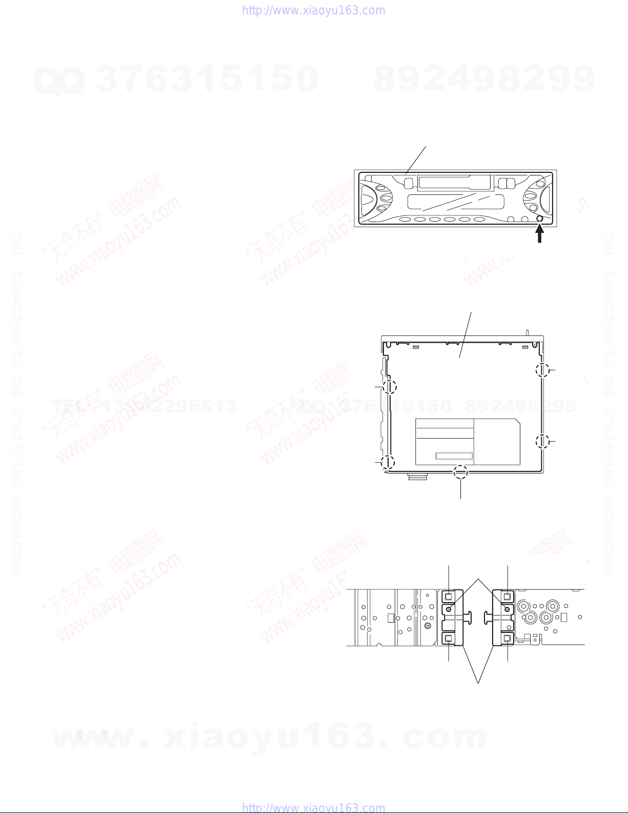
3.1.5 Removing the rear panel
(See Fig.5 )
• Prior to performing the following procedure, remove the front
panel assembly and bottom cover.
(1) Remove the two screws D, three screws Eand three
screws Fattaching the rear panel on the back of the body.
Fig.5
3.1.6 Removing the main board
(See Fig.6)
• Prior to performing the following procedure, remove the front
panel assembly, bottom cover, front chassis, heat sink and
rear panel.
(1) Remove the two screws Gattaching the main board on the
top chassis.
(2) Disconnect the connectors CP701 on the main board from
the cassette mechanism assembly.
Fig.6
3.1.7 Removing the cassette mechanism assembly
(See Fig.7)
• Prior to performing the following procedure, remove the front
panel assembly, bottom cover, front chassis, heat sink, rear
panel and main board.
(1) Remove the four screws Hattaching the cassette mecha-
nism assembly from the top chassis.
Fig.7
Heat sink
C
B
C
ED
EFF
DRear panel
G
Main board
CP701
G
HH
HH
Top chassis
Cassette mechanism assembly
w
w
w
.
x
i
a
o
y
u
1
6
3
.
c
o
m
Q
Q
3
7
6
3
1
5
1
5
0
9
9
2
8
9
4
2
9
8
T
E
L
1
3
9
4
2
2
9
6
5
1
3
9
9
2
8
9
4
2
9
8
0
5
1
5
1
3
6
7
3
Q
Q
TEL 13942296513 QQ 376315150 892498299
http://www.xiaoyu163.com

(No.MA104)1-7
3.1.8 Removing the mecha board
(See Fig.8)
• Prior to performing the following procedure, remove the front
panel assembly, bottom cover, front chassis, heat sink, rear
panel, main board and cassette mechanism assembly.
(1) Disconnect the wire from the connectors CN402 and
CN403 on the mecha board.
(2) Remove the screw Jattaching the mecha board.
Fig.8
3.1.9 Removing the front board
(See Figs.9 to 11)
• Prior to performing the following procedure, remove the front
panel assembly.
(1) Remove the four screws Kattaching the rear cover on the
back of the front panel assembly. (See fig.9)
(2) Release the eleven joints f, the front panel and the rear
cover become separate. (See fig.10)
(3) Remove the front board from the front panel assembly.
(See fig.11)
Caution:
Take care not to lose the springs. Fig.9
Fig.10
Fig.11
J
CN402
CN401 CN403
K
K K
K
Joint f
Joint
f
Joint f
Joint f
Front panel assembly
Rear cover
LCD & Key control board
w
w
w
.
x
i
a
o
y
u
1
6
3
.
c
o
m
Q
Q
3
7
6
3
1
5
1
5
0
9
9
2
8
9
4
2
9
8
T
E
L
1
3
9
4
2
2
9
6
5
1
3
9
9
2
8
9
4
2
9
8
0
5
1
5
1
3
6
7
3
Q
Q
TEL 13942296513 QQ 376315150 892498299
http://www.xiaoyu163.com

1-8 (No.MA104)
3.2 Cassette mechanism assembly
REFERENCE:
Prior to performing the following procedures, turn the mode
gear on the bottom of the body until the respective part comes
to the EJECT position (Refer to Fig.1).
Fig.1
3.2.1 Removing the cassette guide
(See Fig.2)
(1) Turn the mode gear to set to RVS play or subsequent
mode.
(2) Remove the cassette guide from the main chassis while re-
leasing each two joint tabs ain the direction of the arrow.
Fig.2
3.2.2 Removing the load arm
(See Fig.3)
(1) Remove the E-washer attaching the load arm.
(2) Move the load arm in the direction of the arrow and release
the joint bon the cassette catch.
Fig.3
Mode gea
r
Cassette guide
Tab a
Tab a
Load arm
E-washer
Joint b
w
w
w
.
x
i
a
o
y
u
1
6
3
.
c
o
m
Q
Q
3
7
6
3
1
5
1
5
0
9
9
2
8
9
4
2
9
8
T
E
L
1
3
9
4
2
2
9
6
5
1
3
9
9
2
8
9
4
2
9
8
0
5
1
5
1
3
6
7
3
Q
Q
TEL 13942296513 QQ 376315150 892498299
http://www.xiaoyu163.com

(No.MA104)1-9
3.2.3 Removing the cassette hanger assembly / cassette holder
(See Fig.4 to 7)
(1) Check the mode is set to EJECT. Push down the front part
of the cassette holder and move in the direction of the ar-
row to release the joint c.
(2) Move the rear part of the cassette hanger assembly in the
direction of the arrow to release it from the two joint bosses
d.
(3) Release the holder stabilizer spring from the hooks eand
f, then pull out from the cassette hanger assembly.
(4) Bring up the rear side of the cassette hanger assembly to
release the joint gand h.
(5) Pull out the cassette catch from the cassette hanger as-
sembly.
Fig.4
Fig.5
Fig.6
Fig.7
Cassette holder assembly
Side bracket
Joints c
Cassette holder assembly
Cassette hanger
assembly
Boss d
Boss d
Cassette hange
r
assembly
Cassette stabilizer spring
Hook f
Hook e
Cassette hanger
assembly
Hook h
Hook g
Cassette holder
assembly
Cassette holder assembly
Cassette hanger assembly
Cassette catch
w
w
w
.
x
i
a
o
y
u
1
6
3
.
c
o
m
Q
Q
3
7
6
3
1
5
1
5
0
9
9
2
8
9
4
2
9
8
T
E
L
1
3
9
4
2
2
9
6
5
1
3
9
9
2
8
9
4
2
9
8
0
5
1
5
1
3
6
7
3
Q
Q
TEL 13942296513 QQ 376315150 892498299
http://www.xiaoyu163.com

1-10 (No.MA104)
3.2.4 Removing the side bracket assembly
(See Fig.8 to 10)
(1) Remove the screw Aattaching the side bracket assembly.
(2) Detach the front side of the side bracket assembly upward
and pull out forward to release the joint iand jin the rear.
CAUTION:
When reassembling, make sure that the boss kof the
main chassis is set in the notch of the load rack under the
side bracket assembly. Do not reattach the load rack on
the boss k.
CAUTION:
After reattaching the side bracket assembly, confirm op-
eration.
Fig.8
Fig.9
Fig.10
A
Side bracket assembly
Joint i
Joint j
Joint i
Joint j
Side bracket assembly
Boss k
Load rack
Boss k
Load rack
w
w
w
.
x
i
a
o
y
u
1
6
3
.
c
o
m
Q
Q
3
7
6
3
1
5
1
5
0
9
9
2
8
9
4
2
9
8
T
E
L
1
3
9
4
2
2
9
6
5
1
3
9
9
2
8
9
4
2
9
8
0
5
1
5
1
3
6
7
3
Q
Q
TEL 13942296513 QQ 376315150 892498299
http://www.xiaoyu163.com

(No.MA104)1-11
3.2.5 Removing the pinch arm (F) assembly
(See Fig.11 and 12)
(1) Remove the polywasher and pull out the pinch arm (F) as-
sembly.
(2) Remove the compulsion spring.
3.2.6 Removing the pinch arm (R) assembly
(See Fig.11 and 12)
(1) Remove the polywasher and pull out the pinch arm (R) as-
sembly.
3.2.7 Removing the slide chassis assembly
(See Fig.13 and 14)
REFERENCE:
It is not necessary to remove the head and the tape guide.
(1) Move the slide chassis assembly in the direction of the ar-
row to release the two joints land remove from the main
chassis.
(2) Remove the rack link.
CAUTION:
When reassembling, first reattach the rack link, and next
fit the boss mand hook nof the slide chassis assembly
to the hole of the main chassis, and engage the two joints
l.
Fig.11
Fig.12
Fig.13
Fig.14
Polywashe
r
Polywasher Pinch arm
(F) assembly
Pinch arm
(R) assembly
Polywasher
Pinch arm (F) assembly
Compulsion
spring
Pinch arm
(R) assembly Polywasher
Slide chassis assembly
Joint l
Joint l
Boss m
Hook n
Rack link
Head
Tape guide
w
w
w
.
x
i
a
o
y
u
1
6
3
.
c
o
m
Q
Q
3
7
6
3
1
5
1
5
0
9
9
2
8
9
4
2
9
8
T
E
L
1
3
9
4
2
2
9
6
5
1
3
9
9
2
8
9
4
2
9
8
0
5
1
5
1
3
6
7
3
Q
Q
TEL 13942296513 QQ 376315150 892498299
http://www.xiaoyu163.com

1-12 (No.MA104)
3.2.8 Removing the head / tape guide
(See Fig.16 and 17)
REFERENCE:
It is not necessary to remove the slide chassis assembly.
(1) Remove the band attaching the wire to the head.
(2) Remove the two screws B, the head and the head support
spring.
(3) Remove the pinch arm spring from the tape guide.
(4) Remove the tape guide and the pinch spring arm.
CAUTION:
When reattaching the pinch arm spring, set both end of
it to the pinch spring arm (remarked o).
CAUTION:
When reattaching the head, set the wires into the groove
of the tape guide (Fig.16).
3.2.9 Removing the flywheel assembly (F) & (R)
(See Fig.18 and 19)
REFERENCE:
It is not necessary to remove the slide chassis assembly.
(1) Remove the belt at the bottom.
(2) Remove the two polywashers on the upper side.
(3) Pull out each flywheel assembly downward.
Fig.15
Fig.16
Fig.17
Fig.18
B
Slide chassis assembly
Head Tape guide
B
Pinch arm spring
Head
Head support spring
Tape guide
Pinch spring arm
Slid chassis assembly
o
o
Flywheel assembly (F)
Flywheel assembly (R)
Belt
Polywasher
Polywasher
Flywheel assembly (F)
Flywheel assembly (R)
w
w
w
.
x
i
a
o
y
u
1
6
3
.
c
o
m
Q
Q
3
7
6
3
1
5
1
5
0
9
9
2
8
9
4
2
9
8
T
E
L
1
3
9
4
2
2
9
6
5
1
3
9
9
2
8
9
4
2
9
8
0
5
1
5
1
3
6
7
3
Q
Q
TEL 13942296513 QQ 376315150 892498299
http://www.xiaoyu163.com

(No.MA104)1-13
3.2.10 Disassembling the flywheel assembly (F)
(See Fig.19 and 20)
(1) Push and turn counterclockwise the spring holder (F) to re-
lease the three joints pon the bottom of the flywheel.
(2) The spring holder (F), the TU spring and the friction gear
play come off.
(3) Remove the polywasher and felt.
3.2.11 Disassembling the flywheel assembly (R)
(See Fig.19 and 20)
(1) Push and turn clockwise the spring holder (R) to release
the three joints qon the bottom of the flywheel.
(2) The spring holder (R), the FF spring and the friction gear
FF come off.
(3) Remove the polywasher and the felt.
3.2.12 Removing the reel board
(See Fig.21 and 22)
(1) Remove the two screws Cattaching the reel board.
(2) Move the reel board in the direction of the arrow to release
the joint r.
(3) Unsolder the wires if necessary.
CAUTION:
When reattaching, confirm operation of the MODE
switch and the ST-BY switch.The mode position be-
tween EJECT and ST-BY is optimum for reattach-
ing.Connect the card wire extending from the reel board
to the FFC pad before reattaching the reel board.
Fig.19
Fig.20
Fig.21
Fig.22
Flywheel
assembly (F) Flywheel
assembly (R)
Joints p
Joint p
Joints q
Joint q
Polywasher
Spring holder (F)
TU spring
Polywasher
Spring holder (R)
FF spring
Friction gear play
Friction gear FF
Flywheel assembly (F)
Flywheel assembly (R)
Felt Felt
FFC pad
Joint
r
Reel board
C
C
FFC pad
CT-1 switch
ST-BY switch
Soldering
MODE switch
w
w
w
.
x
i
a
o
y
u
1
6
3
.
c
o
m
Q
Q
3
7
6
3
1
5
1
5
0
9
9
2
8
9
4
2
9
8
T
E
L
1
3
9
4
2
2
9
6
5
1
3
9
9
2
8
9
4
2
9
8
0
5
1
5
1
3
6
7
3
Q
Q
TEL 13942296513 QQ 376315150 892498299
http://www.xiaoyu163.com

1-14 (No.MA104)
3.2.13 Removing the gear base arm / gear base link assembly
(See Fig.23 to 25)
(1) Move the gear base arm in the direction of the arrow.
(2) Insert a slotted screwdriver to the gear base spring under
the gear base arm, and release the gear base arm upward
from the boss on the gear base assembly.
(3) Remove the gear base arm from the main chassis while re-
leasing the two joints s.
(4) Move the gear base link assemby in the direction of the ar-
row to release the two joints t.
REFERENCE:
When reattaching the gear base arm, make sure that the
boss on the gear base assembly is inside the gear base
spring.
3.2.14 Removing the FFC pad
(See Fig.25 and 27)
(1) Push each joint hook uof the FFC pad and remove toward
the bottom.
Fig.23
Fig.24
Fig.25
Gear base
link assembly
Gear base arm
FFC pad
Joint t
Joint t
Joints s
Hook u
Hook u
Gear base arm
Screwdriver
Gear base spring
FFC pad
Gear base link
assembly Gear base arm
w
w
w
.
x
i
a
o
y
u
1
6
3
.
c
o
m
Q
Q
3
7
6
3
1
5
1
5
0
9
9
2
8
9
4
2
9
8
T
E
L
1
3
9
4
2
2
9
6
5
1
3
9
9
2
8
9
4
2
9
8
0
5
1
5
1
3
6
7
3
Q
Q
TEL 13942296513 QQ 376315150 892498299
http://www.xiaoyu163.com

(No.MA104)1-15
3.2.15 Removing the mode gear
(See Fig.26 and 29)
(1) Remove the polywasher on the bottom and pull out the
mode gear.
3.2.16 Removing the mode switch actuator
(See Fig.26, 27 and 29)
(1) Pull out the mode switch actuator at the bottom.
REFERENCE:
When reattaching the mode switch actuator to the main
chassis, make sure to set on the shaft and insert vinto
the slot w.
3.2.17 Removing the direction link / direction plate
(See Fig.27 to 29)
(1) Remove the polywasher attaching the direction link.
(2) Bring up the direction link to release the three joints x, y
and zat a time.
(3) Move the direction plate in the direction of the arrow to re-
lease the two joints a’.
REFERENCE:
When reattaching the direction plate, engage the two
joints a’ and move in the direction of the arrow (Refer to
Fig.28).
REFERENCE:
When reattaching the direction link, move the direction
plate in the direction of the arrow and engage the three
joint x, yand zat a time (Refer to Fig.29).
3.2.18 Removing the mode rack assembly
(See Fig.27 and 28)
(1) Move the mode rack assembly in the direction of the arrow
to release the two joints b’ and the joint c’.
REFERENCE:
When reattaching, set the two b’ on the bottom of the
mode rack assembly into the slots of the main chassis
and move in the direction of the arrow (See Fig.28).
Fig.26
Fig.27
Fig.28
Fig.29
Polywashe
r
Mode switch actuator Mode gear
Direction plate Direction link
Mode rack assembly
Slot w
Direction plate
Joints a'
Joint z
Direction link Polywasher
Joint y
Joint x
Direction plate Mode rack assembly
Joint c'
Joint b'
Joint b'
Joints a'
Polywasher
Mode gea
r
Mode switch actuator
Direction link
Direction plate
Mode rack assembly
v
w
w
w
.
x
i
a
o
y
u
1
6
3
.
c
o
m
Q
Q
3
7
6
3
1
5
1
5
0
9
9
2
8
9
4
2
9
8
T
E
L
1
3
9
4
2
2
9
6
5
1
3
9
9
2
8
9
4
2
9
8
0
5
1
5
1
3
6
7
3
Q
Q
TEL 13942296513 QQ 376315150 892498299
http://www.xiaoyu163.com

1-16 (No.MA104)
3.2.19 Removing the gear base assembly / take up gear / reflector gear
(See Fig.30 to 32)
(1) Push in the pin d’ of the gear base assembly on the upper
side of the body and move the reflector gear toward the
bottom, then pull out.
(2) Remove the polywasher on the bottom and pull out the
take up gear.
(3) Move the gear base assembly in the direction of the arrow
to release it from the two slots e’ of the main chassis.
REFERENCE:
The parts are damaged when removed. Please replace
with new ones.
3.2.20 Removing the reel driver / reel spindle
(See Fig.32)
(1) Draw out the reel driver from the shaft on the main chassis
and remove the reel driver spring and the reel spindle re-
spectively.
CAUTION:
The reel driver is damaged when removed. Please re-
place with a new one.
Fig.30
Fig.31
Fig.32
Gear base assembly
Pin d'
Slot e'
Slot e'
Polywasher
Reflector gear
Take up gear
Reel driver spring
Reel driver spring
Reel driver
Reel driver
Reel spindle
Reel spindle
Gear base assembly
Slots e’
Main chassis
Reflector gear Polywasher
Take up gea
r
w
w
w
.
x
i
a
o
y
u
1
6
3
.
c
o
m
Q
Q
3
7
6
3
1
5
1
5
0
9
9
2
8
9
4
2
9
8
T
E
L
1
3
9
4
2
2
9
6
5
1
3
9
9
2
8
9
4
2
9
8
0
5
1
5
1
3
6
7
3
Q
Q
TEL 13942296513 QQ 376315150 892498299
http://www.xiaoyu163.com

(No.MA104)1-17
3.2.21 Removing the side bracket assembly
(See Fig.33 to 37)
(1) Remove the eject cam plate spring.
(2) Push the joint f’ through the slot to remove the load rack
downward.
(3) Move the eject cam limiter in the direction of the arrow to
release it from the boss g’ of the side bracket assembly and
from the two joints h’.
(4) Move the eject cam plate in the direction of the arrow to re-
lease the joint i’.
CAUTION:
When reassembling, confirm operation of each part be-
fore reattaching the eject cam plate spring.
Fig.33
Fig.34
Fig.35
Fig.36
Fig.37
Joint f'
Load rack
Eject cam plate spring
Eject cam limiter
Side bracket assembly
Boss g'
Joint h'
Load rack
Joint f'
Joint h'
Boss g'
Eject cam limiter
Side bracket
assembly
Joint h'
Joint h'
Eject cam plate
Side bracket assembly
Boss g'
Joint i'
Eject cam plate
Side bracket assembly
Eject cam plate
Joint i'
w
w
w
.
x
i
a
o
y
u
1
6
3
.
c
o
m
Q
Q
3
7
6
3
1
5
1
5
0
9
9
2
8
9
4
2
9
8
T
E
L
1
3
9
4
2
2
9
6
5
1
3
9
9
2
8
9
4
2
9
8
0
5
1
5
1
3
6
7
3
Q
Q
TEL 13942296513 QQ 376315150 892498299
http://www.xiaoyu163.com

1-18 (No.MA104)
3.2.22 Removing the main motor assembly / sub motor assembly
(See Fig.38 to 40)
(1) Remove the belt at the bottom.
(2) Remove the polywasher and pull out the mode gear.
(3) Pull out the reduction gear (B).
(4) Remove the polywasher and pull out the reduction gear
(A).
(5) Remove the two screws attaching the main motor assem-
bly.
(6) Remove the two screws Eattaching the sub motor assem-
bly.
(7) Unsolder the wires on the reel board if necessary.
CAUTION:
When reassembling, adjust the length of the wires ex-
tending from the sub motor asswmbly by attaching them
to the side of the sub motor assembly with the wires ex-
tending from the main motor assembly using a spacer.
Fig.38
Fig.39
Fig.40
Belt
Polywasher
Polywashe
r
Mode gear
Reduction
gear (A)
Main motor
assembly
D
Sub moto
r
assembly
E
Reduction gear (B)
Polywasher
Reduction gear (B)
Reduction gear (A)
ED
Main motor assembly
Sub motor assembly
Spacer
Space
r
Sub motor assembly
Main motor assembly
w
w
w
.
x
i
a
o
y
u
1
6
3
.
c
o
m
Q
Q
3
7
6
3
1
5
1
5
0
9
9
2
8
9
4
2
9
8
T
E
L
1
3
9
4
2
2
9
6
5
1
3
9
9
2
8
9
4
2
9
8
0
5
1
5
1
3
6
7
3
Q
Q
TEL 13942296513 QQ 376315150 892498299
http://www.xiaoyu163.com

(No.MA104)1-19
SECTION 4
ADJUSTMENT
4.1 Adjustment method
Test instruments required for adjustment
(1) Digital oscilloscope (100MHz)
(2) Frequency counter meter
(3) Electric voltmeter
(4) Wow & flutter meter
(5) Test tapes
• VT724...........................For DOLBY level measurement
• VT739..............For playback frequency measurement
• VT712....For wow flutter & tape speed measurement
• VT703........................For head azimuth measurement
(6) Torque gauge............................Cassette type for CTG-N
Standard volume position
Balance and Bass, Treble volume, Fader : Center (Indication "0")
Loudness, Dolby NR, Sound, Cruise : Off
Volume position is about 2V at speaker output with following
conditions, Playback the test tape VT721.
Measuring conditions (Amplifier section)
AM mode 999kHz/62dB, INT/400Hz, 30%
modulation signal on receiving.
FM mono mode 97.9MHz/66dB, INT/400Hz, 22.5kHz
deviation pilot off mono
FM stereo mode 1kHz, 67.5kHz dev. pilot 7.5kHz dev.
Output level 0dB (1µV,50Ω/open terminal)
Power supply voltage: DC14.4V (11V to 16V)
Load impedance: 4Ω(4Ωto 8Ωallowance)
Line out level/Impedance: 2.0V/20kΩload (250 nWb/m)
w
w
w
.
x
i
a
o
y
u
1
6
3
.
c
o
m
Q
Q
3
7
6
3
1
5
1
5
0
9
9
2
8
9
4
2
9
8
T
E
L
1
3
9
4
2
2
9
6
5
1
3
9
9
2
8
9
4
2
9
8
0
5
1
5
1
3
6
7
3
Q
Q
TEL 13942296513 QQ 376315150 892498299
http://www.xiaoyu163.com

1-20 (No.MA104)
Information for using a car audio service jig
(1) We're advancing efforts to make our extension cords common for all car audio products.
Please use this type of extension cord as follows.
(2) As a U-shape type top cover is employed, this type of extension cord is needed to check operation of the mechanism assembly
after disassembly.
(3) Extension cord : EXTKSRT002-18P ( 18 pin extension cord ) For connection between mechanism assemblyand main board.
(4) Check for mechanism driving section such as motor ,etc.
Disassembly method
(1) Remove the front panel assembly.
(2) Remove the bottom cover.
(3) Remove the front chassis.
(4) Remove the rear panel
(5) Remove the heat sink.
(6) Remove the main board.
(7) Reattach the heat sink with the two screws B. (Refer to DISASSEMBLY.)
(8) Install the front chassis and front panel assembly.
(9) Confirm that current is being carried by connecting an extension cord jig.
NOTE:
Available to connect to the CJ701 connector when installing the front panel.
CAUTION :
Be sure to attach the heat sink and rear panel on the power amplifier IC and regulator IC of a main board when supplying
the power.If voltage is applied without attaching those parts, the power amplifier IC and regulator IC will be destroyed
by heat.
Front panel assembly
Extension cord
EXTKSRT002-18P
Main board
Cassette mechanism
EXTKSRT002-18P
To
Main board
To
Cassette mechanism
w
w
w
.
x
i
a
o
y
u
1
6
3
.
c
o
m
Q
Q
3
7
6
3
1
5
1
5
0
9
9
2
8
9
4
2
9
8
T
E
L
1
3
9
4
2
2
9
6
5
1
3
9
9
2
8
9
4
2
9
8
0
5
1
5
1
3
6
7
3
Q
Q
TEL 13942296513 QQ 376315150 892498299
http://www.xiaoyu163.com
Table of contents
Other JVC Stereo Receiver manuals