JVC AV 27D302 User manual

COLORTELEVISION
USER'SGUIDE
Formodels:
AV-27D302
AV-27D202
AV-20D202
AV-27230
Illustration ofAV-27D302 and RM-C303G
IMPORTANT NOTE TO THE CUSTOMER
In the sp ac es below,enter the modeland serialnumb er ofyour television (loc ated
atthe rear ofthe television c abinet).Sta ple your sales re ceiptor invoice to the
insid e cover ofthis guid e.K ee p this user's guide in a convenientpla ce for
future reference.K ee p the c arton and originalp acka ging for future use.
Mod elNumber
SerialNumber
LC T 0 92 4 -0 0 1A -A
0 10 1 -T N -JII-JIM
FD mini-IB 1/16/01 3:33 PM Page 1
All manuals and user guides at all-guides.com
all-guides.com

IMPORTANT SAFETY PRECAUTIONS
WARNING: TO PREVENT FIRE OR SH O C K HAZARDS,D O N OT
EXPOSE THIS TV SET TO RAIN OR MOISTURE.
CAUTION: TO INSURE PERSO N AL SAFETY,O BSERVE THE
F OLLO WIN G RULES RE G ARDIN G TH E USE O F
THIS U NIT.
1.O p erate only from the power sourc e specifie d on the unit.
2.Avoid damaging the AC plug and power cord.
3.Avoid Improp er installation and never position the unitwhere good
ventilation is unattaina ble.
4.Do notallow obje cts or liquid into the ca binetopenings.
5.In the eventoftrouble,unplug the unitand c all a service technician.
Do notattemptto re pair ityourselfor remove the re ar cover.
Changes or modifications notapproved by JVC could void the warranty.
*When you don’tuse this TV setfor a long p eriod oftime,b e sure to
disconne ctboth the power plug from the A C outletand antenna for
your safety.
*To preventelectric shock do notuse this polarize d plug with an
extension cord,receptacle or other outletunless the bla des c an b e
fully inserte d to preventblad e exposure.
CAUTION:To reduce the risk of electric shock.
Do not remove cover (or back).
No user serviceable parts inside.
Refer servicing to qualified service personnel.
The lightning flash with arrowhead symbol,
within an equilateral triangle is intended to alert
the user to the presence of uninsulated “dan-
gerous voltage” within the product’s enclosure
that may be of sufficient magnitude to consti-
tute a risk of electric shock to persons.
The exclamation point within an e quilatera l tri-
angle is intended to alert the use r to the pres-
ence of important operating and m aintenance
(se rvicing) instructions in the literature accom-
panying the appliance.
RISK OF ELECTRIC SHOCK
DO NOT OPEN
CAUTION
FD mini-IB 1/16/01 3:33 PM Page 2
All manuals and user guides at all-guides.com

IMPORTANT SAFEGUARDS
CAUTION:
Please read and retain for your safety.
Electricalenergy c an p erform many usefulfunctions.This TV sethas b een engineere d
and manufacture d to assure your personalsafety.But
improper use can resultin poten-
tialele ctric alshock or fire ha zards.
In ord er notto d efe atthe safe guards incorporated in
this TV set, observe the following b asic rules for its installation,use and servicing.
And also follow all warnings and instructions marked on your TV set.
INSTALLATION
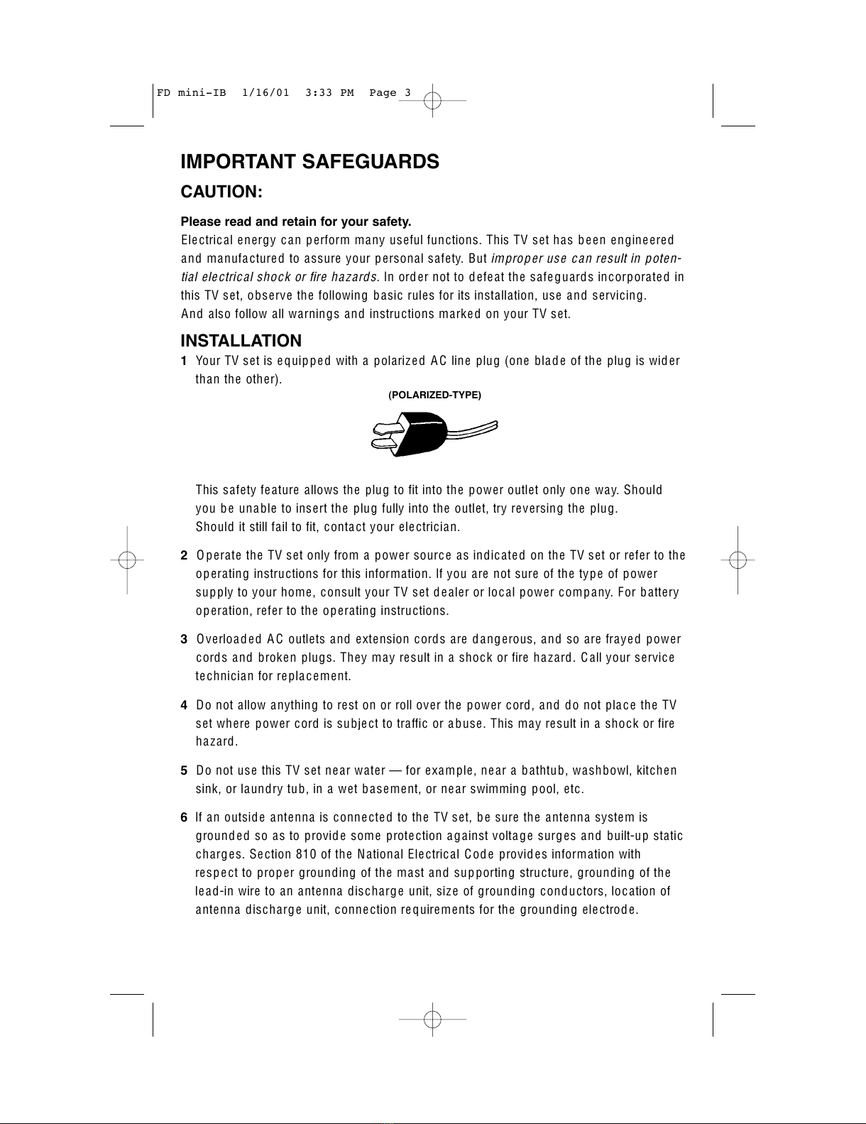
1Your TV setis equip pe d with a polariz ed A C line plug (one blad e ofthe plug is wid er
than the other).
This safety feature allows the plug to fitinto the power outletonly one way.Should
you be una ble to insertthe plug fully into the outlet, try reversing the plug.
Should itstill fail to fit, conta ctyour ele ctrician.
2O p erate the TV setonly from a power sourc e as indicated on the TV setor refer to the
op erating instructions for this information.Ifyou are notsure ofthe type ofpower
sup ply to your home,consultyour TV setd ealer or loc alpower comp any.For b attery
op eration,refer to the op erating instructions.
3Overload ed A C outlets and extension cords are d ang erous,and so are fraye d power
cords and broken plugs.They may resultin a shock or fire haz ard.C all your service
technician for re placement.
4Do notallow anything to reston or roll over the power cord,and do notplac e the TV
setwhere power cord is subjectto traffic or abuse.This may resultin a shock or fire
haz ard.
5Do notuse this TV setne ar water —for example,near a bathtub,washbowl,kitchen
sink,or laundry tub,in a wetb asement, or near swimming pool,etc.
6Ifan outsid e antenna is conne cte d to the TV set, be sure the antenna system is
grounde d so as to provid e some prote ction a gainstvoltage surges and built-up static
charg es.Se ction 810 ofthe NationalElectricalCod e provid es information with
respe ctto proper grounding ofthe mastand supporting structure,grounding ofthe
lea d-in wire to an antenna discharg e unit, siz e ofgrounding conductors,loc ation of
antenna discharge unit, connection re quirements for the grounding ele ctrod e.
(POLARIZED-TYPE)
FD mini-IB 1/16/01 3:33 PM Page 3
All manuals and user guides at all-guides.com

7An outsid e antenna system should notb e located in the vicinity ofoverhead power
lines or other ele ctric lightor power circuits,or where itc an fall into such power lines
or circuits.When installing an outsid e antenna system,extreme c are should b e taken
to kee p from touching such power lines or circuits as conta ctwith them mightb e
fatal.
8TV sets are provid ed with ventilation openings in the c abinetto allow he atgenerated
during operation to be rele ase d.
Therefore:
—Never block the bottom ventilation slots ofa portable TV setby placing iton a
bed,sofa,rug,etc.
—Never plac e a TV setin a “built-in”enclosure unless proper ventilation is provide d.
—Never cover the openings with a cloth or other material.
—Never plac e the TV setne ar or over a ra diator or heatre gister.
9To avoid p ersonalinjury:
—Do notplac e a TV seton a sloping shelfunless prop erly secure d.
—Us e only a c artor sta nd re c omm en d e d b y th e TV s etm anufa cturer.
—Do nottry to roll a cartwith small c asters across thresholds or d ee p pile carp ets.
—Wall or shelfmounting should follow the manufa cturer’s instructions,and should
use a mounting kita pproved by the manufacturer.
USE
10 Caution children aboutdropping or pushing objects into the TV setthrough cabinetopenings.
Some internalparts carry hazardous voltages and contactcan resultin a fire or electricalshock.
11 Unplug the TV setfrom the wall outletb efore cleaning.Do notuse liquid or an
aerosolcleaner.
12 Never a dd a cc essories to a TV setthathas notb een d esigned for this purpose.
Such a dditions may resultin a haz ard.
EXAMPLE OF ANTENNA GROUNDING
AS PER NATIONAL ELECTRICAL CODE
FD mini-IB 1/16/01 3:33 PM Page 4
All manuals and user guides at all-guides.com

13 For added protection ofthe TV setduring a lightning storm or when the TV setis to be left
unattended for an extended period oftime,unplug itfrom the wall outletand disconnect
the antenna.This will preventdamage to productdue to lightning storms or power line
surges.
14 A TV setand cartcombination should be moved with
care.Quick stops,excessive force,and uneven sur-
faces may cause the TV setand cartcombination to
overturn.
SERVICE
15 Unplug this TV setfrom the wall outletand refer servicing to qualifie d service per-
sonnelunder the following conditions:
A.When the power cord or plug is d ama ge d or frayed.
B.Ifliquid has be en spilled into the TV set.
C.Ifthe TV sethas been expose d to rain or water.
D.Ifthe TV setdoes notoperate normally by following the operating instructions.
Adjustonly those controls thatare covere d in the op erating instructions as
improper a djustmentofother controls may resultin damage and will often re quire
extensive work by a qualified te chnician to restore the TV setto normalop eration.
E.Ifthe TV sethas b een dropp ed or damaged in any way.
F.When the TV setexhibits a distinctchange in p erformance —this indicates a
nee d for service.
16 Do notattemptto servic e this TV setyourselfas opening or removing covers may
expose you to dang erous volta ge or other hazards.Refer all servicing to qualified
servic e personnel.
17 When repla cementparts are re quire d,have the servic e technician verify in writing
thatthe re pla cementp arts he uses have the same safety characteristics as the orig-
inalp arts.Use ofmanufa cturer’s spe cifie d repla cementparts can preventfire,
shock,or other haz ards.
18 Upon completion ofany service or repairs to this TV set, please ask the service techni-
cian to perform the safety check described in the manufacturer’s service literature.
19 When a TV setreaches the end ofits usefullife,improper disposalcould resultin a pic-
ture tube implosion.Ask a qualified service technician to dispose ofthe TV set.
20 Note to C ATV system installer.
This reminder is provid ed to c all the C ATV system installer’s attention to Article 820-
40 ofthe N E C thatprovides guid elines for proper grounding and,in particular,spec-
ifies thatthe cable ground shall b e conne cted to the grounding system ofthe build-
ing,as close to the pointofc able entry as practical.
FD mini-IB 1/16/01 3:33 PM Page 5
All manuals and user guides at all-guides.com

MENU POW E R
ONTIME R
–C H A N N E L + – V O LU M E +
OPER A T E
PO W ER
DI S P LA Y
SL E E P T IM E R
LIG H T
BBE
VID E O ST A T U S
IN PU T
1
7
4
100+
3
9
6
RETURN+
MU T I N G
ME N U
V C H I P
EX IT
2
8
0
5
+
CH
VO L VO L
+
CH
RE C ST O P PA U S E
PL AY F FRE W
TV
CA T V DV D
VC R
VC R C H A N N E L
TV /V C R
VC R /D V D
PO W E R
PR E V NEX T
OP E N / C LO S E ST I LL/ P AU S E
RM - C 3 03 G
HY P E R S U R R O U N D
TV
Two AA
Batteries
1 Television
1 R em ote
C ontrol
Thank you for your purchase of a JVC Color Television. Before you begin setting up your new television,
please check to make sure you have all of the following items. In addition to this guide, your television
box should include:
O nce you have unpacked your television, the next step is to connect it to your antenna/cable or
satellite system and to connect the audio/video device s you want to use with your television. To
make these connections you will use plugs like the ones illustra ted below.
A/V Input Plug
RF Connectors
U sed to connect a
coaxial cable from an
external antenna or
C able T V syste m.
A matching TV stand
for the 27 inch models
is also available
(optional).
U sed to m ake video
conne ctions with V C R s,
D V D s, C am corders, etc
(optional).
U sed to connect
audio/video devices like
V C R s, D V D playe rs,
stereo amplifiers, ga me
consoles, e tc.
S-Video Plug
W e recommend that be fore you start using your new television, you read your entire U se r’s Guide
so you ca n le a rn about your new te le vision’s ma ny great feature s. But if you’re anxious to start
using your television right away, a quick setup guide follows on the next three pages.
Unpacking Your Television
6
Note: Your television
and/or remote control may
differ from the examples
illustrated here.
FD mini-IB 1/16/01 3:33 PM Page 6
All manuals and user guides at all-guides.com
all-guides.com

7
Slide the cover on the back of the remote down towards the bottom of the remote control. Inse rt two
ba tteries (included) carefully noting the “+” a nd “–” markings, placing the “–” end in the unit first.
Slide the cover back into place.
Getting Started
These quick se tup pages will provide you, in three ea sy steps, with the basic information you ne e d
to be gin using your new television right away. This inform ation includes basic instructions on
opera ting your rem ote control, making a sim ple cable/antenna and optional VC R connection and,
fina lly, information on programming your tele vision's Auto Tuner.
If you have que stions, or for more detailed inform ation on any of the se steps, please consult other
sections of this m a nual.
Step One - The Remote Control
The remote control is the key to operating your tele vision's m a ny gre a t fea tures. Before you ca n
opera te your rem ote control, you first ne e d to install the ba tteries (included).
Basic Operation
Turn the television on a nd off by pressing the PO W E R button at the top right corner of the rem ote.
The four key fea ture buttons at the cente r of the remote can be used for basic opera tion of the
television. The top a nd bottom buttons will scan forward a nd back through the available channels.
The right and left buttons will turn the volume up or down. These buttons are also marked with four
arrows and a re also used with JV C 's onscreen menu syste m . You will need to use these buttons
later in the Q uick Setup.
The next ste p is to connect your television to a n a ntenna or cable.
P O W E R
M U T IN G
M E N U
V C H IP
E X IT
+
CH
V O L V O L
+
CH
Power Button
Key Feature Buttons
!
Proceed to S tep Two
Quick Setup 1
FD mini-IB 1/16/01 3:33 PM Page 7
All manuals and user guides at all-guides.com

8
75Ω
(VHF/ U H F )
INPUT 1 INP U T 2
S-VID E O
VIDEO VI D E O /Y
COMP O N E N T
VIDEO
OVER
AUDIOO UT
L
R
RR
AUDIO
75Ω
(V H F / U H F)
IN P U T 2
V ID E O / Y
C O M P O N E N T
V ID E O
AUDIO OUT
L
R
R
IN P U T 1
S -V I D E O
V ID E O
O V E R
R
AUDIO
W AL L
C AB LE or AN T E N N A
O U T
75Ω
(VHF/U H F )
INPUT 1 INPUT 2
S-VIDE O
VIDEO VIDEO/ Y
COMPO N E N T
VIDEO
OVER
AUDIOOUT
L
R
RR
AUDIO
75Ω
(V H F / U H F)
IN P U T 2
V ID E O / Y
C O M P O N E N T
V ID E O
AUDIO OUT
L
R
R
IN P U T 1
S -V I D E O
V ID E O
O V E R
R
AUDIO
OR
V C R
IN
OR
C able/R F conne ctor
AV C a ble s/P lugs
Step Two - Making Basic Connections
N e xt you will ne e d to connect your television to an antenna or ca ble system. The most ba sic
ante nna/cable connection is shown below. F or more de tailed connections, such a s one s whe re a
cable box is required, se e page s 11 and 12.
You may also wish to connect a VC R at this point. A basic VCR connection is shown below. For detailed
instructions on connecting a other components or a home theater system, see pages 13 and 14.
Note: A V C R is not required to opera te your television.
1) C onnect the yellow vide o cable out from the VC R’s Video O utput, in to the T V’s Vide o Input
jack, OR connect an S -V ideo ca ble from the VC R’s S-V ide o output, to the T V’s S -Vide o input.
2) C onnect the white audio cable out from the V CR ’s Le ft Audio O utput, in to the TV ’s Left Audio
Input Jack.
3 ) C onne ct the re d a udio ca ble out from the V C R ’s R ight Audio O utput, in to the T V ’s R ight
Audio Input jack.
Fina lly, once you ha ve finished your conne ctions, plug the powe r cord into the nearest power outlet
and turn on the television.
1) C onnect an R F cable out from the wall outlet in to the RF Input on the back of the T V.
!
Proceed to S tep Three
Quick Setup 2
Illustration ofAV-27D302
FD mini-IB 1/16/01 3:33 PM Page 8
All manuals and user guides at all-guides.com

9
STOP
The Q uick Setup
is complete
Quick Setup 3
P ress the M E N U button on the re m ote control.
Press the
!"
buttons to move to AU T O TU N E R S E TU P
Press the
#$
buttons to be gin AU T O TU N E R S E T U P
#$
To choose C ABLE (if you are connected to a cable system) or AIR (if you use an antenna)
!"
To move to START
#$
To start Auto Tuner S etup
The Auto Tuner will now memorize all of the clear, active channels your television can receive. This
will take one or two minutes.
N
O
W
P
R
O
G
R
AMMI
N
G
!
48
T
U
N
E
R
M
OD
E: CAB
L
EAI
R
S
TA
R
T
Step Three - Auto Tuner Setup
JV C’s onscreen menu system lets you set your television up to meet your own personal vie wing
prefere nces. The menu screens and their feature s are discussed in detail in this book. The menu
settings are optional, you can se t as m a ny or as fe w of them as you wish. But to begin watching
your tele vision right away you will need to run the Auto Tune r Setup. This lets your television learn
the channels it is able to receive. To run the Auto Tuner S e tup follow the ste ps below.
T he Auto Tune r is finishe d whe n the messa ge P R O G R AM M IN G O V E R ! a ppe ars onscre en.
The Auto Tuner programming is now complete. You can now begin watching your television, or you can
continue on in this guide for more information on connecting audio/video devices, programming your
remote control, or using the JVC onscreen menu system to customize your television viewing experience.
FD mini-IB 1/16/01 3:33 PM Page 9
All manuals and user guides at all-guides.com

Table of Contents
Quick Setup Guide ....7
CONNECTIONS
C a ble and V C R C onnections .......11
Conne cting to a DVD Player .......13
He a dphone C onne ction . . . . . . . . . 13
Conne cting to an ExternalAmplifier . . . 14
Conne cting to a C amcord er . . . . . . . 14
GETTING STARTED
Remote C ontrol
Remote C ontrolB asics
. . . . . 15
Changing the B atteries
. . . . . 15
Remote Programming ..........16
C ATV an d S atellite C odes. . . . . . . . . 16
VCR C odes ................17
DVD Cod es ................18
MENU FUNCTIONS
Using the Guid e .............19
Auto Tuner S etup............20
C h ann elSummary............21
V-C hip...................22
SetLock Code
. . . . . . . . . 29
Picture Settings
Tint
. . . . . . . . . . . . . . . 30
Color
..............30
Picture
.........30
Bright
.............30
D etail
.............30
Noise Muting
.........31
SetVid eo Status
. . . . . . . . 31
Sound Settings
Bass
. . . . . . . . . . . . . . 32
Tre ble
.............32
Balance
............32
MTS (Multi-channelSound)
. . 33
TV Sp eaker
..........33
G eneralItems
Auto Clock Set
.........34
ManualClock Set
. . . . . . . 35
On/Off Timer
..........36
L an g ua g e
...........37
Clos ed C a ption
. . . . . . . . 37
B a c kgroun d
. . . . . . . . . . 38
V2 C om pon ent-In
.......38
BUTTON FUNCTIONS
Menu. . . . . . . . . . . . . . . . . . . 39
Exit....................39
Display ..................39
Video Status . . . . . . . . . . . . . . . 40
Slee p Timer ................40
Hyper Surround . . . . . . . . . . . . . 40
Muting ..................40
BBE....................41
100 + ...................41
Return +. . . . . . . . . . . . . . . . . . 41
In put...................41
VCR Buttons . . . . . . . . . . . . . . . 42
DVD Buttons . . . . . . . . . . . . . . . 42
TV/C ATV Switch . . . . . . . . . . . . . 42
VCR/DVD Switch . . . . . . . . . . . . . 42
Light...................42
APPENDICES
Troubleshooting .............43
Warranty .................44
Authorize d Servic e C enters .......46
Se arch Cod es. . . . . . . . . . . . . . . 47
Sp ecific ations...............48
FD mini-IB 1/16/01 3:33 PM Page 10
All manuals and user guides at all-guides.com

Connections
Cable and VCR Connections
11
75Ω
(VHF/U H F )
INPUT 1 INP U T 2
S-VIDE O
VIDEO VIDEO/Y
COMP O N E N T
VIDEO
OVER
AUDIOOUT
L
R
RR
AUDIO
75Ω
(V H F / U H F)
IN P U T 2
V ID E O / Y
C O M P O N E N T
V ID E O
AUDIO OUT
L
R
R
IN P U T 1
S -V I D E O
V ID E O
O V E R
R
AUDIO
V C R
IN
W A LL
C AB LE or AN T E N N A
O U T
OR
OR
1) C onnect the antenna or cable TV wire from the wall outlet, to the R F Input of the V C R .
2 ) C onne ct a n R F ca ble from the R F O utput of the V C R , to the R F Input on the ba ck of the
television.
3) C onnect the yellow vide o cable out from the VC R’s Video O utput, in to the T V’s Vide o Input
jack, OR connect an S -V ideo ca ble from the VC R’s S-V ide o O utput, to the T V’s S-V ideo Input.
4) C onnect the white audio cable out from the V CR ’s Le ft Audio O utput, in to the TV ’s Left Audio
Input Jack.
5 ) C onne ct the re d a udio ca ble out from the V C R ’s R ight Audio O utput, in to the T V ’s R ight
Audio Input jack.
• If your V C R is a m ono sound unit, it will ha ve only one Audio O ut jack. C onnect it to the T V ’s
Le ft Audio Input.
• Plea se consult your VC R’s use rs guide for more inform a tion on its opera tion.
• If you do not have a VC R, connect the R F cable directly into the RF input at the ba ck of the
television. For an illustration of this connection, see page 8 in the Q uick S etup se ction.
There are two ba sic types of antenna or cable connections:
• If you have an ante nna or ha ve a cable system tha t does not require you to use a cable box to
se lect cha nne ls, ple ase re fer to D iagra m #1 .
• If you have a cable system that re quires the use of a ca ble box to a ccess any or all the
cha nne ls, ple ase re fer to D iagra m #2 .
• F or your convenience, conne ction to a VC R is also shown in the following diagrams. A VC R is
not necessary to use your television. You may omit the VC R from your conne ctions if you wish.
Diagram #1
Illustration ofAV-27D302
FD mini-IB 1/16/01 3:33 PM Page 11
All manuals and user guides at all-guides.com
all-guides.com

Connections
12
The connection diagrams are intended to show some basic general connections. Some
cable companies may require special connections to properly use your television. If you
follow these diagrams and the television does not work properly, contact your local cable
operator for more connection information.
Cable and VCR Connections - Continued
75Ω
(VHF/U H F )
INPUT 1 INP U T 2
S-VIDE O
VIDEO VIDEO/Y
COMP O N E N T
VIDEO
OVER
AUDIOOU T
L
R
RR
AUDIO
75Ω
(V H F / U H F)
IN P U T 2
V ID E O / Y
C O M P O N E N T
V ID E O
AUDIO OUT
L
R
R
IN P U T 1
S -V I D E O
V ID E O
O V E R
R
AUDIO
V C R
IN
OR
W A LL
C AB LE or AN T E N N A
O U T
OR
1) C onnect the antenna or cable TV wire from the wall outlet, to the R F Input of the ca ble box.
2) C onnect an RF ca ble from the R F O utput of the ca ble box, to the R F Input on the back of
the V C R .
3 ) C onne ct a n R F ca ble from the R F O utput of the V C R , to the R F Input on the ba ck of the T V.
4) C onnect the yellow vide o cable out from the VC R’s Video O utput, in to the T V’s Vide o Input
jack, OR connect an S -V ideo ca ble from the VC R’s S-V ide o O utput, to the T V’s S-V ideo Input.
5) C onnect the white audio cable out from the V CR ’s Le ft Audio O utput, in to the TV ’s Left Audio
Input jack.
6 ) C onne ct the re d a udio ca ble out from the V C R ’s R ight Audio O utput, in to the T V ’s R ight
Audio Input jack.
• If your V CR is a mono sound unit, it will have only one Audio O ut jack. C onne ct it to the TV ’s
Le ft Audio Input.
• P lease consult your VC R ’s user’s guide for more information on its operation.
• If you do not have a V CR , conne ct the R F cable from the ca ble box directly into the R F input
at the back of the television.
Diagram #2
Illustration ofAV-27D302
FD mini-IB 1/16/01 3:33 PM Page 12
All manuals and user guides at all-guides.com

Connections
13
75Ω
(VHF/U H F )
INPUT 1 INPUT 2
S-VIDE O
VIDEO
VIDEO/ Y
COMPO N E N T
VIDEO
OVER
AUDIOOUT
L
R
R
R
AUDIO
75Ω
(V H F / U H F)
IN P U T 1
S -V I D E O
V ID E O
O V E R
AUDIO OUT
L
R
R
IN P U T 2
V ID E O / Y
C O M P O N E N T
V ID E O
R
AUDIO
DV D P laye r
Y
P
B
P
R
AU D IO O U T
R L G re en
Blue
R e d
1) Connect G reen cable out from DVD player “Y” Component O utput, in to TV “Y” Component Input.
2) Connect Blue cable out from DVD player “PB” Component O utput, in to TV “P B” Component Input.
3) Connect R ed cable out from DVD Player “PR” Component O utput, in to TV “P R” Component Input.
4) Connect W hite Audio cable out from DVD Left Audio Output, in to TV Left Audio Input 2.
5) Connect Red Audio cable out from DVD Right Audio Output, in to TV Right Audio Input 2.
• Green, blue and red are the most common colors for DVD cables. Some models may vary colors,
please consult the user’s manual for your DVD Player for more information.
• Be careful not to confuse the red DVD cable with the red audio cable. It is best to complete one set
of connections (DVD or Audio Output) before starting the other to avoid accidentally switching the
cables.
• You m ust se t the V 2 C O M P O N E N T-IN on the me nu to “Y E S” for prope r displa y of the D V D
signa l (see page 38).
• See page 18 for instructions on programming your remote control to operate the basic functions of
your DVD player.
•NOTE: P rogressive DVD Players (players with an output scan of 31.5 KHz) will not work properly
with this television.
Connecting to a DVD player
Headphone Connection (Available on model AV-20D202 only)
You can connect a pair of headphones or earphone to the television using the headphone jack on the front
panel.
1) Plug a headphone/earphone jack into the headphone jack on the television’s front panel.
Illustration ofAV-27D302
FD mini-IB 1/16/01 3:33 PM Page 13
All manuals and user guides at all-guides.com

Connections
14
1) Connect the yellow video cable out from the Camcorder’s Video Output, in to the TV’s Video Input
jack.
2) C onnect the white audio cable out from the C amcorder’s Left Audio O utput, in to the T V’s Le ft
Audio Input Jack.
3) C onnect the red audio cable out from the Camcorder’s Right Audio O utput, in to the TV’s
R ight Audio Input Ja ck.
• If your C am corde r is a mono sound mode l it will have only one audio jack. C onnect it to the
TV ’s Left Audio Jack.
75Ω
(VHF/U H F )
INPUT 1 IN P U T 2
S-VIDE O
VIDEO
VIDEO/ Y
COMPO N E N T
VIDEO
OVER
AUDIOOUT
L
R
R
R
AUDIO
75Ω
(V H F / U H F)
IN P U T 1 IN P U T 2
S -V I D E O
V ID E O
V ID E O / Y
C O M P O N E N T
V ID E O
O V E R
AUDIO OUT
L
R
R
R
AUDIO
Connecting to an External Amplifier
Connecting to a Camcorder
1) Connect the white audio cable from the TV’s Left Audio Output jack to the Amplifier’s Left Audio
Input jack.
2) C onnect the red audio cable from the TV’s Right Audio Output jack to the Amplifier’s Right Audio
Input jack.
• See also “TV Speaker” on page 33 for more information on using external speakers.
MENU
VID E O L/MONO AUDIO R
INPU T 3
CHANNEL
OPER ATE
VO LU M E
You may connect a cam corder to your television by using the front Input Jacks (Input 3)
loca ted unde r the front pa nel door. To a ccess, press lightly on the door to open it. You may also
connect a gam e console or other equipment using these ja cks. Camcorde rs ma y also be
connected to the television’s rear input jacks.
Illustration ofAV-27D302
FD mini-IB 1/16/01 3:33 PM Page 14
All manuals and user guides at all-guides.com

P O W E R
D IS P LA Y
S LE E P T IM E R
LI G H T
BBE
V ID E O S T A T U S
IN P U T
1
7
4
100+
3
9
6
RETURN+
M U T IN G
M E N U
V C H IP
E X IT
2
8
0
5
+
CH
V O L V O L
+
CH
R E C S T O P P A U S E
P LA Y F FR E W
TV
C A TV D V D
V C R
V C R C H AN N E L
T V /V C R
V C R /D V D
P O W E R
P R E V N E X T
O P E N / C LO S E S T IL L/ P AU S E
R M - C 30 3 G
H Y P E R S U R R O U N D
TV
Remote Control
15
Before you can operate the remote control, you must first install
the batteries (included). See “Changing the Batteries” at the
bottom of this page for instructions. (For an illustration, please see
page 7.)
Press the PO W E R button to turn the television on or off.
M ake sure the TV /C ATV switch is se t to TV. M ove the switch to
C ATV only if you need to ope rate a cable box.
S lide the V C R /D V D se lector sw itch to V C R to control a V C R ,
slide to DV D to control a D VD pla yer. Please see pages 16 to
18 for instructions on programm ing your remote control to
ope ra te a C able box, V C R or D V D pla ye r.
P re ss the C H + a nd C H - buttons to sca n through the cha nne ls.
Ta p the C H + or C H - button to m ove through the cha nne ls one
channel at a time.
To move rapidly through the channe ls using JV C’s Hyperscan
fe ature , pre ss a nd hold C H + or C H -. The cha nne ls w ill z ip by at
a rate of five cha nnels per second.
Press V OL+ or V OL - to ra ise or lower the volum e. An indicator
ba r will appe a r onscreen to show you the tele vision volum e
level.
T he C H +/- a nd V OL+ /- buttons are also used to navigate JV C’s
onscre e n m e nu system.
You can dire ctly access specific channels using the 10-key pad.
For more information on remote control button fe a tures, se e
pa ges 39 to 42. For information on using the onscreen menus,
see page 1 9 .
Changing the Batteries
Push down on the rem ote’s back cove r and slide towards the bottom to remove it.
Inse rt two AA ba tteries (supplied), carefully noting the "+" and "-" markings on the ba tteries and on
the remote control. To a void a potentia l short circuit, inse rt the "-" end first. Be sure to use only size
AA batterie s.
W hen batteries are installed, slide the cover back into place (until it clicks into position).
• If the re m ote control acts erratically, replace the batteries. Typical ba ttery life is six months to one
year. W e recomm e nd using alka line batte ries for longer battery life.
When you change the batteries, try to complete the task within three minutes. If you take longer than three
minutes, the remote control codes for yourVCR, DVD, and/or Cable Box may have to be reset (see page 16-18).
Remote Control Basics
•
•
•
•
•
•
•
•
•
•
Notes: R e mote control m ode l R M -C 3 03 G is show n a t the le ft.
A different m ode l re m ote control may have com e with your
television.
FD mini-IB 1/16/01 3:33 PM Page 15
All manuals and user guides at all-guides.com

Remote Programming
16
Setting the CATV, VCR and DVD Codes
You can program your re m ote to operate your cable box, satellite rece iver, VC R or D V D
player by using the instructions and codes listed be low. If the equipment doe s not respond to any
of the codes liste d below or to the code search function, use the remote control supplied by the
manufa cturer.
Cable Box or Satellite codes
ABC
Archer
C a blevie w
C itize n
C urtis
D ia mon d
E a gle
E a ste rn
G C B rand
G e mini
G e ne ral Instrum ent
H a mlin
H ita chi
Jerrold
M acom
M agna vox
M em ore x
M ovie time
O a k
Pa ragon
Pa nasonic
P hilips
P ione e r
024
032, 025
051, 032
022, 051
058, 059
024, 032, 025
029
034
032, 051
022, 043
065, 024, 025,
026, 027, 020,
021, 022, 057,
023
040, 041, 042,
045, 058, 064
049, 024
065, 024, 025,
026, 027, 020,
021, 022, 057,
023
049, 050, 051,
054
033
030
032, 051
039, 037, 048
055, 056, 060,
071
063
028, 029, 030,
052, 053, 031,
069
047, 062
P ulsa r 051, 032
Cable Box CODES
P use r
RCA
R e alistic
R e ga l
R e ge ncy
R e mbra ndt
S a m sung
S cie ntific A tlan ta
S LM a rk
S pru ce r
S ta rga te
Telecaption
Teleview
Texsca n
Tocom
Toshiba
U nika
U nive rsa l
V ide ow ay
V iew sta r
032
061, 070
032
058, 064, 040,
041, 042, 045,
068
034
037, 032, 051,
038
051
057, 058, 059
051, 047
051, 056
032, 051
067
047, 051
044
035, 036, 066
050
032, 025
022, 032
052
029, 030
Ze nith 063, 046
Z en ith/D ra ke
S a tellite
046
Cable Box CODES
E chosta r
E xpre ss V U
G .E .
G .I.
G ra die nte
Pa nasonic
P hilips
P rim e sta r
RCA
P rosca n
S ony
S ta r C ho ice
Toshiba
U nide n
100, 113, 114
100, 113
106
108
112
H ita chi
H N S (H u ghe s)
104, 111
104
105
102, 103
108
106, 109, 110
106, 109, 110
107
104, 108
101
102, 103
Digital
Satellite
Systems
CODES
The remote control is programm e d with CAT V and/or S atellite codes for power on, power off,
channel up, cha nnel down, and 10 key ope ration.
1) F ind the C AT V/S atellite bra nd from the list of codes shown be low.
2) S lide the 2-way selector switch to “C ATV ”.
3) P ress and hold down the DIS P LAY button.
4 ) W ith the D IS P LAY button held down, e nter the first code numbe r liste d using the 10 key pad.
5) R elea se the D IS P LAY button.
6) C onfirm the ope ration of the C able Box/S ate llite re ceiver.
• If your C ATV or S atellite box does not respond to the first code, try the othe rs liste d. If it does not
respond to any code, try the S e a rch C odes Function, on page 47.
FD mini-IB 1/16/01 3:33 PM Page 16
All manuals and user guides at all-guides.com
all-guides.com

Remote Programming
17
Adm iral
Aiwa
Aka i
Audio D yna mic
Be ll & H ow ell
Broksonic
C a non
CCE
C itize n
C ra ig
C urtis M a the s
D a ewo o
D BX
D im ensia
E m e rso n
Fishe r
Funai
G .E .
G o V ide o
G oldsta r
H ita chi
G ra die nte
Insta nt R e pla y
Jense n
035
027, 032, 095
029, 072, 073,
074
003, 005
063, 071
020, 026, 094
023, 025
043
064
063, 029, 064
045, 024, 027,
093
043, 059, 024,
092
003, 004, 005
045, 093
043, 026, 077,
061, 025, 042,
020, 076
063, 066, 067,
065, 071, 091
027, 026, 020,
000
033, 045, 024
037, 051, 049,
050, 089
064
083, 084, 081,
000, 001
023, 045, 058,
027, 081, 093
024, 023
003
JV C
Ke nwood
000, 001, 002,
003, 004, 005
003, 004, 064,
005
LX I 027 , 0 64, 0 5 8,
065, 066, 063,
067
VCRs CODES
M agna vox
M ara ntz
M arta
M em orex
M G A
M inolta
M itsubishi
M ultite ch
N E C
O lym pic
O ptim us
O rion
Pa nasonic
Pe nney
Pe ntax
P hilco
P hilips
P ione e r
P rosca n
Q ua sa r
R a dio S ha ck
031, 023, 024,
086
003, 004, 005
064
024, 067
038, 040, 047,
048, 041, 042
058, 045, 093
038, 040, 047,
048, 041, 042,
078, 090
047, 027, 062
003, 004, 005,
000
024, 023
028, 021, 035,
064
026, 020
023, 024, 021,
022
024, 058, 045,
063, 003, 004,
005, 093
058, 005, 045,
093
031, 024, 027,
023, 026, 020,
043
031, 023, 024,
086
023
045, 058, 023,
024, 031, 046,
059, 060, 033,
087, 093
021, 022, 023,
024
033, 024, 063,
036, 067, 040,
027
RCA 033, 045, 058,
023, 024, 031,
046, 059, 060,
083, 084, 085,
087, 093
R e alistic 024 , 0 63, 0 3 6,
067, 040, 027
VCRs CODES
S a m sung
S a m tron
S a ns ui
S a nyo
S cott
S e a rs
S hinto m
S ha rp
S igna ture 2 0 00
S ony
S inge r
S V 2 0 00
S ylva nia
S ym ph on ic
Tashiro
Tatung
Teac
Technics
Teknika
Toshiba
Ve ctor R e se arch
W a rds
037, 060, 062,
033, 089
089
003, 026, 020,
052
063, 067, 091,
071
059, 060, 062,
067, 038, 040,
047, 048, 026,
020
063, 064, 065,
066, 058, 000,
001
075
035, 036, 080,
088
027, 035
075
028, 029, 030,
053, 054, 055
027
031, 023, 024,
027
027, 081
064
003, 004, 005
003, 004, 027,
005
021, 022, 023,
024
024, 027, 070
059, 046, 079
005
035, 036, 067,
044, 064
Yam aha 063, 003, 004,
005
Ze nith 044 , 0 82, 0 6 4,
094
VCRs CODES
VCR codes
The remote control is programmed with V CR code s for power on, powe r off, play, stop, fast-forward,
rewind, pause, record, channe l up, a nd cha nnel down operation.
1) F ind the VC R brand from the list of code s shown below.
2) S lide the first 2-way se le ctor switch to “T V ” and the other 2-way se le ctor switch to “V CR ”.
3) P ress and hold down the DIS P LAY button.
4 ) W ith the D IS P LAY button held down, e nter the first code numbe r liste d with the 10 key pad.
5) R elea se the D IS P LAY button.
6 ) C onfirm the ope ration of the V C R .
• If your V C R does not respond to the first code, try the others listed. If it does not respond to any
code , try the S earch C odes F unction, on page 47 .
• Some manufacturer’s VCR’s may not respond to the TV/VCR button, even if other buttons work properly.
• To record, hold down the REC button on the remote and press PLAY.
FD mini-IB 1/16/01 3:33 PM Page 17
All manuals and user guides at all-guides.com

Remote Programming
18
DVD codes
Aiwa
Apex
D enon
H itachi
JV C
Kenwood
Konka
M itsubishi
O nkyo
O ritron
Pa na sonic
P hilips
P ione e r
043
040
020, 037
030, 031
000
035
039
025
041
044
020
023, 036
022
DVD Player CODES
R aite
RCA
S a mpo
S a msung
S ha rp
S ilva nia
S ony
Technics
Toshiba
W ave
Yam aha
Zenith
033
021, 026
034
030
028
038
024, 045, 046,
047
020
023
042
020
027, 032
DVD Player CODES
The remote control is programm e d with DV D code s for power on, power off, play, stop,
fast-forward, rewind, previous chapter, next chapter, tray open/close, and still/pause operation.
1) F ind the D V D player brand from the list of codes shown below.
2) S lide the first 2-way se le ctor switch to “T V ” and the other 2-way se le ctor switch to “D VD ”.
3) P ress and hold down the DIS P LAY button.
4 ) W ith the D IS P LAY button held down, e nter the first code numbe r liste d with the 10 key pad.
5) R elea se the D IS P LAY button.
6 ) C onfirm the ope ration of the D V D pla ye r.
• If your D VD player does not respond to the first code, try the others liste d. If it does not respond
to any code, try the S earch C odes F unction, on page 47 .
• After you program your rem ote, som e D VD buttons may not work properly. If some buttons do not
work prope rly, use the re m ote control which ca m e with your DV D playe r.
FD mini-IB 1/16/01 3:33 PM Page 18
All manuals and user guides at all-guides.com

To bring up the onscreen menu, press the M E N U button on the rem ote control. T he item that
appears in yellow is the one currently selecte d. If you use the Menu button on the TV’s front panel
instead of the remote, an additional menu screen showing channel number and input will appear.
Notes: M enus shown in this book are illustrations, not exact replications of the television’s onscre e n
displays.
Onscreen Menus
19
Using the Guide
The Onscreen Menus
C e rtain symbols are used throughout this guide to help you learn about the fea tures of your ne w
television. The one s you will see most frequently are:
!"
U p a nd D own arrows mean press the C H+ or C H- buttons. P re ssing the C H+ or C H- buttons
let you:
• M ove ve rtically in a m a in m e nu scre e n
• M ove through a submenu screen
• M ove to the next letter, number, or othe r choice in a subm e nu
• Back up to corre ct an error
• S can through TV cha nnels (when not in a m enu screen)
#$
Le ft a nd right arrows me a n press the VO LU M E + or V O L U M E - buttons to move left or right to:
• S elect a highlighte d m enu item
• S elect a n ite m in a submenu
• S elect numbers in ce rtain menu options
• Turn the volum e up or down (when not in a m e nu scre e n)
The “P ress Button” icon means you should press the button named on your rem ote control.
(Button nam e s appear in SM ALL CAP ITAL LE T TE R S .)
A
U
T
O
T
U
N
E
R
S
ET
U
P
CHA
NN
E
L
S
U
MMA
R
Y
V-CHIP
S
ET
L
O
CKC
OD
E
S
E
L
ECTBY
O
PE
R
ATEBY
EXITBY
EXIT
FD mini-IB 1/16/01 3:33 PM Page 19
All manuals and user guides at all-guides.com

20
Initial Setup
Auto Tuner Setup
In Auto Tuner Setup, the TV automatically scans through all available channels, memorizing the active
ones and skipping over blank ones or channels with weak signals. This means when you scan (using the
CHANNEL +/- buttons) you will receive only clear, active channels.
Press the MENU button
!"
To AU TO T U N E R S E T U P
#$
To opera te
#$%
To choose C ABLE or AIR
!"
To move to START
#$
To start Auto Tuner S etup
• N oise M uting will not work during Auto Tune r S e tup.
N
O
W
P
R
O
G
R
AMMI
N
G
!
P
R
O
G
R
AMMI
N
G
O
VE
R
!
48
Programming will take a pproximately 1 to 2
minutes.
If you have already run the Auto Tuner as part of the quick setup earlier in this guide, please skip
ahead to “Channel Summary” to continue setting up your television.
• Some cable systems experience interference from radio frequencies on cable Channel 95. You
may delete this channel from your scan by removing the “X” next to it on the Channel Summary
screen shown on the next page.
NOTE:
FD mini-IB 1/16/01 3:33 PM Page 20
All manuals and user guides at all-guides.com
Other manuals for AV 27D302
3
This manual suits for next models
3
Table of contents
Other JVC TV manuals

JVC
JVC LT-24VH5205 User manual

JVC
JVC LT-37E478 Owner's manual

JVC
JVC PD-42DX User manual

JVC
JVC I'Art AV-27MF36 Installation guide

JVC
JVC AV-21BX19 User manual

JVC
JVC AV-21WH3 User manual

JVC
JVC AV-32F703/Y User manual

JVC
JVC AV-28BT8EEB User manual

JVC
JVC InteriArt AV-28Z25EU System manual

JVC
JVC AV-48P575 Series User manual

JVC
JVC AV-21VT31 User manual

JVC
JVC AV-25MT35/P User manual

JVC
JVC AV-27750 User manual

JVC
JVC SELECT LT-58EC3508 User manual

JVC
JVC LT-65MA 875 User manual

JVC
JVC AV-20N33 User manual

JVC
JVC AV-14A16 User manual

JVC
JVC AV-21B17 User manual

JVC
JVC AV-27FA44/BSA User manual

JVC
JVC AV-16N8 Use and maintenance manual