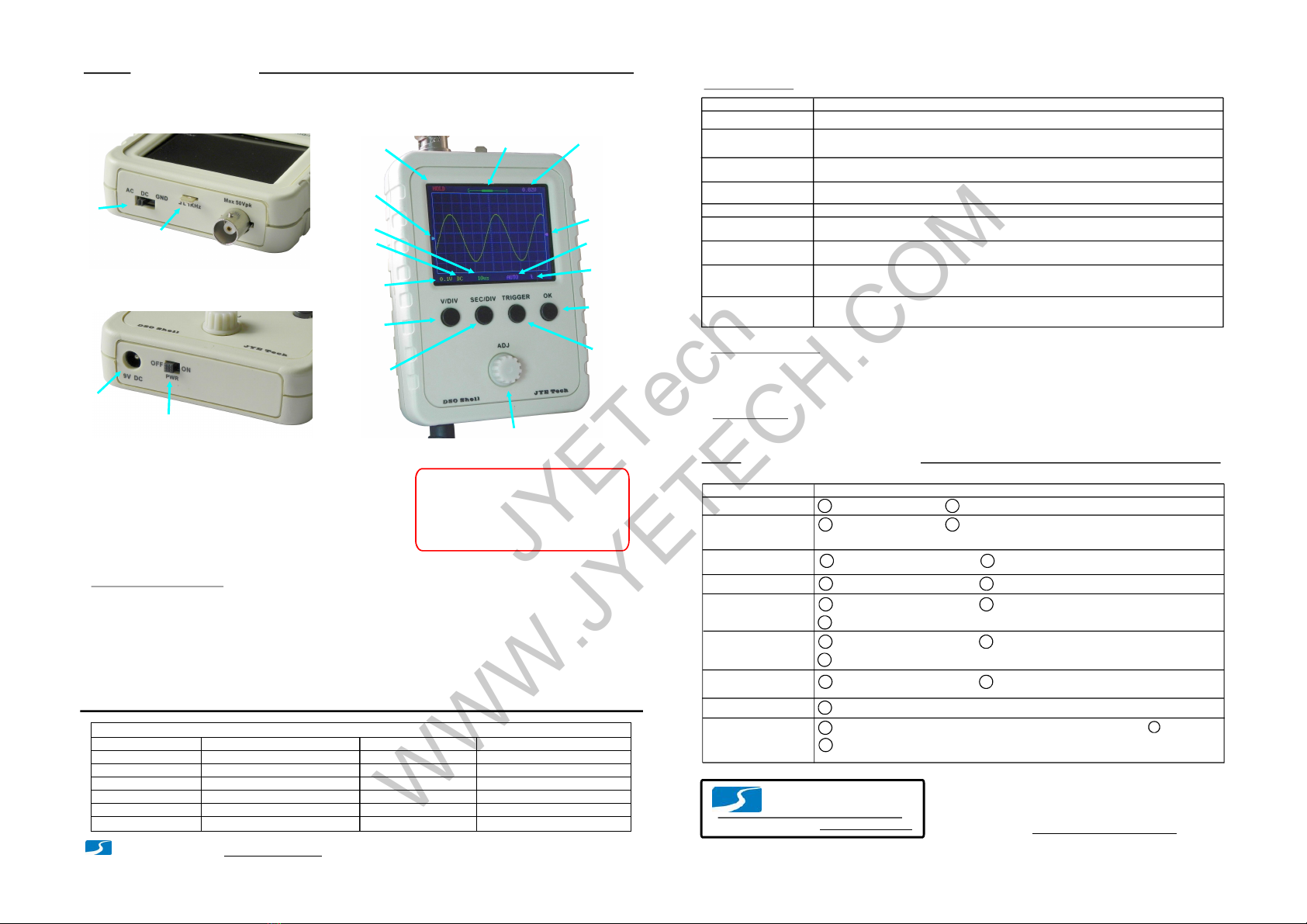
manuals.online logo
Brands
  1. Home
  2. •
  3. Brands
  4. •
  5. JYE Tech
  6. •
  7. Test Equipment
  8. •
  9. JYE Tech DSO Shell 150 User manual

JYE Tech DSO Shell 150 User manual

Page1
- www.jyetech.com -JYETechLtd.
UserManual
Rev.08
DSODIYKit
Shell
Applicablemodels: 15001K,15002K
How toSolderSMDParts
Applysolderto onepad Solderpart tothe pad Solderthe otherpad
Applysolderto acorner
pad SolderIC to thepad. Make
sure pinsarealigned to pads
Solderthe pin at the opposite
cornerso aschip isfixed
Solderallthe rest pinsone
byone
Loc/Ref Qty Descriptions
R19,R20
C9,C12,C13,C14,
C15,C16,C17,C18
R17,R18
C3,C5
U1
U2
U3
78L05,SOT89
1
1
1
1
1
2
2
2
SMDPart Lis
U4
U5
8
ICL7660,SO8
TL084,SO14
74HC4053,SO16
74HC4051,SO16
1K,1%,0805
10K,1%,0805
Captrimmer,30pF
0.1uF,50V,0805
SolderICs
Soldertwo-terminalparts
TL084C
PIN1
IdentifyIC orientation
PlaceICinfront of
yousothat itsmarking
readfromleft toright.
Thefirst pinatlower-
left cornerispin1.
Pin1
3.Donotputironon onepadfor toolong time.Otherwise,
tracesmaypeeloffandgetdamaged.
2. IdentifyICorientationanddiodepolarity(seephotos).
1. Beforesolderingcheckcomponentsagainstthe
partlistto makesureyouhavecorrectparts.
Checkkitcontentsandpartquantities/valuesbythephotoatrightandpartlistinpage2
andpage3.Reportmissingorwrongpartstoyourvendor.
1
Resistor valuesareeasytomis-read.Itisstronglysuggestedtochecktheirvalues
byohm-meterbeforesolderingthemtoboard.
Makesureyouunderstandthepolaritiesandorientationsofallparts.
2
3
Before youstart
Ifyourhavepurchased15002Kkit(SMDnotpre-soldered)youmustinstallall
SMDpartsbeforemountingthethrough-holeparts.Pleaserefertotheinstructions
belowforSMDpartinstallation.Otherwise,proceedtopage2tostartthrough-hole
partassembly.
Important!!!
SMDpartsareonlyinstalledtotheanalogboard(PCBPN#109-15001-xxx).
U6 1 79L05,SOT89
Seepage2for
toolsneeded
Applicablefirmwareversion: 113-15001-110orlater
(ForPCB109-15001-00F)
Photos here arefor
illustrationonly.
Theymaynotmatch
the realboard.
Note:
JYETech
WWW.JYETECH.COM
20-25Wironformostofparts. Forthe
BNCconnectorhigherpoweriron(50-
100W)isrecommendedifavailable.
1
Rosinsolderwire(0.8-1mmdia.)
Digitalmultimeter
Screwdriver(phillips, size#0)
2
3
4
Flushcutter
5
Toolsyouneed
Tweezers
6
Assemblythe MainBoard(followthe orderasnumbered)
Step1
- www.jyetech.com -
JYETechLtd.
1.Checkthemainboard
2.TestSignalTerminal
SW5 DPDT
4.SlideSwitch
:
6.TactSwitches
12x12x7mm
7.RemoveResistorR30
:
SW1, SW2,
SW3, SW4
6.Pin-header(male)
2X 5pin,
2mmpitch
:
J2
SW1 2P3T
3.Slideswitch
:
J1 BNC
5.BNCconnector
:
Page2
The thicker pins need
toheat uplonger toget
good solderingresult.
Note:
DC 9Vpowersupplywith200mA(orhigher)
currentcapacityand5.5x2.1mmplug.
7
1.Resistors
Alwaysmeter resistor
valuesbefore soldering.
Note:
R1510K
R25.1M
:
:
R31.2M
:
R411K:
R5,R6,R14
1K
:
R7300
:
R8,R16150
R991
:
:
R1030:
R11,R12 15:
R15130:
R133K:
AssemblytheAnalogBoard(followthe orderasnumbered)
Step2
2.CeramicCapacitors
0.1F
μ
:
330pF
:
1pF
:
C1
C6150pF
:
C2
C4
4.Electrolyticcapacitors
:
100μ/16VF
Solderpositivepole
(thelongerlead)to
thesquarepad
C8,C10,
C11
J8 4.8x0.8mmterminal
:
Beforesolderingbendtheterminaltothe
shapeasshownintheleftphotoabove.
Note:
Beforemountinganypartstothemainboard
connecta9Vpowersupply(centerpositive)toJ7
ontheboardtocheckthedisplay.
1
2Youshouldseethescopebootsuptoascreen
similartothephotobelow. D1(LED)blinkstwice.
Nowapplypower again.Testpowerswitch
andtactbuttonsfortheircorrectfunctions.
Applypower
Check
display
1
2
5.Pin-header(male)
1X4pin, 0.1"pitch
:
J2
Letironstayononepadoftheresistoruntilsolderon
theotherpadmeltandthenremovethepart.
Note:
R30isusedtobypassSW5soasthemainboardcanbe
testedwithoutthepowerswitch. Itmustberemoved
forcorrectfunctioningofthepowerswitch.
Putleadsthroughmountingholesfromthe side with
partoutline.Ensuecomponent evenlytouchPCB.
1
Solderleadsattheotherside.Soldershouldfully
fillandcoversolderingpads.
Avoidbridgesbetween
neighberingpads.
Cut unusedleads
flushwithcutter.
2
3
SolderingHints
Important
IfyourkitdoesnothaveSMD
devicepre-solderedyouare
stronglysuggestedtoinstall
allSMDpartsbeforemounting
through-holeparts.Pleasesee
instructionsatPage1.
Needle-nosepliers
8
Small slottedscrewdriver(2mmwidth,
forcaptrimmeradjustment)
9
Finished
Donotsolderanypartstothe boardifyoufind
problem. Otherwisewarrantywillbevoided.
Reporttheproblemtovender or JYETech.
J6 0.1"pitch,rightangle
3.PowerConnector(optional)
:
Ifyouhavequestionspostthem
to www.jyetech.com/forum.
Resistors are all 1/8W.
(DCjackis5.5mmdia.
with2.1mmcore)
JYETech
WWW.JYETECH.COM
- www.jyetech.com -
JYETechLtd. Page3
2.AssembleFrontModule
1.SolderRotaryEncoder
Note:
Pleasepayattentiontothe
orientationof PCB.Usethe
sidewithoutlinemarking.
AssemblyFrontModule
Step3
Verifyvoltagesontheanalogboard
CheckVoltages
Step4
FitLCD tofront panelasshown below.1
2Fold the main board overwhile keeping
LCD inplace.
Finalassembly
Putallpartstogether
Step6
3Mount rotaryencoderboard to the
front plate withscrewsand solderthe
board to J2 of themainboard.
Mountwith
screws
(KA2x4)
MakesurePCB evenly
touchthefrontplate
whiledoingC.
A.
B.
C. Solderhere
Calibration
Step5
Screwthe analog board to
backcoverwith the top
bracket attached
1Combine thefrontmoduleand
the backcover
2
Screws
KA2x4 Topbracket
Puttestsignal
terminalthrough
thesmallslot
Make sure receptacle (J4)
mate withpin-header(J2)
3Attach bottom bracket before
holding the two modules
together
4
Bottombracket
Attach the front frame
5Firmlypressthe frame in
6
Frontframe
Screw up at theback
7
Screws
(4positions)
PA2.3x8
Attachknob capand done!
8
Knobcap
Attach the analogboard to the mainboard
bymatingJ2 on theanalog board toJ4 on
themainboard (seephoto).
1
2Apply9VDC powersupplytoJ7 (orJ6)on
themainboard.
3Set coupleswitch to GND position.
Checkvoltagesat the points
asshown in the photo.
4
V4
V2
V1
V3
AV+
V-
AV-
V+
Input
V+
AV+
V-
AV-
V1
V2
V3
V4
+9.30V
+8.35V
5.0V+/-2%
-5.0V+/-2%
-7.86V
0V
0V
0V
~1.65V
References
(*)
(*)
(*)Input dependent
Placenegative
penatDGND
Couple
switch
Applypower
here
Connectthe redcliptothetestsignalterminalandleave the
blackclipun-connected(see photoatbottom).
1
2Applypowerandboot.HolddownADJdialfor3seconds to
bringupTestSignalamplitudedisplayatlower-leftcorner.
PushADJtosetthe amplitude to0.1V.
3Setsensitivityto50mVandadjusttriggerlevelsothat
waveformstable (see HowtoUse”atpage 4). NotenoughA.
GoodB.
ToomuchC.
4TuningC3sothatsharprectangle (photoBatleft)is obtained.
The adjustmentforC3isdone.
5Similarly, forC5calibrationpushADJ tosettestsignalto
3.3V.Change sensitivityto1V.TuningC5sothatsharp
rectangle waveform is obtained.Theadjustmentis done.
AdjusttrimmersC3andC5
Mountto the small PCB
(PN: 109-15002-00A)
(4positions)
Important !
Always removepowerbefore
connectingordisconnecting
theanalog board.
Important!
Tips:
PerformVPosalignment
beforecalibrating C3andC5.
Measurementsapplicable
forPCBversion
109-15001-00Eorlater
Analogboard
part number
C3 C5
Itisstrongly recommended toread thearticle FAQ, Tips, andTroubleshooting”
atunderthesub-forum DSOShell”.www.jyetech.com/forum
(DCjackis5.5mmdia.
with2.1mmcore)
JYETech
WWW.JYETECH.COM
HowtoUse
DisplayandControls
Connections
PowerSupply: Connect9VDCpowersupply to the 5.5x2.1mm
jack atbottom(centerpositive). Power supply
voltage mustbe in the range of8 -10V.
Probe: Connectprobe tothe BNCconnectorattop.
Powersupplyvoltage mustnotexceed
10V.Otherwise itmaydamage theICs
inside.
Attention
1.
Allowedmaximum signalinputvoltage
is 50Vpk(100Vpp)withthe clipprobe.
2.
Operations
[V/DIV]: Selectsensitivity orverticalposition.The selectedparameterindicatorwillbe highlighted.
[SEC/DIV]:
Adjustthe parameterseleted (highlighted). Shortpresstogglesmode.FastAdjustment
[TRIGGER]:
EnterHOLDstate (freeze waveform). Pressitagain willde-freeze.
Coupleswitch: Setcouple to DC,AC, orGND.When GNDisselected the scope inputisisolated frominput
signaland connected to ground (0Vinput).
Analogbandwidth
Sensitivityrange
Resolution
Recordlength
Maxrealtimesamplerate Timebaserange
Maxinputvoltage
Inputimpedance
Powersupply
Currentconsumption
Dimension
Weight
1MSa/s
0--200KHz
5mV/div-20V/div
50Vpk(1Xprobe)
1Mohm/20pF
12bits
1024points
500s/Div-- 10us/Div
9VDC(8 –10V)
~120mA@9V
105x75x22mm
100gram(withoutprobeandPS)
Triggermodes
Triggerposition
Auto,Normal,andSingle
Centerofbuffer
Specifications
SaveWaveform Press[ADJ]& []buttons simultaneously.Thecurrentlydisplayedwaveform
willbe savedtoEEPROM.The existingdata inEEPROMwillbeover-written.
SEC/DIV
www.jyetech.com
JYETechLtd.
Tel.+86-0773-2113856 Techforum: www.jyetech.com/forum
Page4
BasicButtonFunctions
[OK]:
[ADJ]:
Selecttimebase orhorizontalposition.The selectedparameterwillbe highlighted.indicator
Selecttrigger mode, triggerlevel, ortriggeredge.The selectedparameterwillbe highlighted.indicator
MoreFunctions
VPosAlignment
Measurements
ON/OFF
Functions Operations
SetCoupleSwitchtoGNDposition.Holddown[V/DIV]buttonforabout3seconds.
Couple
Switch
TestSignal
output BNC
Connector
Connectors
forPowerSupply
(5.5x2.1mm) Power
Switch
HOLDRUN
Button
/
Oscilloscope
State
Vertical
Position
Indicator
Sensitivity
(V/div)
Couple
Timebase
(s/div)
Trigger
Mode
Trigger
Slope
Trigger
Level
Indicator
TriggerLevel
Readout
Horizontal
Position
Indicator
Sensitivity
Button
Timebase
Button
Trigger
Button
SensitivityButton
Adjustment
Dial
(SignalInput)
DefaultRestore
RecallWaveform
CenterHPos
Center Trigger
Level
Holddown[OK] buttonforabout3seconds.ThiswillturnONorOFFon-screendisplayof
measurementsincludingVmax, Vmin, Vavr, Vpp, Vrms,Freq.,Cycle,Pulsewidth,andDutycycle.
Press[]& []buttons simultaneously.ADJTrigger Recalledwaveformisalwaysdisplayed
inHoldstate.
Holddown[SEC/DIV]and[TRIGGER]buttons simultaneouslyforabout3seconds.
Holddown[SEC/DIV]buttonforabout3seconds.Thiswillmakethedataatthecenter
ofcapturebufferdisplayed.
Holddown[TRIGGER] buttonfor about3seconds.This willsetthetrigger levelt0the
mediumvalueofsignalamplitude.
BadV+
BadV-
Problems PossibleCauses
ConnectorJ7defective.
V1doesnot close
to0V
BadAV+
Troubleshooting
1 2 DiodeD2openor damaged.
1BadC10and/or C11. 2U5(7660)badsolderingordefective.
BadAV- 1
Hint:CheckwithR27disconnectedwouldletyouknowtheissueiscausedbyloadorsource.
2ShortsbetweenAV-andground.
1 2 ShortsbetweenAV+andground.
1SW1isnotsetatGNDposition. 2BadsolderingonR1and/orR2.
3BadsolderingonU1.
V2doesnot close
to0V 1SW1isnotsettoGNDposition. 2BadsolderingonR3and/orR4.
3BadsolderingonU1.
V3doesnot close
to0V 1BadsolderingonU1and/orU2. 2BadsolderingonR5and/orR6.
BadV4 1BadsolderingonR13,R14,andR15.
NoTrace 1IncorrectV4.IfV4iscorrectperformfactorydefaultrestoreasdescribedinbelow.
2Holddown[SEC/DIV]and[TRIGGER] buttonssimultaneouslyfor3seconds.
2
- www.jyetech.com -
JYETechLtd.
(Thisbecomes
triggerstatefor
firmwareversion
-055orlater)
AboutTriggerState
ThetriggercanhavethreestatesincludingHoldoff, Waiting, andTrigged.Theyareexplainedbelow.
Holdoff:
Waiting:
Trigged:
Triggeris disableduntilaportionof samplebufferpriortoatriggerpointisfilledwithrawdata.
Triggeris waitingforavalidsignalslope.
Avalidsignalslopehasbeendetectedandregistered.
RollingMode
Whentimebaseissetto50ms orslower andtriggermodeissettoAUTOthescopewillautomaticallyswitchto
wherewaveformshifts fromrighttoleftconstantly.Thetriggerisdisabledunderthis mode.
RollingMode
FastAdjustment
Shortpress of[ADJ]togglesmodeonandoff for VPos,HPos, and
TriggerLevel.A >>”signappearingattopofscreenindicatesisON.
FastAdjustment
FastAdjustment
SendWaveform
Data
Press[ADJ]& []buttons simultaneouslywillsendwaveform dataintexts via
serialportJ5.The baudrate is 115200. Dataformatis8N1.
V/DIV
U6badsolderingordefective.
U4badsolderingordefective.
JYETech
WWW.JYETECH.COM

This manual suits for next models

5

Other JYE Tech Test Equipment manuals

JYE Tech DSO 068 User manual

JYE Tech

JYE Tech DSO 068 User manual

JYE Tech DSO112A User manual

JYE Tech

JYE Tech DSO112A User manual

JYE Tech DSO112A User manual

JYE Tech

JYE Tech DSO112A User manual

JYE Tech DSO 138 User manual

JYE Tech

JYE Tech DSO 138 User manual

JYE Tech 062 Operating instructions

JYE Tech

JYE Tech 062 Operating instructions

JYE Tech DSO 094 User manual

JYE Tech

JYE Tech DSO 094 User manual

JYE Tech WAVE2 User manual

JYE Tech

JYE Tech WAVE2 User manual

JYE Tech 062 Quick start guide

JYE Tech

JYE Tech 062 Quick start guide

JYE Tech DSO138mini User manual

JYE Tech

JYE Tech DSO138mini User manual

JYE Tech DSO 138 User manual

JYE Tech

JYE Tech DSO 138 User manual

JYE Tech 13803K User manual

JYE Tech

JYE Tech 13803K User manual

JYE Tech DSO 068 User manual

JYE Tech

JYE Tech DSO 068 User manual

JYE Tech DSO 096 Operating manual

JYE Tech

JYE Tech DSO 096 Operating manual

Popular Test Equipment manuals by other brands

Dräger Alcotest 5000 Instructions for use

Dräger

Dräger Alcotest 5000 Instructions for use

TiePie Handyscope TP450 user manual

TiePie

TiePie Handyscope TP450 user manual

Sensidyne Go-Cal user manual

Sensidyne

Sensidyne Go-Cal user manual

Konig CMP-RCT31 manual

Konig

Konig CMP-RCT31 manual

impact Le Chateilier user guide

impact

impact Le Chateilier user guide

SIGLENT TECHNOLOGIES SDS1000 Series user manual

SIGLENT TECHNOLOGIES

SIGLENT TECHNOLOGIES SDS1000 Series user manual

T+M Time TT100 instruction manual

T+M

T+M Time TT100 instruction manual

Silverline 677484 quick guide

Silverline

Silverline 677484 quick guide

Halma Ocean Optics AR-1 Installation and operation instructions

Halma

Halma Ocean Optics AR-1 Installation and operation instructions

Hioki 3454-11 user manual

Hioki

Hioki 3454-11 user manual

Hioki FT4310 instruction manual

Hioki

Hioki FT4310 instruction manual

LeCroy PP006A quick guide

LeCroy

LeCroy PP006A quick guide

az-instrument 8930 Operation manual

az-instrument

az-instrument 8930 Operation manual

AUSTIN POWDER Shock Star user guide

AUSTIN POWDER

AUSTIN POWDER Shock Star user guide

BIRD AT-800 Operation manual

BIRD

BIRD AT-800 Operation manual

Tektronix 3 Series Service manual

Tektronix

Tektronix 3 Series Service manual

2B Technologies Model 408 Operation manual

2B Technologies

2B Technologies Model 408 Operation manual

Humanetics Hybrid III 5th Female user manual

Humanetics

Humanetics Hybrid III 5th Female user manual

manuals.online logo
manuals.online logoBrands
  • About & Mission
  • Contact us
  • Privacy Policy
  • Terms and Conditions

Copyright 2025 Manuals.Online. All Rights Reserved.